Did anybody tried to port (or make to work) the Arduino libraries for following sensors :
1) HDC1080:
Library :
–https://github.com/closedcube/ClosedCub … 80_Arduino
Examples of module:
– https://www.ebay.com/itm/I2C-Temperatur … SwXGtZn3LM
– https://www.ebay.com/itm/HDC1080-High-P … SwAC1aOjXT
2) MS5611:
Library:
– https://github.com/Schm1tz1/arduino-ms5xxx
Examples of module :
– https://www.ebay.com/itm/GY-63-MS5611-h … 2749.l2649
– https://www.ebay.com/itm/GY-63-GY-63-MS … SwZfNaVIMA
Or any other suggested library to work with MapleMini / BluePill via I2C with possibility to select the I2C channel.
Thanks!
Adafruit has a lib since they sell the HDC1080 breakout: https://learn.adafruit.com/adafruit-hdc … g-and-test
Many of Adafruit libs work unchanged with STM32DUINO.
The MS5611 has been reported to work with Teensy. Changes to libs for Teensy is similar to the changes for STM32duino. So, always try and select libraries that are Adafruit/SparkFun authored since these authors write to work across a large selection of sendors.
I have an example of using the BMP180 with STM32F103…
https://www.hackster.io/rayburne/wow-ba … 180-bf70f5
Ray
[mrburnette – Wed Feb 21, 2018 1:49 am] –
Have you tried the existing libraries?
Adafruit has a lib since they sell the HDC1080 breakout: https://learn.adafruit.com/adafruit-hdc … g-and-test
Well, originally I didn’t even thought about using Adafruit library for that since they have HDC1008 sensor, but not HDC1080.
After your comment, I tried and just doesn’t see any sensor on I2C line.
After some search, I found this example directly from TI http://www.ti.com/lit/zip/snac076 .
There was some sort of training: https://training.ti.com/how-interface-h … -using-i2c
With some modifications, I made the HDC1080 sensor to work with MapleMini via following code:
#include <Wire.h>
TwoWire myWire (1);
void setup() {
Serial.begin(15200);
//Initialize I2C Communication
myWire.begin();
//Configure HDC1080
myWire.beginTransmission(0x40);
myWire.write(0x02);
myWire.write(0x90);
myWire.write(0x00);
myWire.endTransmission();
//Delay for Startup of HDC1080
delay(20);
};
void loop()
{
double temperature;
double humidity;
humidity = readSensor(&temperature);
Serial.print("Temperature : ");
Serial.print(temperature);
Serial.print(" \xC2\xB0"); // 0xC2B0 is degree symbol in UTF-8 charset
Serial.println("C");
Serial.print("Humidity : ");
Serial.print(humidity);
Serial.println(" %");
//Wait 1 second for the next reading
delay(1000);
};
double readSensor(double* temperature)
{
//holds 2 bytes of data from I2C Line
uint8_t Byte[4];
//holds the total contents of the temp register
uint16_t temp;
//holds the total contents of the humidity register
uint16_t humidity;
//Point to device 0x40 (Address for HDC1080)
myWire.beginTransmission(0x40);
//Point to register 0x00 (Temperature Register)
myWire.write(0x00);
//Relinquish master control of I2C line
//pointing to the temp register triggers a conversion
myWire.endTransmission();
//delay to allow for sufficient conversion time
delay(20);
//Request four bytes from registers
myWire.requestFrom(0x40, 4);
delay(1);
//If the 4 bytes were returned sucessfully
if (4 <= myWire.available())
{
//take reading
//Byte[0] holds upper byte of temp reading
Byte[0] = myWire.read();
//Byte[1] holds lower byte of temp reading
Byte[1] = myWire.read();
//Byte[3] holds upper byte of humidity reading
Byte[3] = myWire.read();
//Byte[4] holds lower byte of humidity reading
Byte[4] = myWire.read();
//Combine the two bytes to make one 16 bit int
temp = (((unsigned int)Byte[0] <<8 | Byte[1]));
//Temp(C) = reading/(2^16)*165(C) - 40(C)
*temperature = (double)(temp)/(65536)*165-40;
//Combine the two bytes to make one 16 bit int
humidity = (((unsigned int)Byte[3] <<8 | Byte[4]));
//Humidity(%) = reading/(2^16)*100%
return (double)(humidity)/(65536)*100;
}
}
I tried to check if my MS5611 is actually working and observable on I2C bus.
I plugged it based on following map:
MS5611    to    MapleMini

module          I2C_1

Vcc             3.3V

GND             Gnd

SCL             16 with 4.7K pull-up

SDA             15  with 4.7K pull-up

CSB             3.3 or GND to select the address 0x76 or 0x77

SDO             Not Used

PS              High to select the I2C protocol
[Araneus – Wed Feb 21, 2018 11:21 pm] –
…
Any ideas?
I2C was originally done in software, soft I2C. However, the code has been revamped and now is hardware I2C, last Sept.
https://github.com/danieleff/STM32GENER … ire.cpp#L7
Here is the announcement: viewtopic.php?t=2408
Good luck,
Ray
[mrburnette – Thu Feb 22, 2018 12:30 am] –[Araneus – Wed Feb 21, 2018 11:21 pm] –
…
Any ideas?I2C was originally done in software, soft I2C. However, the code has been revamped and now is hardware I2C, last Sept.
https://github.com/danieleff/STM32GENER … ire.cpp#L7Here is the announcement: viewtopic.php?t=2408
Good luck,
Ray
But how to fix that?
Why is it that the current Hardwire will not work with this particular device – mine are not modules but part of an STM32 PCB so I can’t really test them with Arduino, but I am pretty sure this device does work with Arduino and Hardwire i2c…are there any options I can change when initializing Wire that might make it work?
I did modify this library to work with Softwire, but would be nice to figure out why it does not work with the current hardwire ![]()
[bdbell – Thu Feb 22, 2018 6:19 am] –
… if I scan with the Hardwire scanner I see only 2 devices – not the MS5611, but if I scan with the Softwire scanner I see 3 devices, which includes the MS5611.
Well, that certainly seems odd (and not in a good way.)
Maybe an I2C guru is out in the forum and has an answer. This may be one of those non-obvious things that would require a logic analyzer to really track down what is happening.
I will elevate this concern to Roger but understand that his involvement with forum issues is time-constrained at this time.
Done
Ray
[bdbell – Thu Feb 22, 2018 6:19 am] –
I did modify this library to work with Softwire, but would be nice to figure out why it does not work with the current hardwire
Ok. Very dumb question: Can I run on the same pins simultaneously hardware and software I2C?
Or should I use another ones?
P.S. What does OP mean?
[mrburnette – Thu Feb 22, 2018 2:14 pm] –
I will elevate this concern to Roger but understand that his involvement with forum issues is time-constrained at this time.
Thanks!
[Araneus – Thu Feb 22, 2018 5:21 pm] –
…
P.S. What does OP mean?
OP == Original Poster … generally the 1st person to post in a thread
I found an old BP-180 in the parts bin and ran it with both software scanner and hardware scanner (from the examples under “Wire” and both sketches found the sensor without issues.
However, the hardware sketch seems to do “nothing” if “nothing is connected” but the software scanner provides a message about no devices on the bus.
Ray
[mrburnette – Thu Feb 22, 2018 6:00 pm] –[Araneus – Thu Feb 22, 2018 5:21 pm] –
…
P.S. What does OP mean?OP == Original Poster … generally the 1st person to post in a thread
Good to know)
I thought that person is usually called TS – topic starter. Is that region/country related or just a tradition on this forum?
I can’t remember what speed the Hardware I2C is set to by default. I’d hope it was 100Khz but it may have been defaulted to 400KHz which may be too fast for this device
Also, what value pullups are you using.
Vcc 3.3V
GND Gnd
SCL 16 with 4.7K pull-up
SDA 15 with 4.7K pull-up
CSB 3.3 or GND to select the address 0x76 or 0x77
e.g. 2.2k
[RogerClark – Fri Feb 23, 2018 1:50 am] –
I’d try a lower pullup.e.g. 2.2k
I don’t have 2.2, but tried 2.7k and 1.5k – same thing, the device is not available with Hardwire – can only be found using Softwire. The other 2 devices are still found and working.
I tried adjusting the speed in the Hardwire scanner sketch like this;
Wire.begin();
Wire.setClock(100000);
also with no change, 0x77 address of the MS5611 is not found. Is that the correct way to adjust the speed? Are there other options to try to make it work with Hardwire?
[Araneus – Thu Feb 22, 2018 5:21 pm] –
Ok. Very dumb question: Can I run on the same pins simultaneously hardware and software I2C?
Or should I use another ones?
I don’t think that you can use the same pins for Hardwire and Softwire at the same time – which is why I would also like to figure out why this is not working now.
Those $10 8 channel logic analysers is almost essential for doing any thing like this, then you can look at the bus timing in detail
Search for “logic analyzer 24Mhz 8 channel” on your favorite online shopping site
You could potentially try the official STM Arduino core, but I’m not sure if they have fully rolled out support for non STM Nucleo or STM Discovery boards
This also uses Hardware I2C but uses the STM HAL interface
Software is defaulted to use the same pins but can use any pins
You can’t use them both at the same time on the same pins.
[RogerClark – Fri Feb 23, 2018 4:19 am] –
If you don’t already have one.Those $10 8 channel logic analysers is almost essential for doing any thing like this, then you can look at the bus timing in detail
I have one of these, but debugging this on my device which is 25x35mm and has STM32, charge circuit, MPU9250, eeprom, and bluetooth module…is just not going to happen. I will order some breakout pcb’s for MS5611 from taobao to debug with.
Looks a cool analyser.
In similar circumstances I solder some tiny wire to the PCB in order to attach the logic analyser. I normally use “wire wrap” wire but if thats too thick I resort to very thin enameled copper wire
[RogerClark – Thu Feb 22, 2018 9:32 pm] –
Is the issue the I2C Scanner does not work now, or that this device does not work with Hardware I2C ??
The issue is: MS5611 doesn’t work and is not detectable with Hardware I2C.
Even with software I2C I had problems with some devices.
I would write some test code that reads from the ID register on that device ( or the status register etc) and use a logic analyser to look at the bus timing and traffic
PS. I didn’t write the hardware I2C code, so you may get more answers if you look in the GitHub commits history and find out who submitted the code and then PM them
This is not a commercial product, no one gets any money writing or debugging the code.
[Araneus – Fri Feb 23, 2018 6:54 pm] –
The issue is: MS5611 doesn’t work and is not detectable with Hardware I2C.
The issue is: not everyone uses this chip.
If you want to get support for that, you have to provide us the hardware or a signal plot.
[RogerClark – Fri Feb 23, 2018 5:59 am] –
Looks a cool analyser.In similar circumstances I solder some tiny wire to the PCB in order to attach the logic analyser. I normally use “wire wrap” wire but if thats too thick I resort to very thin enameled copper wire
the analyser is pretty old and none of the software available has been updated for a while but it still works ok for the occasional time I need it, I think I will get a new one though too ![]() . I did as you recommended and attached a couple of wires to my existing PCB and took a look at things quickly. I looked at the difference between hardwire i2c accessing the MPU9250, and softwire i2c accessing the MS56211 – because that is what works right now – the built in i2c protocol analyser gave similar results for both, and both plots looked pretty similar so I will have to dig deeper…
. I did as you recommended and attached a couple of wires to my existing PCB and took a look at things quickly. I looked at the difference between hardwire i2c accessing the MPU9250, and softwire i2c accessing the MS56211 – because that is what works right now – the built in i2c protocol analyser gave similar results for both, and both plots looked pretty similar so I will have to dig deeper…
RogerClark wrote:
I would write some test code that reads from the ID register on that device ( or the status register etc) and use a logic analyser to look at the bus timing and traffic
It is about the specific ID (address) of these devices, which is 0x7x.
In my case, too, I could not detect a device with ID 0x78.
After a lot of tries and SW changes I observed that the I2C_SR1_ADD10 bit is set instead of I2C_SR1_ADDR.
It seems that the I2C HW interface switches automatically into 10 bit mode when the first 3 bits of the I2C address byte are 1s, which is the case for 0x7x.
see https://community.st.com/thread/44450-i2c
Because the current HW I2C driver does not handle this I2C_SR1_ADD10 bit at all, the MCU simply hangs in my case.
I am not an expert (yet) in the I2C driver, so if anyone feels confident to implement a workaround, it would appreciate/welcome.
EDIT
It think it would be enough to change line 327 to:
if (sr1 & (I2C_SR1_ADDR|I2C_SR1_ADD10)) {
@bdbell, @mendesgeo, please test this patch and let me us know if it solves the issue for you.
I will pull locall , test and then merge
i2c_scanner_softwire finds the sensor, i2c_scanner_wire not.
Replaced folder “Arduino_STM32-master” with actual version in ~/Arduino/hardware/
Sorry for my stupid question, but what am I missing?
That is the sensor. Fixed 0x76 and two 10k pullups.

Try something like 3.3k or lower
Same situation. “i2c_scanner_softwire finds the sensor, i2c_scanner_wire not.”
Have an old BMP085 with 0x77. Pullup on board with 4.7k. i2c_scanner_softwire finds the sensor, i2c_scanner_wire finds that sensor too …..
(Have loaded, unpacked and copied into ~/Arduino/hardware/ latest version of “Arduino_STM32-master” dated 29.03.2018)

[stevestrong – Sat Mar 31, 2018 1:29 pm] –
So you say 0x77 is found, but 0x76 is not found by i2c_scanner_wire?
I think @kh123 is saying they are both 0x77, but only the BMP085 is detected.
I also tested a BMP085, which is detected at 0x77, but the MS5611 is not detected at the same address with hardwire – only using softwire…
[kh123 – Thu Mar 29, 2018 5:50 pm] –
Have a MS5611 here on my table.i2c_scanner_softwire finds the sensor, i2c_scanner_wire not.
Replaced folder “Arduino_STM32-master” with actual version in ~/Arduino/hardware/
…
That is the sensor. Fixed 0x76…
and
[kh123 – Sat Mar 31, 2018 12:22 pm] –
Have an old BMP085 with 0x77. Pullup on board with 4.7k. i2c_scanner_softwire finds the sensor, i2c_scanner_wire finds that sensor too …..
so one is 0x77 (found), and the other 0x76 (not found). Or am I misinterpreting something?
[stevestrong – Sat Mar 31, 2018 4:28 pm] –[kh123 – Thu Mar 29, 2018 5:50 pm] –
Have a MS5611 here on my table.i2c_scanner_softwire finds the sensor, i2c_scanner_wire not.
Replaced folder “Arduino_STM32-master” with actual version in ~/Arduino/hardware/
…
That is the sensor. Fixed 0x76…and
[kh123 – Sat Mar 31, 2018 12:22 pm] –
Have an old BMP085 with 0x77. Pullup on board with 4.7k. i2c_scanner_softwire finds the sensor, i2c_scanner_wire finds that sensor too …..so one is 0x77 (found), and the other 0x76 (not found). Or am I misinterpreting something?
not sure about @kh123 – but in my case the MS5611 and BMP085 are both set to 0x77 address, only the BMP085 gets detected by hardwire, both detected with softwire
I thought that is hardcoded in the chip, unless some additional pins extend that.
EDIT
OK, I found this info:
The MS5611-01BA address is 111011Cx, where C is the complementary value of the pin CSB
So if you set CSB to “0” then the address is 0x77.
However, in this case I really don’t understand why one device is found and the other not, although both have the same address …
[stevestrong – Sat Mar 31, 2018 4:44 pm] –
How is it possible that you can set the MS5611 address?
I thought that is hardcoded in the chip, unless some additional pins extend that.EDIT
OK, I found this info:
The MS5611-01BA address is 111011Cx, where C is the complementary value of the pin CSB
So if you set CSB to “0” then the address is 0x77.However, in this case I really don’t understand why one device is found and the other not, although both have the same address …
Yes, my ‘usual’ test devices have CSB set to 0 so address is 0x77 – I cannot change this in my test devices, but I will try to do a test tomorrow with MS5611 @ 0x76 to see if it’s detected
My MS5611 has a fixed address 0x76 on that shield and the BMP085 with fixed 0x77.
I did a capture with both BMP085 and MS5611 in HW and SW mode using my logic sniffer – but not sure what to look for here. Here is software mode where they are both being detected at 0x77
I am searching and seeing what I can figure out, but If someone could suggest what to look for, or a site that explains how to debug this I would appreciate it.
It would be good to post pictures having signals with higher resolution, only the part where the devices are accessed, only SDA and SCL, no more signals.
[stevestrong – Sun Apr 01, 2018 1:20 pm] –
Your plots do not have good resolution, I cannot detect any start or stop condition, not to mention the address…
It would be good to post pictures having signals with higher resolution, only the part where the devices are accessed, only SDA and SCL, no more signals.
I am using an old Open Bench Logic Sniffer with the OLS client – the version I was using did not allow turning off other signals, but I just found a newer version that does. I can export the plots as csv, png, or vcd format – what is best for you? The plots I attached before are of the complete transaction – you need just the start of the transaction – like this?
But the main problem remains the resolution, I cannot see all the SCL pulses toggling.
Can’t you increase the signal sampling rate?
If the SCL is 100 kHz, then the sampling rate should be at least the double of it, better 4x or 10x (1MHz sampling rate would be ideal).
[stevestrong – Sun Apr 01, 2018 4:12 pm] –
If the SCL is 100 kHz, then the sampling rate should be at least the double of it, better 4x or 10x (1MHz sampling rate would be ideal).
ah, ok – now the data is starting to make a lot more sense ![]()
I have changed the sampling rate to 1MHz, also the data from the internal i2c protocol analyzer is making a lot more sense now too – thanks!
[stevestrong – Sun Apr 01, 2018 6:29 pm] –
Now start the i2c scanner from 0x76, we only need this address and the next one.
OK, so I have done a lot more testing on this – I created a sketch that allowed me to set a specific address to scan, and be able to change whether the sketch was using SW or HW. When I started testing it something strange I found was that I was able to get HW to detect if I upload it after I test in SW mode ![]()
I though perhaps something was wrong in my coding, so I created 2 separate sketches – one for SW and one for HW (attached). If I run the standard i2c HW scanner it does not find the device, then I upload my single address HW scanner – still not found. But – if I test the Softwire scanner (or my single address SW sketch) – it is found, and then I upload my HW sketch and it is found.
Perhaps a little confusing – but basically if I run the attached HW sketch after running the standard Softwire sketch the device is found. I am also attaching plots showing the HW detecting and not detecting, and the SW detecting. I don’t quite understand what is happening here… ![]() Also I noticed that in order to get the scanner to find address 0x77 I had to set byte address = 119;
Also I noticed that in order to get the scanner to find address 0x77 I had to set byte address = 119; ![]()
But I ordered now this module, I will make some more test when it arrives.


My module is travelling arround the world…
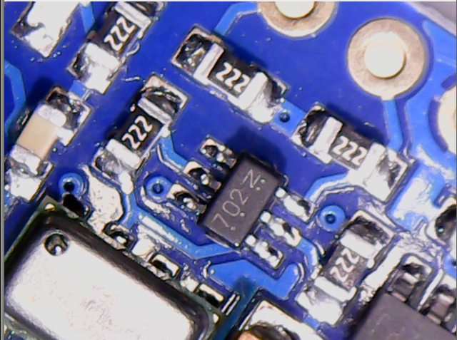
Here is a pic showing the resistors around the double MOS-FET on that board.
@stevestrong.
Have a dozen or so small packages on the way from China, at the moment. Seems, the container ships at the moment are all running “dead slow speed” ![]()
My test results: the I2C interface works fine.
The chip gives ACK only when:
– first time after POR (pushing the reset button not enough, it must get a power cycle off and on again)
AND
– the CSB and PS pins are connected to Vcc
AND
– its address (0x76) is the first scanned one.
So I think the problem has two faces.
1. The chip is very sensitive. According to its datasheet:
RESET SEQUENCE
The reset can be sent at any time. In the event that there is not a successful power on reset this may be caused by
the SDA being blocked by the module in the acknowledge state. The only way to get the MS5611-01BA to function
is to send several SCLKs followed by a reset sequence or to repeat power on reset.
So if the I2C scanner uses a different address than its own, the chip may go crazy. It does no have an MCU incorporated.
Since the IC does not have a microcontroller inside, the commands for I2C and SPI are quite similar.
2. This is amplified by the board schematic using on-board 3.3V regulator and level shifters.
In addition, even if the board has 2k2 pull-up resistors on CSB and PS pins to Vcc (3.3V or 5V), you have to shorten these pins to Vcc in order to work.
Why these conditions influences the behavior only in case of hardware I2C?
I am not sure, but I know that there is similar problem for SD card modules with level shifters, they do not work with the hardware SPI interface.
Next test would be to exclude (over-bridge) the on-board regulator and the level shifters.
Meanwhile, could anyone test the chip behavior under these conditions I mentioned and confirm?
Just to be sure that it is not only my board somehow special.
It is not a hardware issue, it works with or without the level shifters and/or 3.3V regulator.
The MS5611 does not like the bus reset procedure which is done in the hardware I2C library if the chip replies with NACK.
I disabled that line and – voila – it started to work correctly.
I am not sure why we need that, because the software I2C lib does not perform any reset in case of NACK.
So we maybe can disable that lines in order to avoid any further issue like: “Why software I2c works and HW I2C doesn’t?”
[stevestrong – Tue Apr 24, 2018 9:51 am] –
In that case you should be able to test it by removing those two lines as indicated above.
If I comment out those two lines the Hardwire scanner does not find anything, if I leave them in the it finds the MPU9150, but not MS5611. Softwire finds both whether the lines are commented or not…I am using 1.8.5 IDE and I downloaded Rogers latest core to make sure I had not changed anything else…
Actually only line 53 should be replaced by:
i2c_master_enable(sel_hard, dev_flags); // avoid I2C_BUS_RESET
[stevestrong – Wed Apr 25, 2018 7:37 am] –
Actually only line 53 should be replaced by:
i2c_master_enable(sel_hard, dev_flags); // avoid I2C_BUS_RESET
