At the beginning just some quick facts and status updates:
Concept:
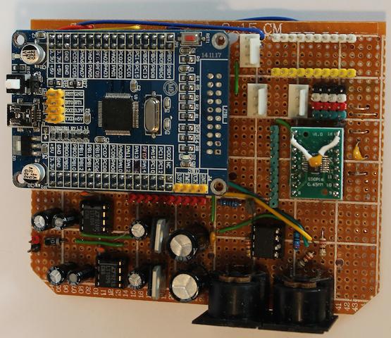
A STM32F103 based 4-channel (polyphonic) Wavetable-Synthesizer with individual outputs for an analog filter board.
Voice out via 2pcs PT8211 (cheap) audio DAC’s [main code working – no I2S possible yet, but thanks to Vassilis with SPI code, todo: implementing DMA]
USB-MIDI and Hardware MIDI [have set up a separate branch using USB-MIDI instead of USB-Serial – Test code working]
Display (ILI9341 with touch + secondary OLED), Encoders, Knobs…. [todo, but no priority for the user interface first]
Direct import of Waldorf Blofeld multi-wavetables via MIDI (USB) [working, code written]
SPI-flash (Winbond) EEPROM (2-4MB) for storing maybe an additional I2C EEPROM (more write/erase cycles)
several LTC1665 octal-8-Bit-DAC's for controlling the filter board and voice volume [code examples written, maybe I use direct PWM instead of this DAC's]
STM32F103 is individual, but I need 64k RAM (for wavetables), so maybe RET6
3d-model:
[img]http://666kb.com/i/d1qbw6ccyw991xrfv.jpg[/img]
[i][b]to be continued[/b][/i]
At the beginning just some quick facts and status updates:
Concept:
A STM32F103 based 4-channel (polyphonic) Wavetable-Synthesizer with individual outputs for an analog filter board.
Voice out via 2pcs PT8211 (cheap) audio DAC’s [main code working – no I2S possible yet, but thanks to Vassilis with SPI code, todo: implementing DMA]
USB-MIDI and Hardware MIDI [have set up a separate branch using USB-MIDI instead of USB-Serial – Test code working]
Display (ILI9341 with touch + secondary OLED), Encoders, Knobs…. [todo, but no priority for the user interface first]
Direct import of Waldorf Blofeld multi-wavetables via MIDI (USB) [working, code written]
SPI (Winbond) EEPROM (2-4MB) for storing maybe an additional I2C DAC (more write/erase cycles)
several LTC1665 octal-8-Bit-DAC's for controlling the filter board and voice volume [code examples written, maybe I use direct PWM instead of this DAC's]
STM32F103 is individual, but I need 64k RAM (for wavetables), so maybe RET6
3d-model:
[img]http://666kb.com/i/d1qbw6ccyw991xrfv.jpg[/img]
[i][b]to be continued[/b][/i][/quote]
May I suggest you use SPI Flash instead of EEPROM? perhaps you meant that, but if not, flash should be faster than eeprom. Regarding the MCU, the RCT6 boards I have all have 512 of flash and 64 of RAM, so at least for development you can use that.
Both the RCT and RET have 2 integrated DACs, so you can use those for control, or extra channel or whatever you wish.
yes, I mean’t SPI Flash (like winbond W25Q64FV). The real problem are the write/read cycles, taken from the datasheets:
W25Q64FV – 8MB flash spi chip (100.000 write cycles)
24lc512 – 64kB flash i2c chip (1.000.000 write cycles)
So for “storing data permanent on the fly” (data’s like patch files, common files, no audio files) the 23lc512 should be the better option. But maybe I’m over-cautious. The audio is directly played from internal RAM so I won’t need real high speed for the external storage.
For development I’ll use my big VET board (winbond and I2C flash onboard) for the final product I’m not sure yet.
The DAC’s might be useful (if there is no pin conflict with SPI, I need all 3 SPI ports) but only two pcs are problematic, because I need following same(!) DAC’s (or filtered PWM’s):
4x voltage controlled volume (VCA)
4x voltage controlled cutoff frequency (VCF)
1-4x voltage controlled Resonance (—> maybe this for DAC, I do not need to set resonance for each voice independent)
so one octal DAC + 1channel onboard DAC.
I know them I have at least two of them from a microchip sample delivery at home. (I own many SPI/I2c flash/eeprom/RAM chips, so I’m going to experiment the best out)
And the RC and higher have the FSMC
I was thinking about FSMC and adding some 1-2MB SRAM’s (NORs) but actual I don’t need them (64kb is more than enough for me and for the wavetables) Maybe this could be a future update: “real” samples instead of wavetables.
About DACs, perhaps there are some octal or at least quad DAC chips available that work with SPI, in SPI mode not I2S
I own some LT1665 8-bit octal DAC’s -> they are SPI, but to be concret:
I need 4 channels 16-bit DAC’s for audio out so 2pcs PT8211 are perfect for this condition —> 48khz frequency. The wavetables are real time creatied with this frequency I know getting I2s working would be a great benefit.
The rest of the DAC’s are for control lines they don’t need a high frequency (about 40-100hz update and only if the value has changed) and no higher bit rate (8-bit is more than good, because I use expo converters in my audio filter circuit, MIDI “understand” only 7-bit values for normal CC signals (and one line with 14bit -> pitch bend), so 8-bit is enough)) I also implemented in my filter design a pwm-filter, so I’ll try pure PWM (with a higher rate) also, but I would need at least 9 PWM pins.
So my next steps until I get the PCB boards:
optimizing the audio out code with the PT8211 DAC’s (even with DMA SPI or I2S (but to be honest: I don’t see getting I2s working with my skills)
If so, you can use 1 or several timers, with the right values for reload, prescaler and OCR, and set them to free running, then change the values on the fly as needed to change their frequency and period.
I believe you will have 7 timers available in RCT or higher MCUs, each with 4 output compare outputs.
Image a sine table with 256 entries. (Values -127 to 127). You step through this table with a variable frequency (say 30hz). So you have setup a timer with the frequency 7680hz (256*30hz). This would be a pretty bad, but functional LFO. (To change the frequency you have to change the timer)
The use of this LFO is modular, some examples:
You can modulate the pitch of the main oscillator: the frequency of the main oscillator is 440HZ (concert pitch “A”) you add the LFO, so the oscillator sweeps between 313hz and 567hz with a sine modulation and a speed of 30hz.
There are many targets you can modulate: The volume, the cutoff frequency, the balance between oscillator1 and osc2, even the intensity of LFO2 or the speed of LFO3.
So in my synth the LFO would only “be in software” changing the pitch of an osc, but would give out a separate DAC value if I’m modulating the Cutoff Filter (external analog hardware)
In the past, I did it with one timer for all LFO’s:
(example code out of my brain)
this function is on a timer set up to the wished maximum frequency * 256
byte div_delay[MAX_VOICES*3];

byte lfo_table_counter[MAX_VOICES*3];

byte lfo_freq[MAX_VOICES*3];

int8_t lfo_value[MAX_VOICES*3];

// lfo_table[] different tables with 256 entries (like sine, sqr, saw up....)

lfo_freq[0]=20;

lfo_freq[1]=100; // and so on...

void LFO()

{

for (byte currentvoice=0;currentvoice<=MAX_VOICES*3;currentvoice++) //  need 3 LFO's for each voice

{

div_delay[currentvoice]++;

if (div_delay[currentvoice]>=freq[currentvoice])

lfo_table_counter[currentvoice]++;

lfo_value[currentvoice]=lfo_table[currentvoice];

}

}code in short, truncated:
before setup:
SemaphoreHandle_t event_signal;EDIT:
Try setting the wait time for the semaphore as portMAX_DELAY rather than NULL
Also, why do you take the semaphore after creating it?
Is that so the DMA routine first sends a batch of 0? otherwise, you dont need to take it, let the buffer filling task take it.
I’ve the complete audio-engine again in the DMA unless I can clear the problems. I’ve 2-3 RTOS tasks running: some TFT gadgets, a note player and a LFO.
This a hard begin learning RTOS, because I use real time critical stuff.
I added a “before” version of my sketch (audio engine on RTOS) only two tasks: melody (only a stripped freq sweep enabled) and audio_engine. (TFT is only start screen) As you can see in the DMA IRQ there are many uncommented codes I tried out.
I think the best would be a “RTOS one trigger function” for audio_engine –> the trigger would be in the DMA IRQ, because it’s a little bit of waste of resources having the audio_engine loop “always on”
The second sketch file (I2s-PT8211-synth-buffer_TFT_RTOS2) is my current working sketch (apart from the buffer problem it works pretty good)
edit:
Also, why do you take the semaphore after creating it?
this was only for testing (I saw that in an example)
http://www.freertos.org/taskresumefromisr.html
The DMA IRQ set the audio_engine task on resume, the task triggers and terminate itself.
Another theory: The update time for task is 1khz, but I use about 48khz in the dma irq (setting up a higher rate in the rtos-config doesn’t bring cure)
http://www.freertos.org/taskresumefromisr.html
The DMA IRQ set the audio_engine task on resume, the task triggers and terminate itself.
Another theory: The update time for task is 1khz, but I use about 48khz in the dma irq (setting up a higher rate in the rtos-config doesn’t bring cure)
Yeah, this mixes a slightly white noise to to audio output, sounds really good, but not the thing I want
Ok, I got it nearly running (but with worse audio quality than doing everything in DMA ISR), cause I set the audio_engine to a LOWER task. See added sketch
ok, there is the possibility to set temporary a task to a higher priority, but the syntax i a little bit confusing to me:
I tried
void DMAEvent() {

BaseType_t xHigherPriorityTaskWoken = pdTRUE;

xSemaphoreGiveFromISR(event_signal, &xHigherPriorityTaskWoken ); // trigger
portYIELD_FROM_ISR( xHigherPriorityTaskWoken );
dma_clear_isr_bits(DMA2, DMA_CH2);
}
static void vFillBufferTask(void *pvParameters) {

while (1) {
if (xSemaphoreTake(event_signal, 0))

{
/* Pins:

#define BOARD_SPI3_NSS_PIN      PA15 x timer

#define BOARD_SPI3_SCK_PIN      PB3 x timer

#define BOARD_SPI3_MISO_PIN     PB4 x timer

#define BOARD_SPI3_MOSI_PIN     PB5 x timer
MCK Pins:

I2S2MCK: PC6  Timer 8, Channel 1

I2S3MCK: PC7  Timer 8, Channel 2
#define BOARD_SPI1_NSS_PIN      PA4

#define BOARD_SPI1_SCK_PIN      PA5

#define BOARD_SPI1_MISO_PIN     PA6

#define BOARD_SPI1_MOSI_PIN     PA7

*/
#include <MapleFreeRTOS821.h>

#include "libmaple/spi.h"

#include "libmaple/dma.h"

#include "header.h"

#include <SPI.h>
#include <ILI_SdSpi.h>

#include <ILI_SdFatConfig.h>

#include <ILI9341_due_gText.h>

#include <ILI9341_due.h>

#include "fonts/Arial14.h"

#define TFT_DC PA1

#define TFT_CS PA0

#define rst  PA2

#define	BLACK           0x0000

#define	RED             0xF800

#define	GREEN           0x07E0

//#define	BLUE            0x001F

#define	BLUE            0x102E

#define CYAN            0x07FF

#define MAGENTA         0xF81F

#define YELLOW          0xFFE0

#define ORANGE          0xFD20

#define GREENYELLOW     0xAFE5

#define DARKGREEN       0x03E0

#define WHITE           0xFFFF

// Use hardware SPI (on Uno, #13, #12, #11) and the above for CS/DC

ILI9341_due tft = ILI9341_due(TFT_CS, TFT_DC, rst);
ILI9341_due_gText t1(&tft);

#define LED PD2

#define buffer_size 2

#define buffer_size 128

int16_t i2s_buffer[buffer_size];

int16_t * i2s_buffer_tophalf = &i2s_buffer[buffer_size/2];

int16_t * i2s_buffer_ptr;

QueueHandle_t dmaQueue;
SemaphoreHandle_t event_signal;

xTaskHandle TaskHandle_1;

byte melo[] = {

40, 52, 40, 52,  47, 59, 47, 59,

40, 52, 40, 52,  47, 59, 47, 59,

43, 55, 43, 55,  50, 62, 50, 62,

43, 55, 43, 55,  50, 69, 50, 69,

};

byte wavecounter2 = 0;

byte counter = 0;

byte notestep = 0;

byte dacval = 0;

byte dacval2 = 0;

volatile byte testvol = 127;

volatile byte testvol2 = 127;

byte freq = 30;

void setup() {
disableDebugPorts(); // need to use SPI3!!!!

Serial.begin(9600);

tft.begin();

tft.setRotation(iliRotation270);

tft.fillScreen(BLUE);

t1.defineArea(0, 0, 320, 240);

t1.selectFont(Arial14);

timer_set_mode(TIMER6, 2, TIMER_DISABLED); // disable pwm on pins fuer jeden setzen!

gpio_set_mode(GPIOA, 15 , GPIO_AF_OUTPUT_PP); // SS pin

gpio_set_mode(GPIOB, 3 , GPIO_AF_OUTPUT_PP); // sck

gpio_set_mode(GPIOB, 4 , GPIO_INPUT_FLOATING); // miso

gpio_set_mode(GPIOB, 5 , GPIO_AF_OUTPUT_PP); // mosi

gpio_set_mode(GPIOC, 7 , GPIO_AF_OUTPUT_PP); // bck
createNoteTable(SAMPLE_RATE);

createWavetables();

ulPhaseIncrement_A[0] = nMidiPhaseIncrement[69]; // 69=440hz reference

ulPhaseIncrement_A[1] = nMidiPhaseIncrement[69]; // 69=440hz reference

pinMode (LED, OUTPUT);
tft.fillRect(0, 0, 320, 15, RED);

t1.setFontColor(WHITE, RED);

t1.drawString("* ILI9341_due UTFT 240x320 Demo *", 47, 0);

tft.fillRect(0, 226, 320, 240, tft.color565(64, 64, 64));

t1.setFontColor(YELLOW, tft.color565(64, 64, 64));

t1.drawString("bis dahin komm ich", gTextAlignBottomCenter, 227);

i2s_begin(SPI3); // untere Funktion verwenden

// ****DMA ******

dma_init(DMA2);

spi_tx_dma_enable(SPI3);

dma_attach_interrupt(DMA2, DMA_CH2, DMAEvent);

spi_tx_dma_enable(SPI3);

dma_setup_transfer(DMA2, DMA_CH2, &SPI3->regs->DR, DMA_SIZE_16BITS,  i2s_buffer, DMA_SIZE_16BITS, (DMA_MINC_MODE  | DMA_CIRC_MODE | DMA_FROM_MEM | DMA_HALF_TRNS | DMA_TRNS_CMPLT));

dma_set_num_transfers(DMA2, DMA_CH2, buffer_size);

dma_set_priority(DMA2, DMA_CH2, DMA_PRIORITY_VERY_HIGH);

dma_enable(DMA2, DMA_CH2);// enable transmit

testvol = 127;
dmaQueue = xQueueCreate ( 2, sizeof (int16_t) );
vSemaphoreCreateBinary( event_signal ); // Create the semaphore

xSemaphoreTake(event_signal, 0);        // Take semaphore after creating it.

xTaskCreate(vFillBufferTask,

"Task1",

configMINIMAL_STACK_SIZE,

NULL,

tskIDLE_PRIORITY + 2,

&TaskHandle_1);

xTaskCreate(vMusicTask,

"Task2",

configMINIMAL_STACK_SIZE,

NULL,

tskIDLE_PRIORITY + 1,

NULL);

vTaskStartScheduler();
}
void loop() {
}
static void vMusicTask(void *pvParameters) {

while (1)

{

freq++;

if (freq == 90)

freq = 30;

testvol = 127;

ulPhaseIncrement_A[0] = nMidiPhaseIncrement[byte(freq)]; // should be 440hz

ulPhaseIncrement_B[0] = nMidiPhaseIncrement[byte(freq)];

ulPhaseIncrement_A[1] = nMidiPhaseIncrement[byte(90-freq)]; // should be 440hz

ulPhaseIncrement_B[1] = nMidiPhaseIncrement[byte(90-freq)];

vTaskDelay(100);

/*

byte tune =  melo[notestep];
ulPhaseIncrement_A[0] = nMidiPhaseIncrement[byte(tune)];

ulPhaseIncrement_B[0] = nMidiPhaseIncrement[byte(tune) + 7];

ulPhaseIncrement_A[1] = nMidiPhaseIncrement[byte(tune + 12)];

ulPhaseIncrement_B[1] = nMidiPhaseIncrement[byte(tune) + 19];

//   Serial.println(nMidiPhaseIncrement[byte(tune)] );

notestep += 1;

if (notestep > 31)

notestep = 0;

//   tft.fillRect(tune * 3, 100, 20, 20, GREEN);

for (byte x = 0; x < 127; x++)

{

testvol = x;

vTaskDelay(300);
}

for (byte x = 0; x < 127; x++)

{

testvol = 127 - x;
vTaskDelay(900);

}

//   tft.fillRect(tune * 3, 100, 20, 20, BLUE);

*/

}

}
void DMAEvent() {

static signed BaseType_t xYieldRequired;

//  xSemaphoreGiveFromISR(event_signal, NULL); // trigger

if ((dma_get_isr_bits( DMA2, DMA_CH2) & 0x2)==1) {

xQueueSendFromISR(dmaQueue, i2s_buffer, &xYieldRequired);

}

else {

xQueueSendFromISR(dmaQueue, i2s_buffer_tophalf, &xYieldRequired);

}

dma_clear_isr_bits(DMA2, DMA_CH2);
portEND_SWITCHING_ISR(xYieldRequired);

}
static void vFillBufferTask(void *pvParameters) {

while (1) {
if (xQueueReceive (dmaQueue, i2s_buffer_ptr , portMAX_DELAY)

{

//  xSemaphoreTake(event_signal, 0);

//  portENTER_CRITICAL();

//  gpio_write_bit(GPIOD, 2, 1); // test led on

// byte flip=0;

for (int cc = 0; cc < (buffer_size/2)-1 ; cc +2)

{

//   flip=!flip;

//  if (flip==0)

// {

ulPhaseAccumulator_A[0] += ulPhaseIncrement_A[0] % SAMPLES_PER_CYCLE_FIXEDPOINT;

//        if (ulPhaseAccumulator_A[0]  > SAMPLES_PER_CYCLE_FIXEDPOINT)

//        {

//          ulPhaseAccumulator_A[0]  -= SAMPLES_PER_CYCLE_FIXEDPOINT;

//        }

ulPhaseAccumulator_B[0] += ulPhaseIncrement_B[0] % SAMPLES_PER_CYCLE_FIXEDPOINT;

//        if (ulPhaseAccumulator_B[0]  > SAMPLES_PER_CYCLE_FIXEDPOINT)

//        {

//          ulPhaseAccumulator_B[0]  -= SAMPLES_PER_CYCLE_FIXEDPOINT;

//        }

waveout_A[0] = (wavetable_A[ulPhaseAccumulator_A[0] >> 20] + wavetable_B[ulPhaseAccumulator_B[0] >> 20]) / 2;
//   waveout_A[0] = ( (waveout_A[0] * testvol) / 128);

i2s_buffer_ptr[cc]  = waveout_A[0];

// }

//    else

//    {

ulPhaseAccumulator_A[1] += ulPhaseIncrement_A[1] % SAMPLES_PER_CYCLE_FIXEDPOINT;

//        if (ulPhaseAccumulator_A[1]  > SAMPLES_PER_CYCLE_FIXEDPOINT)

//        {

//          ulPhaseAccumulator_A[1]  -= SAMPLES_PER_CYCLE_FIXEDPOINT;

//        }

ulPhaseAccumulator_B[1] += ulPhaseIncrement_B[1] % SAMPLES_PER_CYCLE_FIXEDPOINT;

//        if (ulPhaseAccumulator_B[1]  > SAMPLES_PER_CYCLE_FIXEDPOINT)

//        {

//          ulPhaseAccumulator_B[1]  -= SAMPLES_PER_CYCLE_FIXEDPOINT;

//        }

waveout_A[1] = (wavetable_A[ulPhaseAccumulator_A[1] >> 20] + wavetable_B[ulPhaseAccumulator_B[1] >> 20]) / 2;

waveout_A[1] = ( (waveout_A[1] * testvol2) / 128);

i2s_buffer_ptr[cc+1] = waveout_A[1] ;

//    }
}
//  gpio_write_bit(GPIOD, 2, 0);  // test led off

//xSemaphoreTake(event_signal, 0);

// portEXIT_CRITICAL();

//vTaskSuspend(&TaskHandle_1   );

}

// vTaskPrioritySet( &TaskHandle_1 , tskIDLE_PRIORITY + 0 );
}

}
Sadly, it wont function, because no data is send via MOSI (logic anal. –> SCK ok, WS ok, MOSI —> no data)
I’d to change some things caused by compiling errors (cleaned up code at the bottom):
At first the line
static signed BaseType_t xYieldRequired;
dma_setup_transfer(DMA2, DMA_CH2, &SPI3->regs->DR, DMA_SIZE_16BITS, i2s_buffer , DMA_SIZE_16BITS, (DMA_MINC_MODE | DMA_CIRC_MODE | DMA_FROM_MEM | DMA_HALF_TRNS | DMA_TRNS_CMPLT));Result is the same as in many things I tried out to outsource the buffer code from the DMA IRQ into a RTOS task: crackling sound. If I set
(xQueueReceive (dmaQueue, i2s_buffer , portMAX_DELAY))
the other (low priority) tasks run, but crackling sound
if I set
(xQueueReceive (dmaQueue, i2s_buffer , 0))
no low priority task would fire up.
A working copy: (with crackling sound)
/* Pins:

#define BOARD_SPI3_NSS_PIN      PA15 x timer

#define BOARD_SPI3_SCK_PIN      PB3 x timer

#define BOARD_SPI3_MISO_PIN     PB4 x timer

#define BOARD_SPI3_MOSI_PIN     PB5 x timer
MCK Pins:
I2S2MCK: PC6 Timer 8, Channel 1
I2S3MCK: PC7 Timer 8, Channel 2
#define BOARD_SPI1_NSS_PIN PA4
#define BOARD_SPI1_SCK_PIN PA5
#define BOARD_SPI1_MISO_PIN PA6
#define BOARD_SPI1_MOSI_PIN PA7
*/
#include <MapleFreeRTOS821.h>
#include "libmaple/spi.h"
#include "libmaple/dma.h"
#include "header.h"
#include <SPI.h>
#include <ILI_SdSpi.h>
#include <ILI_SdFatConfig.h>
#include <ILI9341_due_gText.h>
#include <ILI9341_due.h>
#include "fonts/Arial14.h"
#define TFT_DC PA1
#define TFT_CS PA0
#define rst PA2
#define BLACK 0x0000
#define RED 0xF800
#define GREEN 0x07E0
//#define BLUE 0x001F
#define BLUE 0x102E
#define CYAN 0x07FF
#define MAGENTA 0xF81F
#define YELLOW 0xFFE0
#define ORANGE 0xFD20
#define GREENYELLOW 0xAFE5
#define DARKGREEN 0x03E0
#define WHITE 0xFFFF
// Use hardware SPI (on Uno, #13, #12, #11) and the above for CS/DC
ILI9341_due tft = ILI9341_due(TFT_CS, TFT_DC, rst);
ILI9341_due_gText t1(&tft);
#define LED PD2
//#define buffer_size 256
#define buffer_size 64
int16_t i2s_buffer[buffer_size];
int16_t * i2s_buffer_tophalf = &i2s_buffer[buffer_size / 2];
int16_t * i2s_buffer_ptr;
QueueHandle_t dmaQueue;
SemaphoreHandle_t event_signal;
xTaskHandle TaskHandle_1;
byte melo[] = {
40, 52, 40, 52, 47, 59, 47, 59,
40, 52, 40, 52, 47, 59, 47, 59,
43, 55, 43, 55, 50, 62, 50, 62,
43, 55, 43, 55, 50, 69, 50, 69,
};
byte wavecounter2 = 0;
byte counter = 0;
byte notestep = 0;
byte dacval = 0;
byte dacval2 = 0;
volatile byte testvol = 127;
volatile byte testvol2 = 127;
byte freq = 30;
void setup() {
disableDebugPorts(); // need to use SPI3!!!!
Serial.begin(9600);
tft.begin();
tft.setRotation(iliRotation270);
tft.fillScreen(BLUE);
t1.defineArea(0, 0, 320, 240);
t1.selectFont(Arial14);
timer_set_mode(TIMER6, 2, TIMER_DISABLED); // disable pwm on pins fuer jeden setzen!
gpio_set_mode(GPIOA, 15 , GPIO_AF_OUTPUT_PP); // SS pin
gpio_set_mode(GPIOB, 3 , GPIO_AF_OUTPUT_PP); // sck
gpio_set_mode(GPIOB, 4 , GPIO_INPUT_FLOATING); // miso
gpio_set_mode(GPIOB, 5 , GPIO_AF_OUTPUT_PP); // mosi
gpio_set_mode(GPIOC, 7 , GPIO_AF_OUTPUT_PP); // bck
createNoteTable(SAMPLE_RATE);
createWavetables();
ulPhaseIncrement_A[0] = nMidiPhaseIncrement[69]; // 69=440hz reference
ulPhaseIncrement_A[1] = nMidiPhaseIncrement[69]; // 69=440hz reference
pinMode (LED, OUTPUT);
tft.fillRect(0, 0, 320, 15, RED);
t1.setFontColor(WHITE, RED);
t1.drawString("* ILI9341_due UTFT 240x320 Demo *", 47, 0);
tft.fillRect(0, 226, 320, 240, tft.color565(64, 64, 64));
t1.setFontColor(YELLOW, tft.color565(64, 64, 64));
t1.drawString("bis dahin komm ich", gTextAlignBottomCenter, 227);
i2s_begin(SPI3); // untere Funktion verwenden
// ****DMA ******
dma_init(DMA2);
spi_tx_dma_enable(SPI3);
dma_attach_interrupt(DMA2, DMA_CH2, DMAEvent);
spi_tx_dma_enable(SPI3);
dma_setup_transfer(DMA2, DMA_CH2, &SPI3->regs->DR, DMA_SIZE_16BITS, i2s_buffer, DMA_SIZE_16BITS, (DMA_MINC_MODE | DMA_CIRC_MODE | DMA_FROM_MEM | DMA_TRNS_CMPLT));
dma_set_num_transfers(DMA2, DMA_CH2, buffer_size);
dma_set_priority(DMA2, DMA_CH2, DMA_PRIORITY_VERY_HIGH);
dma_enable(DMA2, DMA_CH2);// enable transmit
testvol = 127;
dmaQueue = xQueueCreate ( 2, sizeof (int16_t) );
vSemaphoreCreateBinary( event_signal ); // Create the semaphore
xSemaphoreTake(event_signal, 0); // Take semaphore after creating it.
xTaskCreate(vFillBufferTask,
"Task1",
configMINIMAL_STACK_SIZE,
NULL,
tskIDLE_PRIORITY + 5,
&TaskHandle_1);
xTaskCreate(vMusicTask,
"Task2",
configMINIMAL_STACK_SIZE,
NULL,
tskIDLE_PRIORITY + 1,
NULL);
vTaskStartScheduler();
}
void loop() {
}
static void vMusicTask(void *pvParameters) {
while (1)
{
freq++;
if (freq == 90)
freq = 30;
testvol = 127;
ulPhaseIncrement_A[0] = nMidiPhaseIncrement[byte(freq)]; // should be 440hz
ulPhaseIncrement_B[0] = nMidiPhaseIncrement[byte(freq)];
ulPhaseIncrement_A[1] = nMidiPhaseIncrement[byte(90 - freq)]; // should be 440hz
ulPhaseIncrement_B[1] = nMidiPhaseIncrement[byte(90 - freq)];
vTaskDelay(100);
}
}
void DMAEvent() {
static signed portBASE_TYPE xYieldRequired;
// xSemaphoreGiveFromISR(event_signal, NULL); // trigger
// if ((dma_get_isr_bits( DMA2, DMA_CH2) & 0x2) == 1) {
xQueueSendFromISR(dmaQueue, i2s_buffer, &xYieldRequired);
// }
// else {
// xQueueSendFromISR(dmaQueue, i2s_buffer_tophalf, &xYieldRequired);
// }
portEND_SWITCHING_ISR(xYieldRequired);
dma_clear_isr_bits(DMA2, DMA_CH2);
}
static void vFillBufferTask(void *pvParameters) {
while (1) {
if (xQueueReceive (dmaQueue, i2s_buffer , portMAX_DELAY))
{
// gpio_write_bit(GPIOD, 2, 1); // test led on
byte flip=0;
// gpio_write_bit(GPIOD, 2, 1); // test led on
for (int cc = 0; cc < buffer_size; cc ++)
{
flip=!flip;
if (flip==0)
{
ulPhaseAccumulator_A[0] += ulPhaseIncrement_A[0];
if (ulPhaseAccumulator_A[0] > SAMPLES_PER_CYCLE_FIXEDPOINT)
{
ulPhaseAccumulator_A[0] =0;
}
ulPhaseAccumulator_B[0] += ulPhaseIncrement_B[0] ;
if (ulPhaseAccumulator_B[0] > SAMPLES_PER_CYCLE_FIXEDPOINT)
{
ulPhaseAccumulator_B[0] =0;
}
waveout_A[0] = (wavetable_A[ulPhaseAccumulator_A[0] >> 20] + wavetable_B[ulPhaseAccumulator_B[0] >> 20]) / 2;
waveout_A[0] = ( (waveout_A[0] * testvol) / 128);
i2s_buffer[cc] = waveout_A[0]; // half transfer
}
else
{
ulPhaseAccumulator_A[1] += ulPhaseIncrement_A[1] ;
if (ulPhaseAccumulator_A[1] > SAMPLES_PER_CYCLE_FIXEDPOINT)
{
ulPhaseAccumulator_A[1] -= SAMPLES_PER_CYCLE_FIXEDPOINT;
}
ulPhaseAccumulator_B[1] += ulPhaseIncrement_B[1] ;
if (ulPhaseAccumulator_B[1] > SAMPLES_PER_CYCLE_FIXEDPOINT)
{
ulPhaseAccumulator_B[1] -= SAMPLES_PER_CYCLE_FIXEDPOINT;
}
waveout_A[1] = (wavetable_A[ulPhaseAccumulator_A[1] >> 20] + wavetable_B[ulPhaseAccumulator_B[1] >> 20]) / 2;
waveout_A[1] = ( (waveout_A[1] * testvol2) / 128);
i2s_buffer[cc ] = waveout_A[1] ;
}
// gpio_write_bit(GPIOD, 2, 0); // test led on
}
}
}
}
Meanwhile I overthink the project.
Maybe it would be better (as my first plan) leaving the “sound engine” on a PIC32MX250 (code almost written and working without clicks) and using the STM32 as control device for everything else: human interface, TFT, OLED, serial-MIDI, USB-MIDI, storage management (patches, wavetables, even on SD-Card or SPI-flash) via RTOS
A good 4-channel audio engine, even with best code optimizations, will take about 60-80% of an MCU (if not STM32F7
The big advantage of most MCU’s (STM32F1, PIC32MX…): They are awesome cheap!
It’s also an economically fact: I have about 10 PIC32MX250 at home
I should not reinvent the wheel: In my former project a built a synth with a tiva-tmc123 as control device and 4 arduino mini’s as sound devices (each with a parallel 8-bit DAC). Even the human interface was controlled by an ATmega328 (so the human interface circuit board was independent only two wires to the main board) . Interesting thing: I2C was the best communication protocol between the mini’s and the TIVA. So I would do the same with the STM32F1 and the PIC32MX –> via I2c (because I use all SPI ports on the PIC as I2s)
Drawback of outsourcing load to serveral MCU’s: Updating the firmware. So you change the core, you have to update the firmware on each device. (Bad if I plan to sold the synths, firmware update would be too hard for the average user)
Even without I2s DAC it’s easy to observe: Just with the saleae logic analyser and set it to I2s (I’ve posted the settings for the PT8211 in the other thread) and using a saw up wave left and a saw down wave right, so in the protocol the data is counting up/down (its ok to try out only 256 values easy to handle reading the protocol). I think that we all use the logic analyser too less
About firmware update:
This is an old idea of mine, while playing with the Nucleo boards: The ST-Link v2.1 connect to the PC as “mass storage device” You just drag&drop the *bin file for upload. This must be an (quiet) easy solution for a “drag&drop” bootloader. So this special bootloader can be uploaded as a “final step” on a finished product. I think many of us will not only working for ourselves but making projects for family, friends or even commercial. So this end-user can easily upload a new firmware via a drag&drop bootloader. Should be possibly – or? ![]()
I’m on a wedding this weekend so I’m on the run again on Monday.
Greets
Matthias
You said that when using the half transfer flag, it does not send anything at all right?dma_get_isr_bits( DMA2, DMA_CH2);
So the DMA ISR always puts the same half of the buffer in the queue, resulting in the DMA controller sending 64 Zeros, and 64 bytes with data, and that repeats over and over.
I have tried a bunch of different ways of reading that value, and it always fail. I know the same code works fine for the SPI1 and SPI2 channels, because I have used DMA with those 2 ports, and if that had been always reading 0, the code would have block forever in the first transfer.
But I can’t find what is it not reading any value in this case. I have tried reading it to a variable declared volatile, declared static, and dont know what else, and seems to always do the same thing.
I am not sure if that is the compiler optimizing code away or what… I may try to change the my compiler optimization option to -O0 and try again…
EDIT: Can’t figure out why the flags can’t be read, so at the moment I just used another flip variable to decide which pointer to send.
Seems to work good as far as the saleae can show, if you have a chance test it with audio:
/* Pins:

#define BOARD_SPI3_NSS_PIN      PA15 x timer

#define BOARD_SPI3_SCK_PIN      PB3 x timer

#define BOARD_SPI3_MISO_PIN     PB4 x timer

#define BOARD_SPI3_MOSI_PIN     PB5 x timer
MCK Pins:
I2S2MCK: PC6 Timer 8, Channel 1
I2S3MCK: PC7 Timer 8, Channel 2
#define BOARD_SPI1_NSS_PIN PA4
#define BOARD_SPI1_SCK_PIN PA5
#define BOARD_SPI1_MISO_PIN PA6
#define BOARD_SPI1_MOSI_PIN PA7
*/
#include <MapleFreeRTOS821.h>
#include "libmaple/spi.h"
#include "libmaple/dma.h"
#include "header.h"
#include <SPI.h>
#include <ILI_SdSpi.h>
#include <ILI_SdFatConfig.h>
#include <ILI9341_due_gText.h>
#include <ILI9341_due.h>
#include "fonts/Arial14.h"
#define TFT_DC PA1
#define TFT_CS PA0
#define rst PA2
#define BLACK 0x0000
#define RED 0xF800
#define GREEN 0x07E0
//#define BLUE 0x001F
#define BLUE 0x102E
#define CYAN 0x07FF
#define MAGENTA 0xF81F
#define YELLOW 0xFFE0
#define ORANGE 0xFD20
#define GREENYELLOW 0xAFE5
#define DARKGREEN 0x03E0
#define WHITE 0xFFFF
// Use hardware SPI (on Uno, #13, #12, #11) and the above for CS/DC
ILI9341_due tft = ILI9341_due(TFT_CS, TFT_DC, rst);
ILI9341_due_gText t1(&tft);
#define LED PD2
//#define buffer_size 2
#define buffer_size 128
int16_t i2s_buffer[buffer_size];
int16_t *i2s_bottom = i2s_buffer;
int16_t *i2s_top = &i2s_buffer[buffer_size / 2];
static int16_t * i2s_buffer_ptr;
QueueHandle_t dmaQueue;
static void inline __attribute__((interrupt)) DMAEvent();
volatile byte flip2 = 0;
SemaphoreHandle_t event_signal;
xTaskHandle TaskHandle_1;
byte melo[] = {
40, 52, 40, 52, 47, 59, 47, 59,
40, 52, 40, 52, 47, 59, 47, 59,
43, 55, 43, 55, 50, 62, 50, 62,
43, 55, 43, 55, 50, 69, 50, 69,
};
byte wavecounter2 = 0;
byte counter = 0;
byte notestep = 0;
byte dacval = 0;
byte dacval2 = 0;
volatile byte testvol = 127;
volatile byte testvol2 = 127;
byte freq = 30;
void setup() {
disableDebugPorts(); // need to use SPI3!!!!
Serial.begin(9600);
tft.begin();
tft.setRotation(iliRotation270);
tft.fillScreen(BLUE);
t1.defineArea(0, 0, 320, 240);
t1.selectFont(Arial14);
timer_set_mode(TIMER6, 2, TIMER_DISABLED); // disable pwm on pins fuer jeden setzen!
gpio_set_mode(GPIOA, 15 , GPIO_AF_OUTPUT_PP); // SS pin
gpio_set_mode(GPIOB, 3 , GPIO_AF_OUTPUT_PP); // sck
gpio_set_mode(GPIOB, 4 , GPIO_INPUT_FLOATING); // miso
gpio_set_mode(GPIOB, 5 , GPIO_AF_OUTPUT_PP); // mosi
gpio_set_mode(GPIOC, 7 , GPIO_AF_OUTPUT_PP); // bck
createNoteTable(SAMPLE_RATE);
createWavetables();
ulPhaseIncrement_A[0] = nMidiPhaseIncrement[69]; // 69=440hz reference
ulPhaseIncrement_A[1] = nMidiPhaseIncrement[69]; // 69=440hz reference
pinMode (LED, OUTPUT);
tft.fillRect(0, 0, 320, 15, RED);
t1.setFontColor(WHITE, RED);
t1.drawString("* ILI9341_due UTFT 240x320 Demo *", 47, 0);
tft.fillRect(0, 226, 320, 240, tft.color565(64, 64, 64));
t1.setFontColor(YELLOW, tft.color565(64, 64, 64));
t1.drawString("bis dahin komm ich", gTextAlignBottomCenter, 227);
i2s_begin(SPI3); // untere Funktion verwenden
// ****DMA ******
dma_init(DMA2);
spi_tx_dma_enable(SPI3);
dma_attach_interrupt(DMA2, DMA_CH2, DMAEvent);
spi_tx_dma_enable(SPI3);
dma_setup_transfer(DMA2, DMA_CH2, &SPI3->regs->DR, DMA_SIZE_16BITS, i2s_buffer, DMA_SIZE_16BITS, (DMA_MINC_MODE | DMA_CIRC_MODE | DMA_FROM_MEM | DMA_HALF_TRNS | DMA_TRNS_CMPLT));
dma_set_num_transfers(DMA2, DMA_CH2, buffer_size);
dma_set_priority(DMA2, DMA_CH2, DMA_PRIORITY_VERY_HIGH);
dma_enable(DMA2, DMA_CH2);// enable transmit
testvol = 127;
dmaQueue = xQueueCreate ( 2, sizeof (int16_t*) );
vSemaphoreCreateBinary( event_signal ); // Create the semaphore
xSemaphoreTake(event_signal, 0); // Take semaphore after creating it.
xTaskCreate(vFillBufferTask,
"Task1",
configMINIMAL_STACK_SIZE,
NULL,
tskIDLE_PRIORITY + 2,
&TaskHandle_1);
xTaskCreate(vMusicTask,
"Task2",
configMINIMAL_STACK_SIZE,
NULL,
tskIDLE_PRIORITY + 1,
NULL);
vTaskStartScheduler();
}
void loop() {
}
static void vMusicTask(void *pvParameters) {
while (1)
{
freq++;
if (freq == 90)
freq = 30;
testvol = 127;
ulPhaseIncrement_A[0] = nMidiPhaseIncrement[byte(freq)]; // should be 440hz
ulPhaseIncrement_B[0] = nMidiPhaseIncrement[byte(freq)];
ulPhaseIncrement_A[1] = nMidiPhaseIncrement[byte(90 - freq)]; // should be 440hz
ulPhaseIncrement_B[1] = nMidiPhaseIncrement[byte(90 - freq)];
vTaskDelay(100);
/*
byte tune = melo[notestep];
ulPhaseIncrement_A[0] = nMidiPhaseIncrement[byte(tune)];
ulPhaseIncrement_B[0] = nMidiPhaseIncrement[byte(tune) + 7];
ulPhaseIncrement_A[1] = nMidiPhaseIncrement[byte(tune + 12)];
ulPhaseIncrement_B[1] = nMidiPhaseIncrement[byte(tune) + 19];
// Serial.println(nMidiPhaseIncrement[byte(tune)] );
notestep += 1;
if (notestep > 31)
notestep = 0;
// tft.fillRect(tune * 3, 100, 20, 20, GREEN);
for (byte x = 0; x < 127; x++)
{
testvol = x;
vTaskDelay(300);
}
for (byte x = 0; x < 127; x++)
{
testvol = 127 - x;
vTaskDelay(900);
}
// tft.fillRect(tune * 3, 100, 20, 20, BLUE);
*/
}
}
static inline void DMAEvent() {
static signed portBASE_TYPE xYieldRequired;
//volatile uint8 isr = dma_get_isr_bits( DMA2, DMA_CH2);
//volatile dma_irq_cause event = dma_get_irq_cause(DMA2, DMA_CH2);
// xSemaphoreGiveFromISR(event_signal, NULL); // trigger
if (flip2 == 0 ) {
gpio_write_bit(GPIOD, 2, 0); // test led off
xQueueSendFromISR(dmaQueue, (void*)&i2s_bottom, &xYieldRequired);
}
else {
gpio_write_bit(GPIOD, 2, 1); // test led on
xQueueSendFromISR(dmaQueue, (void*)&i2s_top, &xYieldRequired);
}
dma_clear_isr_bits(DMA2, DMA_CH2);
flip2 = !flip2;
portEND_SWITCHING_ISR(xYieldRequired);
}
static void vFillBufferTask(void *pvParameters) {
while (1) {
if (xQueueReceive (dmaQueue, &i2s_buffer_ptr , portMAX_DELAY))
{
// xSemaphoreTake(event_signal, 0);
// portENTER_CRITICAL();
/* Serial.println ((uint32_t)i2s_buffer_ptr);
Serial.println ((uint32_t)i2s_bottom);
Serial.println ((uint32_t)i2s_top);
Serial.println ();
*/ // gpio_write_bit(GPIOD, 2, 1); // test led on
byte flip = 0;
for (int cc = 0; cc < (buffer_size / 2)-1 ; cc += 2)
{
ulPhaseAccumulator_A[0] += ulPhaseIncrement_A[0] ;
if (ulPhaseAccumulator_A[0] > SAMPLES_PER_CYCLE_FIXEDPOINT)
{
ulPhaseAccumulator_A[0] = 0;
}
ulPhaseAccumulator_B[0] += ulPhaseIncrement_B[0] ;
if (ulPhaseAccumulator_B[0] > SAMPLES_PER_CYCLE_FIXEDPOINT)
{
ulPhaseAccumulator_B[0] = 0;
}
waveout_A[0] = (wavetable_A[ulPhaseAccumulator_A[0] >> 20] + wavetable_B[ulPhaseAccumulator_B[0] >> 20]) / 2;
// waveout_A[0] = ( (waveout_A[0] * testvol) / 128);
i2s_buffer_ptr[cc] = waveout_A[0];
ulPhaseAccumulator_A[1] += ulPhaseIncrement_A[1] ;
if (ulPhaseAccumulator_A[1] > SAMPLES_PER_CYCLE_FIXEDPOINT)
{
ulPhaseAccumulator_A[1] = 0;
}
ulPhaseAccumulator_B[1] += ulPhaseIncrement_B[1] ;
if (ulPhaseAccumulator_B[1] > SAMPLES_PER_CYCLE_FIXEDPOINT)
{
ulPhaseAccumulator_B[1] = 0;
}
waveout_A[1] = (wavetable_A[ulPhaseAccumulator_A[1] >> 20] + wavetable_B[ulPhaseAccumulator_B[1] >> 20]) / 2;
waveout_A[1] = ( (waveout_A[1] * testvol2) / 128);
i2s_buffer_ptr[cc+1] = waveout_A[1] ;
}
// gpio_write_bit(GPIOD, 2, 0); // test led off
//xSemaphoreTake(event_signal, 0);
// portEXIT_CRITICAL();
//vTaskSuspend(&TaskHandle_1 );
}
// vTaskPrioritySet( &TaskHandle_1 , tskIDLE_PRIORITY + 0 );
}
}
I was thinking a little bit about the clicks and pops I have with higher buffer, maybe I should set the DMA-IRQ to a higher priority?
I was thinking a little bit about the clicks and pops I have with higher buffer, maybe I should set the DMA-IRQ to a higher priority?
One think: Do you use also “circular buffer” in you first project? I not sure, but I think that I read somewhere that in circular buffer half-transfer (or transfer complete) DMA wouldn’t set the flag.
I’ve tried your last code and it’s running smooth on both channels without dropout/clicks.
Furthermore I’ve included a dummy TFT task (just printing some values) at low priority. So I’ve four tasks running: audio_engine, melody, serial and TFT.
Due security reasons (maybe not necessary, but I included it to remember) I’ve done a
nvic_irq_set_priority(NVIC_DMA2_CH2, 1); // DMA priority testnow I changed the DMA IRQ to:
static inline void DMAEvent() {

static signed portBASE_TYPE xYieldRequired;

if (dma_get_isr_bits( DMA2, DMA_CH2) == 3 ) {

gpio_write_bit(GPIOD, 2, 0);  // test led off

xQueueSendFromISR(dmaQueue, (void*)&i2s_bottom, &xYieldRequired);

}

else {

gpio_write_bit(GPIOD, 2, 1); // test led on

xQueueSendFromISR(dmaQueue, (void*)&i2s_top, &xYieldRequired);

}

dma_clear_isr_bits(DMA2, DMA_CH2);

//  flip2 = !flip2;

portEND_SWITCHING_ISR(xYieldRequired);

}I’ve tried your last code and it’s running smooth on both channels without dropout/clicks.
Furthermore I’ve included a dummy TFT task (just printing some values) at low priority. So I’ve four tasks running: audio_engine, melody, serial and TFT.
Due security reasons (maybe not necessary, but I included it to remember) I’ve done a
nvic_irq_set_priority(NVIC_DMA2_CH2, 1); // DMA priority testMeanwhile I’ve created a complete pin-sheet for my project. Only about 3-5 pins are free
Ok, I’m not really thrifty with pins, so every button (only 5) gets a own pin and my encoder (5) needs 10 pins ( so I can setup IRQ for them which is better for recognizing moves with different speeds, I’ve posted the multi-encoder-acc code some months ago: viewtopic.php?f=18&t=15 ) , see attached pdf
I also use instead of external (control!) DAC’s for my filter board the PWM pins, but I’ve to wait until my filter-boards are shipped (I’ve done a LP filtering in the circuit, so PWM should work – with higher frequency)
So all in all my project would be possible with only one STM32 (on the drawing board).
Meanwhile I’ve created a complete pin-sheet for my project. Only about 3-5 pins are free
Ok, I’m not really thrifty with pins, so every button (only 5) gets a own pin and my encoder (5) needs 10 pins ( so I can setup IRQ for them which is better for recognizing moves with different speeds, I’ve posted the multi-encoder-acc code some months ago: viewtopic.php?f=18&t=15 ) , see attached pdf
I also use instead of external (control!) DAC’s for my filter board the PWM pins, but I’ve to wait until my filter-boards are shipped (I’ve done a LP filtering in the circuit, so PWM should work – with higher frequency)
So all in all my project would be possible with only one STM32 (on the drawing board).
Here is the xls – file of the pin-sheet, so you can edit it for own projects:
BTW: I own a VET board (the same as you have!) but I think it’s too good to use it in this project (ok ,I like it as main development board!)
Using buttons with voltage divider: maybe an idea with 5 buttons (I have plenty of resistor networks at home) , I did it in the past with about 20 buttons on an ATmega328 and it wasn’t working good. (Slightly different main voltage = total false values).
I duplicate I2s and DMA code (+tasks) to get two PT8211 running, so I am closer to my goal getting 4 independent outputs. (Using SPI2 (I2S) and SPI3 (I2S-2))
Status: Working!
Funny fact (at least from today’s perspective):
The second PT8211 was always noisy and the signal was quieter, like only getting 8-bit out of it.
I spent 2 hours: (re)writing the code, examine the right pins, exchanged the PT8211….
As a last trial I took all cables from the first PT to the second one: Same noise!
In desperation I looked a last time at the cables and jumpers on the breadboard – vola! The VCC jumper for the second PT was on hole next to the right one.
Conclusio: Even with the most complicated code the solution can be a simple incorrectly set jumper
Mean thing: The PT was working without VCC, so if it would not have worked, I would have come more quickly to the error….
Buttons, as Victor suggested, are now on ADC with voltage dividers (so I have about 10 buttons)
The pinout above is semi-auto made with my new excel sheet. Just drag in the “usage” in the list sorted by pins and the automatic shown in the “board view”. Drawback: the background colors are not cloned (I’ve no clue how that work in excel)
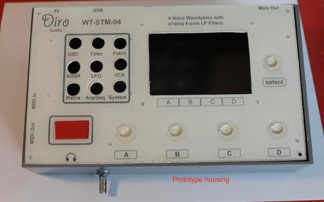
So my final setup:
2 PT8211 DAC’s (4 independent outputs)
10 buttons (one as encoder click)
5 encoders (one with click)
1 TFT ILI9341 with touch
1 OLED (shows the encoder function/values)
1 winbond SPI-EEPROM
1 23LC512 I2c-EEPROM (more write/erase cycles)
SD-Card (from TFT)
Serial MIDI
USB MIDI
all filter board controls via PWM (4x volume, 4x cutoff and 1x resonance (used for all voices, there is no need for 4 independent resos))
ST-link cable out (easiest way for updating)
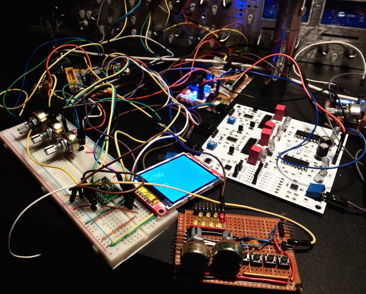
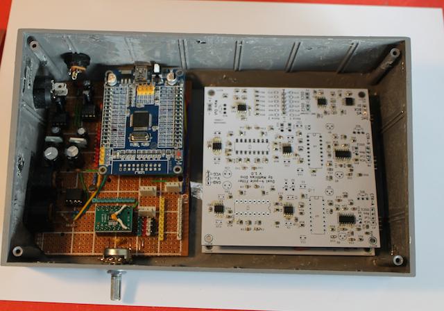
My filter boards arrived, I soldered them and then: Nothing. Spent all in all about 12 hours (Imagine: I have a wife, 3-year old daughter and a full time job, so time is *really* expensive for me) without solution. I was really thinking to give up even with all electronics.
Today I give myself another try, studied my kicad files, the original ones and datasheets and I found it:
Again a super silly nasty one: I confound one(!) 470R resistor with a 470pf cap. Error was also in my KICAD layout and everything stopped to work.
Ok, with the working filter board (I totally trashed the first one, for heavens sake dirtyPCB send you about 12 boards), I did some sound testing and mentioned, that with PWM there is no chance (3.3V versus 5V (filter board is for 5V)), so I have to use SPI-octal DAC’s (LT1660) no big deal, because I have a bunch of them at home, but a little bit nasty to program: SPI TFT (and SD) is on Div2 and the SPI-DAC’s need Div4. Tried many things and the best thing for stability (no hanging TFT or DAC) is to deal with Div4.
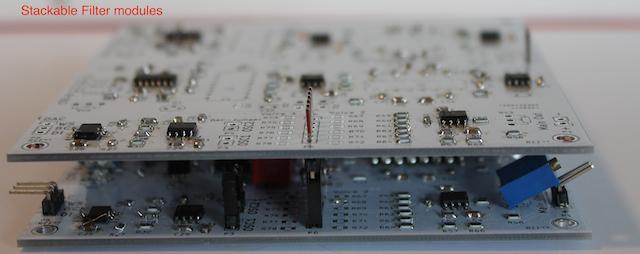
Some words about the sound of the filter board: Just *amazing* !!! Real analog 4-pole low pass with additional analog VCA on board. And the best: absolutely no noise! So all my doubts are gone….
Quick pic of the test setup, filter board is the white PCB:
I would love to see a video demonstration of your board when you finish it!
ps. I have a wife, two daugthers 13 and 11 years old, a full time job and I work in a chemical industry with three shifts. I know what means “free time” …
But… when you love something you can find some time for it ![]()
I would love to see a video demonstration of your board when you finish it!
UPDATE:
DAC – PWM
As I’ve written before, PWM as “analog control out” is no option for me (3.3 vs 5V and much too low PWM frequency), so I decided to use a SPI DAC LTC1660 (or LTC1665 (8 or 10 bit)).
But I have: 4x Cutoff, 4x Volume + a common channel for Resonance = 9 outputs. Sadly the LTC is only an octal DAC. Luckily the STM32F103RCT has 2 onboard DAC’s, but one (PA5) conflicts with the SPI SCK. But the other one is “clean”. So I have my 9 analog outputs
Display
I think I’m leaving the idea with a ILI9341 TFT, because of several reasons: Slow down the system, “oversized” – I don’t need colors for this project and it’s not really good to see in the sun (brightness, viewing angle). So I decided to use a big 128×64 monochrome display (ST7920, I wrote a library for this –> see main repo) as main display and a secondary I2C-OLED (printing values for the encoders).
RTOS
I think I’m done with RTOS for this project: I’ve too much troubles with it. Ok, maybe I can go into the deep with it, but this takes me too much time, and I didn’t have it.
Problems so far: My LCD S7920 graphic library won’t work with RTOS. Lines, boxes and other graphic elements are working, but the font is only garbage. Not even in the setup code I can use the font. So I think there must be a big memory conflict especially with libraries and bigger arrays (like fonts) (I did have this while using the adafruit ILI9341 library, but I raise the stack size for the task). Another reason is, that I can use about 90% of written code from my former project (with a tiva-tmc123) I handled everything with timers. Next deal: There is no real hardware timer integration in RTOS and the minimal delay is 1ms (I need ns). I’ve researched for both problems in RTOS forums, found many entries but no solution.
edit: Got the LCD library to work. Problem was a “static long xy” variable in another task (ok, it seems like RTOS doesn’t like static variables within tasks….)
But I have a question:
In the LCD library there are several delay(x) I think this doesn’t fit good with RTOS (vDelay) but I cannot handle that (tried to use vDelay in the library, but it wont function)
I did some testing rewritting the SPI library and the ILI9163 for CoOS, and had to do that. I haven’t tried with FreeRTOS, but I’m sure would be the same case.
That said, you can do it all with timers, there is no reason for RTOS. I would use an RTOS if it makes my life simpler, but not more difficult ![]()
The libmaple systick ISR can be set to callback your own function every 1ms, if that helps you schedule some tasks without using an RTOS, and then you can use any other timer at a much higher frequency for other stuff. Give than you dont need the timers for PWM, you should have plenty of timers for that.
About the audio, even if it is just white noise I would like to hear it, took us so many headaches to get the DMA I2S working!! ![]()
Ah one more thing, you can lock the RTOS scheduler during time sensitive functions, so it doesn’t deschedule a certain when you don’t want it to. I forgot the functions names, but there are 2, one to lock the scheduler and one to unlock it again. Interrupts would not be affected. You can do that to test if you suspect the scheduler is affecting your functions in any way, so you lock, run your time sensitive code, unlock again.
Mostly of the modules were built:
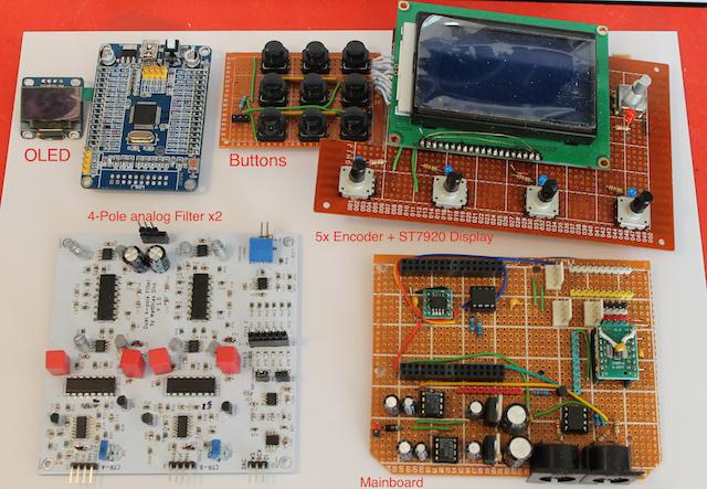
https://youtu.be/TVV4jb7tQec
https://youtu.be/TVV4jb7tQec
I kicked RTOS out of the project, only problems with the used libraries and I haven’t the time rewriting every single one, and I’m really better on timers with this project.
Ok, I managed to convert everything back, got interface running (encoders, knobs, leds’s…), got DMA Sound for all 4 channels running without clicks, all other DAC’s (for VCA, Cutoff…).
And NOW:
I added some more variables and functions and the whole fonts on the ST7920 display is GARBAGE. Everything is working ok, only the font is the problem: So printing lines, circles, everything is fine. So I guess there must be a memory leak and/or wrong pointers. But this occurs ONLY with the ST8920 library, not with the adafruit OLED, this is running clearly. So the more code (variables) I put into it, the more garbage come out, if I remove additional code the font becomes correct. Totally frustrating.
I believe there must be some mistakes with the conversation of the whole PROGMEM stuff from the original library, but I wont think that somebody here can help me out, but I put the library code here:
What I have done is to compare the font handling of the adafruit gfx and from my library (extern const… and so on) with no luck.
edit: there is “RTOS” in the name of the library, but there is no RTOS in there anymore.
regards
Matthias
<…>
So the more code (variables) I put into it, the more garbage come out, if I remove additional code the font becomes correct. Totally frustrating.
<…>
Matthias
Sketch uses 141,844 bytes (54%) of program storage space. Maximum is 262,144 bytes.
Global variables use 28,104 bytes of dynamic memory.
Sketch uses 141,844 bytes (54%) of program storage space. Maximum is 262,144 bytes.
Global variables use 11,720 bytes of dynamic memory.
But the same garbage on display. I think, the must be a pointer problem accessing the flash or something.
edit the font arrays are in flash (“extern const fontdata xy”)
There must be a really bad thing with “const” and pointers for the fonts (the whole font structure is a totally pointer and “struct” madness). The library isn’t ideal, but BAD LUCK: I’ve done the complete graphic interface with this piece of s….unshine including creating own fonts and characters.
I cannot use a adafruit library for this display (because there is none) . The only “universal library” support the ST7920 is the u8glib and I never will porting this monster to stm32duino, because it’s too big and wants support everything, so you need months to adapt the code. (The library is about 1mb!!).
The really bad joke is, that I adapted many display libraries since the beginning of the stm32duino project for the community and now I fail totally with my one.
Maybe I declare the font structure a little bit:
fonts are in a separate file:
Example: glcd5x5_STM.cpp
In this file:
#include "lcd7920_STM_RTOS.h"

const uint8_t glcd5x5_STM[]  = (...font data...)
<…>
The really bad joke is, that I adapted many display libraries since the beginning of the stm32duino project for the community and now I fail totally with my one.
<…>
But thanks for the suggestion with the glass of wine, I’m drinking 1/8 now and then I go asleep
const extern LcdFont font5x9_STM;
5×9 then…
lcd.setFont(&font13x14_STM);
13×14.. I’m confused, is it 5×5, 5×9, 13×14… or am I being a bit slow on the uptake here?
I just implemented Adafruit GFX_AS instead of using original driver fonts (and even graphic functions).
First test looks good, but I just tested a minimal code, so I’ve to bring it into my main code and rewrite the graphical interface. Hope, that’ll work.
Main benefit: Beside that I don’t have to use different fonts (for ST7920 and the OLED), the ST7920 library is ; more or less; totally compatible with all other adafruit display libraries (nearly 99% compared to the SSD1306, because of the same screen size) PLUS the benefit of the two individual hardware screen buffers (so I can write to one screen, while the other is displayed, like two virtual screens, but with the benefit that is build in in hardware, so really one command is needed to switching between them and not like all software versions, which just send the whole buffer to the display while switching). I think this was the best decision and it wasn’t – surprisingly – really no pain converting it!
For the community I’ll test the new library as I can and I’ll put it into the main repo. (I think I can optimize the “drawPixel” method a little bit).
![[Pending Enhancement] RTC values resetting](https://sparklogic.ru/wp-content/uploads/2019/11/nucleo-l476rg-zestaw-startowy-z-mikrokontrolerem-z-rodziny-stm32-stm32l476-90x90.jpg)