int outputPin = PA6; //output pin
void setup() {
// put your setup code here, to run once:
pinMode(outputPin, OUTPUT);
//or ? pinMode(out1, PWM);
Serial.begin(9600);
// ???
}
void loop() {
// put your main code here, to run repeatedly:
// 72 MHz dividing by 100 code ???
// Serial.println( ???);
// Serial.print (???); // print result of dividing, PWM on pin PA6
}
which simple code?
Maybe someone know how to write such code ?
one typical process would be to look up the datasheet and figure out how the clock division works.
another typical process would be to beg someone else to write it for you.
Three historical references:
http://docs.leaflabs.com/static.leaflab … timer.html
http://docs.leaflabs.com/static.leaflab … imers.html
http://docs.leaflabs.com/static.leaflab … timer.html
Forum discussion: http://forums.leaflabs.com/forums.leafl … ml?id=1361
HardwareTimer pwmtimer(3);
uint16_t maxduty, duty;

uint32_t myperiod, mypulse;
void setup() {

pwmtimer.pause();

myperiod = 20; // PWM period in useconds, 20 -> freq = 50KHz

maxduty = pwmtimer.setPeriod(myperiod);

pwmtimer.refresh();

pwmtimer.resume();

pinMode(PA7, PWM);

}
void loop() {

mypulse =  5; // 0<=mypulse<=period, this is my High pulse length in useconds

duty = map((int32_t)mypulse, 0, (int32_t)myperiod, 0, (int32_t)maxduty);

pwmWrite(PA7, duty); // 0<=duty<=maxduty

while(1){};

}
#include <SPI.h>

int outputPin = PA6; //output pin
void setup() {
// put your setup code here, to run once:
pinMode(outputPin, OUTPUT);
//or ? pinMode(out1, PWM);
Serial.begin(9600);
// ???
}
void loop() {
SPI.setClockDivider(SPI_CLOCK_DIV128);
Serial.println( ???);
// Serial.print (???); // print result of dividing, PWM on pin PA6
}
/*
SPI.setClockDivider(SPI_CLOCK_DIV16); // (72 MHz / 16 = 4.5MHz)
The SPI1 works on APB2 (72 MHz). The maximum frequency that works the SPI1 is 72/2 =36 MHZ.
The SPI2 works on APB1 (36 MHz). The maximum frequency that works the SPI2 is 36/2 =18 MHZ.
The available dividers are:
CODE: SELECT ALL
SPI_CLOCK_DIV2
SPI_CLOCK_DIV4
SPI_CLOCK_DIV8
SPI_CLOCK_DIV16
SPI_CLOCK_DIV32
SPI_CLOCK_DIV64
SPI_CLOCK_DIV128
SPI_CLOCK_DIV256
*/
div_100_a:17: error: ‘period’ was not declared in this scope
duty = map((int32_t)mypulse, 0, (int32_t)period, 0, (int32_t)maxduty);
^
exit status 1
‘period’ was not declared in this scope
output on PA7 = 550 Hz
Also I’ve tested the first source and it works here on BluePill.
The second source under investigation.
pwmtimer.setPrescaleFactor(4);       // Timer input clock Prescaler = 1 (= 36MHz input ?)

pwmtimer.setOverflow(0.5);            // PWM Period width for 720kHz ?
When I am compiling first version I have mentioned error
Frequency is 50 kHz, pulse with 25%.
I will play with numbers.
Big Thanks
It seems the input clock is 72MHz and I need “100-1” to get exact 720kHz (720.045kHz here)..
98  = 727.319 kHz

99  = 720.045 kHz

100 = 712.916 kHz

101 = 705.927 kHz
pwmtimer.setOverflow(100);            // PWM Period width for 720kHz ?

pwmtimer.setCompare(TIMER_CH2, 50);  // PWM High Pulse width is 50% duty (1:1)pwmtimer.setOverflow(100);            // PWM Period width for 720kHz ?

pwmtimer.setCompare(TIMER_CH2, 50);  // PWM High Pulse width is 50% duty (1:1)
Here you are Sir:
HardwareTimer pwmtimer(3);
void setup() {

pinMode(PA6, PWM);

pwmtimer.pause();

pwmtimer.setPrescaleFactor(1);       // Timer input clock Prescaler = 1 (= 72MHz input ?)

pwmtimer.setOverflow(10000-1);            // PWM Period width for 7200 Hz ?

pwmtimer.setCompare(TIMER_CH1, 5000);  // PWM High Pulse width is 50% duty (1:1)

pwmtimer.refresh();

pwmtimer.resume();

}
void loop() {

}
Can I have both frequencies, PA7 =720 kHz and PA6 = 7.2kHz ?
HardwareTimer pwmtimer3(3);

HardwareTimer pwmtimer2(2);
void setup() {

pinMode(PA7, PWM);

pwmtimer3.pause();

pwmtimer3.setPrescaleFactor(1);       // Timer input clock Prescaler = 1 (= 72MHz input ?)

pwmtimer3.setOverflow(100-1);            // PWM Period width for 720kHz ?

pwmtimer3.setCompare(TIMER_CH2, 50);  // PWM High Pulse width is 50% duty (1:1)

pwmtimer3.refresh();

pwmtimer3.resume();
pinMode(PA3, PWM);

pwmtimer2.pause();

pwmtimer2.setPrescaleFactor(1);       // Timer input clock Prescaler = 1 (= 72MHz input ?)

pwmtimer2.setOverflow(10000-1);            // PWM Period width for 7,2kHz ?

pwmtimer2.setCompare(TIMER_CH4, 5000);  // PWM High Pulse width is 50% duty (1:1)

pwmtimer2.refresh();

pwmtimer2.resume();

}
void loop() {

}
You may combine both to get 720k/7k on PA7/6.
You cannot combine Timer3 with 2 different pwm periods it seems.
You need two different timers as I have done above.. it works with PA7/PA3..
See the TimerX/ChannelY allocation – PWM3/2 means Timer3->Channel2:
.
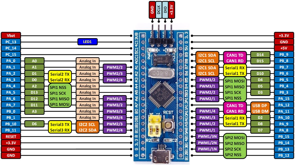
- STM32 BLuePill PIN diagram.JPG (209.41 KiB) Viewed 338 times
I will try that.
The last your code, PA7 = OK, PA6 = no signal
Is working perfect, I have 720 kHz and 7.2 kHz.
Thanks
Now I will take a close look to understand completely how this is working.
Some PWM TimerX/ChannelY pins are doubled – that means they can be remapped by sw.
There are nice people on the forum, just hard is to meet them.
1. For square wave we can use HIGH/LOW on pin instead PWM ?
2. One of PWM can generate sine wave on additional pin?
// Use timer 2

HardwareTimer pwmtimer2(2);
void setup() {
pinMode(PA3, PWM);
// pwmtimer2.pause();
pwmtimer2.setPrescaleFactor(100); // Timer input clock Prescaler = 1 (= 72MHz input ?)
pwmtimer2.setOverflow(100-1); // PWM Period width for 7,2kHz ?
pwmtimer2.setCompare(TIMER_CH4, 50); // PWM High Pulse width is 50% duty (1:1)
// pwmtimer2.refresh();
pwmtimer2.resume();
}
void loop() {
}
If not, I would recommend to leave those lines enabled, in case you wish to use the same sequence in other context they may be important.
Will disabling those lines make microcontroller less busy ?
I guess not much.
what is your image – aged sculpture ?
#1
function y = sin3(x)

n = 1 : 1000;

for i = 1 : length(x)

y(i) = x(i).*prod(1 - x(i)^2 ./ (n*pi).^2);

end
[ted – Wed Jan 03, 2018 1:03 pm] –
<…>
Will disabling those lines make microcontroller less busy ?
I guess not much.
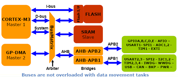
There is a danger to my not responding to this statement as it may be read and interpreted by a non-hardware user as meaning that within the uC, disabling peripheral interfaces will/would make the uC run faster. This is not the case.
If one studies the STM32 architecture document, one will note that the microcontroller has internal buses that connect various subsystems. Disabling a subsystem “may” reduce the chip power usage, but generally subsystems that are not utilized are not initialized and configured, so power dissipation of non-used peripherals should be minimal.
What does make a microcontroller “busy” is the start-up/initialization code and then user code that exercises the various peripheral activities. Some peripheral devices such as PWM consume bandwidth when they are configured but afterward do not consume any user execution time unless something is changed by user code. Of course, when PWM is active, electrical power is consumed because that device is active and clocking to an output pin.
/*

HardwareTimer pwmtimer(3);
void setup() {

pinMode(PA6, PWM);

pwmtimer.pause();

pwmtimer.setPrescaleFactor(1);       // Timer input clock Prescaler = 1 (= 72MHz input ?)

pwmtimer.setOverflow(10000-1);            // PWM Period width for 7200 Hz ?

pwmtimer.setCompare(TIMER_CH1, 5000);  // PWM High Pulse width is 50% duty (1:1)

pwmtimer.refresh();

pwmtimer.resume();

}
void loop() {

}

*/

HardwareTimer pwmtimer(3);
void setup() {

pinMode(PB4, PWM);

pwmtimer.pause();

pwmtimer.setPrescaleFactor(1);       // Timer input clock Prescaler = 1 (= 72MHz input ?)

pwmtimer.setOverflow(10000-1);            // PWM Period width for 7200 Hz ?

pwmtimer.setCompare(TIMER_CH1, 5000);  // PWM High Pulse width is 50% duty (1:1)

pwmtimer.refresh();

pwmtimer.resume();

}
void loop() {

}
PA7 uses the Timer 3 with Channel 2
PB4 uses the Timer 3 with channel 1 but it’s an alternate function (AFIO_TIM3_PARTIAL). you have to ensure the AF is set properly.
Probably you could try adding:
afio_remap(AFIO_REMAP_TIM3_PARTIAL);
Anyone hoping to be successful working with timers need to be familiar with the specific STM32 Reference Manual. Yes, it is a big PDF but it is also the bible for any aspiring engineer. Beyond the PDF, there are many smaller dissertations which will help provide some glue knowledge to help in understanding the details around timers. All commonly available references can be found with only a single Google query.
To everyone posting in the forum… THINK BEFORE YOU POST
In reviewing this thread, the Op has done what many of us do from time-to-time; that is, posted and then gone back and deleted a post.
In this case, several posts were deleted in sequence. A thread should be continuous in thought and response and deletes, especially multiple deletes, leaves the thread discontinuous and hard to follow. DO NOT DO THIS… If you must edit a prior post, then at least strike-through like this the old or add some key to let the reader know that the text was time-shifted, edited, amended, etc. Everyone is responsible for being a good citizen in the forum, so think before you post.

Ray
(Global Moderator)
fpiSTM – thanks for your suggestions, it not working yet, but is it some point to start.
Posts cant actually be deleted, the system just hides them.
Ray. does moderator privileges allow you to show them again, if not I’ll see if I can change the settings
As Ray mentioned, I think you should read the data sheet and do some search about Alternate function.
http://www.st.com/content/ccc/resource/ … 171190.pdf
See §9 General-purpose and alternate-function I/Os (GPIOs and AFIOs)
A GPIO pin can have several functions but not at the same time. Up to you to configure it depending of your need.
Software remapping of I/O alternate functions
To optimize the number of peripheral I/O functions for different device packages, it is possible to remap some alternate functions to some other pins. This is achieved by software, by programming the corresponding registers (refer to AFIO registers. In that case, the alternate functions are no longer
mapped to their original assignations
Can you help me to add a sine wave output to your code, maybe by combining A and B codes ?
Code A
HardwareTimer pwmtimer2(2);

void setup() {

pinMode(PA3, PWM);

pwmtimer2.pause();

pwmtimer2.setPrescaleFactor(10);

pwmtimer2.setOverflow(1000-1);

pwmtimer2.setCompare(TIMER_CH4, 500);

pwmtimer2.refresh();

pwmtimer2.resume();

}
[ted – Wed Feb 28, 2018 7:52 pm] –
Here is the drawing clarifying my question – why A is not equal B .
fpiSTM – thanks for your suggestions, it not working yet, but is it some point to start.
Those are alternate pins. The MCU allows you so select if a peripheral uses one pin OR another pin, but you can’t use 2 pins at the same time for the same function. It’s alternate, one or the other.
all that is in the reference manual, it’s long, but you should read thru it to understand the peripherals. No amount of QA in the forum will cover what the reference manual can teach you.
Furthermore, you can’t do a sine wave with PWM. The times can output 0 or 1, low or high, but not an analogous signal. You need a DAC for that, and the bluepill MCU doesn’t have a DAC, so no sine wave.

