I’m Carl
My first project with STM32 will hopefully be to get some code onto this GD32F103 board, and drive the LCD. I first need to figure out what the driver is. It appears to be using 17 pins.. Hopefully the ILI9341.
I will then use this as a screen / controller for my vehicle datalogger that I have already built on an Adafruit Feather M0.
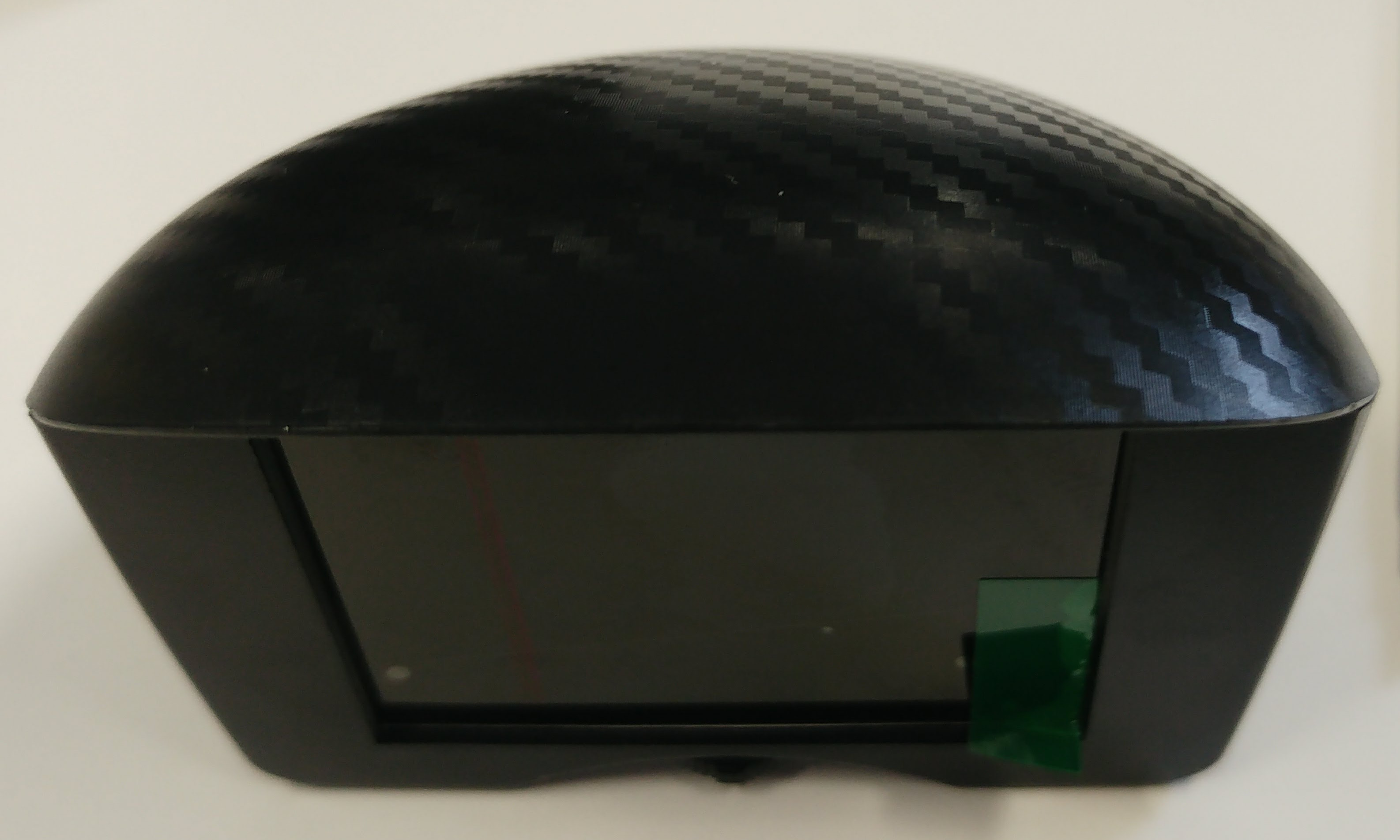
Here’s the thing I want to hack..
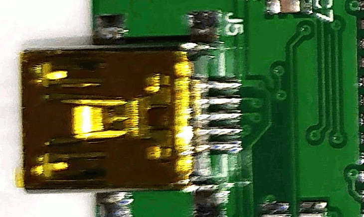
Note that the mini-USB on the back here is actually for a vehicle OBD connection, and will be expecting +12v as well as K-Line, L-Line, CAN-Hi/CAN-Lo, etc.. It’s *not* a Mini-USB connection!
(in most web browsers, you can right-click on the images below and choose Open Image in New tab, to view at full resolution).
I have given up trying to support the GD32 because we found it’s not really compatible with the STM32.
The GD32 is based on the spec for the STM32 but that’s where the similarities end.
Some things work but others don’t.
E.g. SPI didn’t seem to work quite the same. ( possibly some sort of Mode issue)
It did not work with that display.
There are various reasons why it’s not compatible, including use of “reserved” parts of the control registers , which means potentially lots of the GD32 enhanced functionality is not configured by the Core.
Also the program runs in shadow RAM not Flash, so executed considerably faster, which potentially causes timing issues.
I have left the GD32 variant folders in the F1 core, I simply removed the lines from boards.txt which enable the use of that Variant, so you could reinstate those lines.
However if something doesn’t work, you are likely to need to debug it at the hardware level to determine what’s going wrong.
You will also need to try to find some documentation on the GD32 and compare the hardware registers to see what may or may not have been configured
I recall at least a year ago a Russian website, where someone documented at least 20 differences between the GD32 and the STM32,but I susoect its almost impossible to find that information now, unless someone posted a link to this forum when the GD32 was initially launched
If you are a whiz with a hot air reflow tool, you could unsolder the GD32 and solder a STM32F103C8 in its place.
However I’ve tried to do that, and ended up pulling tracks of the board and ruining it ![]()
Its probably easier to get hold of another ribbon cable connector and a Blue Pill board and use that instead of the MCU board thats in that device.
My other problem is that I don’t really know what this display controller is yet.
I’ve just got OpenOCD talking to this board after tracing out the SWD pins, and.. well.. while I feel like I’ve made some progress (I have no idea what I’m doing really.. I have been able to halt, read registers, and reset the MCU, that’s all), I suppose I was hoping to try simply uploading some pre-built code for a 64-pin stm32f103 that’s connected to a ILI9341 via SPI and see if by some miracle it ran and displayed something on the screen.
OTOH, you’re quite right, I could spend ages trying to reverse engineer this undocumented thing, or I could instead have a proper plan with a blue pill. My time might be better spent now trying to figure out what’s going up/down the flat flex to the TFT LCD. I have a 4 channel scope and one of those cheap fake salae logic analysers so if it’s SPI I should be able to see that.
BTW, I am actually intending to use a slightly different version of this thing in the end. I had been searching high and low for an LCD inside a nice housing, ideally a gauge for a motorbike. 2 line dot matrix lcd would have done, and I was close to giving up. So to find this for 20 quid had been a joy. I’ve had to order the gauge style one from China, so in the meantime, I got this pod style one that I have dismantled, from Amazon. I am pretty sure they will be much the same inside. They have the same system running on them, same button/dial thingy.. supposedly made by the same company.

I guess mww in OpenOCD was writing to flash…
![]()
I would start by figuring out which pins the display is on, then flash some of the display demos to it and see if it does anything interesting.
If you do a bit of deep dive google trawling you may even be lucky enough to turn up the original firmware on some obscure Chinese forum, or file sharing site.
CPT CLAA024GUF1 Electronics Details
Driver IC : COG Built-in ST7789VI
http://www.allshore.com/pdf/ST7789V.pdf (older version of datasheet)
https://newhavendisplay.com/appnotes/da … T7789V.pdf
Probably being run in 8 bit parallel mode.
You would examine the ribbon cable and buzz out the pins on the main board to figure what goes where.
[RogerClark – Wed Apr 11, 2018 10:27 pm] –
If you are a whiz with a hot air reflow tool, you could unsolder the GD32 and solder a STM32F103C8 in its place.
However I’ve tried to do that, and ended up pulling tracks of the board and ruining it
Roger: About resolder a Chip:
I successfully resolder (and exchanged) a 1284A from my Melzi printer board with a common DIY store hot air gun (this thing for removing varnish):
- Wrap all not to resolder parts in tinfoil (several layer, loosely wrapped) only let the chip free.
Blow dry the chip upside down, it falls down after a while
Soldering the new chip: Use soldering paste! Spread it to the contacts of the layer, put the chip on it and use a hot air gun or a common soldering iron.
[ahull – Thu Apr 12, 2018 7:56 am] –
That display may be this -> http://www.panelook.com/CLAA024GUF1_CPT … 31211.htmlCPT CLAA024GUF1 Electronics Details
Driver IC : COG Built-in ST7789VIhttp://www.allshore.com/pdf/ST7789V.pdf (older version of datasheet)
https://newhavendisplay.com/appnotes/da … T7789V.pdfProbably being run in 8 bit parallel mode.
You would examine the ribbon cable and buzz out the pins on the main board to figure what goes where.
Hi Andy. Thanks for that. I’m new to all this, but I think I follow..
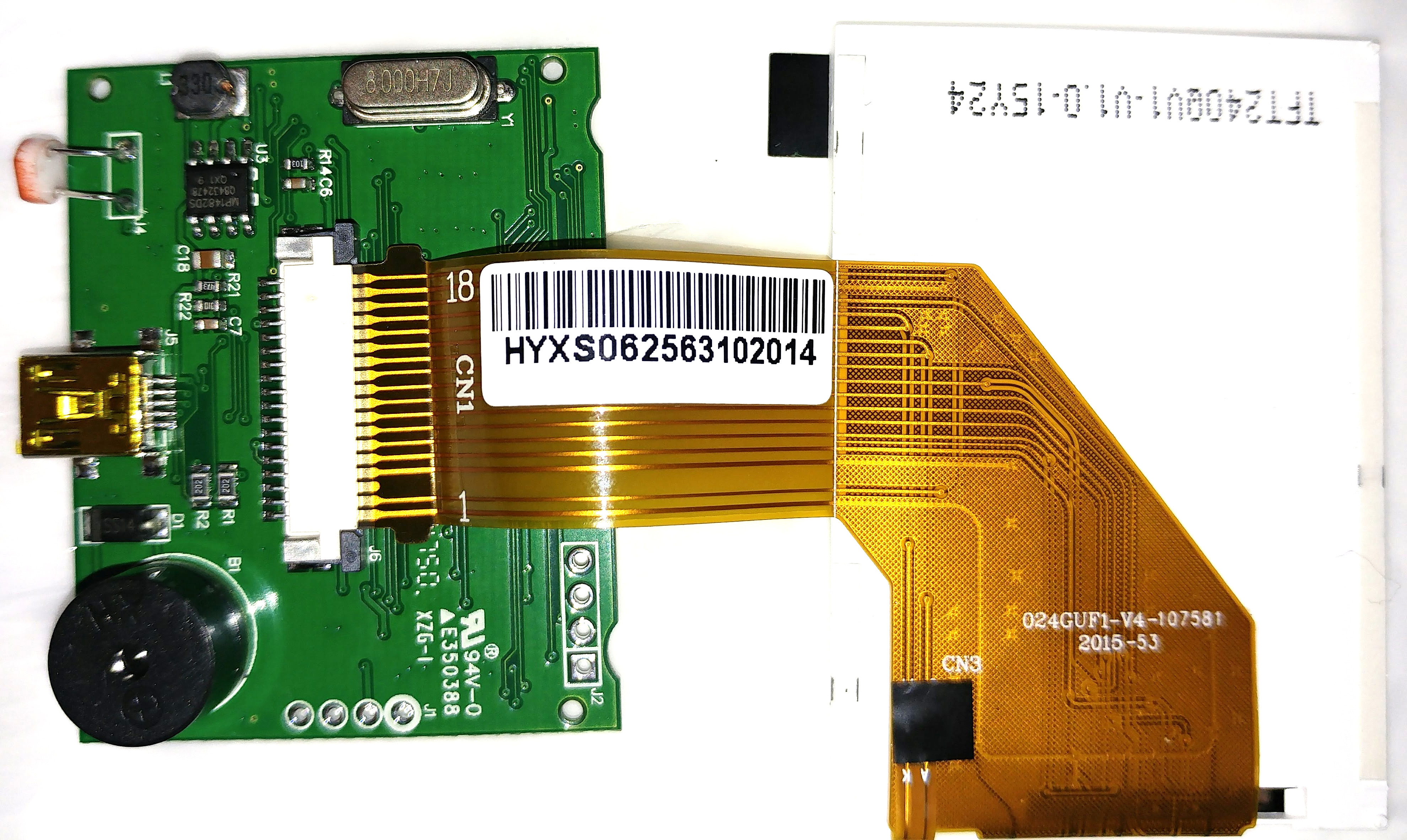
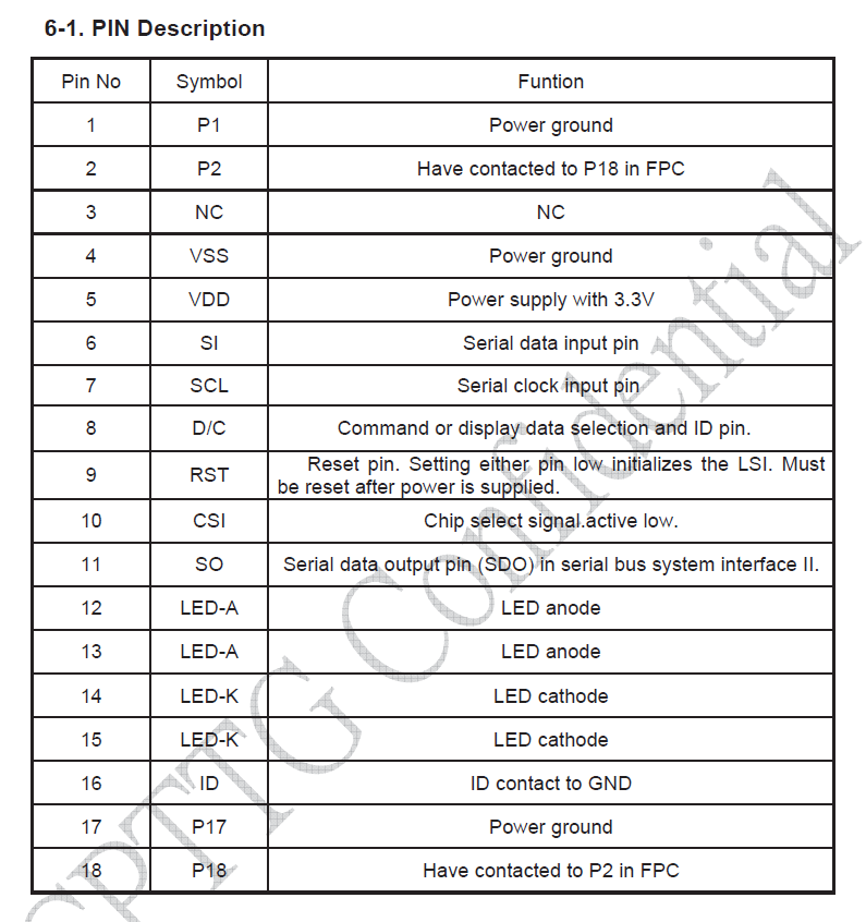
8 bit parallel 8080-I mode would use 8 data lines (d0 – d7), and the 5 control lines (RDX, WRX, D/CX, CSX, and RESX), which is 13 wires, plus maybe another 2 – 4 for backlight? It is clear from the ribbon that 2 wires do not go directly to the display controller chip. They seem to span off into a separate run of FFC (labelled as CN3 on the FFC). We have CN1 = 1 to 18, with one dummy / missing on the end, CN2 = 1 to 96, going to the display controller, with some density of connections just slightly to the left middle of the driver IC, and CN3 = 2 connections going to the top edge of the LCD, where I think some passives are located.
What makes you think it could be the ST7789BVI rather than the ILI by the way?
Good idea about the aluminium foil.
I know I didnt get it hot enough.
[RogerClark – Wed Apr 11, 2018 10:27 pm] –
I think if enough time was spent on the GD32 it could be made to work, but because there were so few GD32 boards available, there was hardly anyone with a board who had the time and skillset to resolve the problems
I’m obviously mistaken about this, given that you guys support the Blue Pill, but not GD32, but.. I thought I had read somewhere that these sub-$2 stm32f103 boards ‘must be using re-badged STM clones to be so cheap (i.e. GD32)’.
I guess that’s not the case?
[ahull – Thu Apr 12, 2018 7:56 am] –
That display may be this -> http://www.panelook.com/CLAA024GUF1_CPT … 31211.htmlCPT CLAA024GUF1 Electronics Details
Driver IC : COG Built-in ST7789VIhttp://www.allshore.com/pdf/ST7789V.pdf (older version of datasheet)
https://newhavendisplay.com/appnotes/da … T7789V.pdfProbably being run in 8 bit parallel mode.
You would examine the ribbon cable and buzz out the pins on the main board to figure what goes where.
Hey Andy.. I didn’t notice PanelLook let you get datasheets (only 1 though..! without paying).
I got the datasheet but it says the panel is SPI only.
http://www.internetsomething.com/autool … 24GUF1.pdf
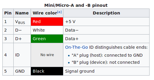
It does look to be that panel though – good work – thanks! The not-connected pin-3 matches exactly.
The GD32 is quite a different device.
It’s functional is was copied from the STM32 data sheet, but GigaDevices added some enhancements.
They also didn’t manage to completely duplicate the functionality in the spec. ( they have bugs in the hardware)
GigaDevices have a license to use the Arm core of the processor, so they are not breaking any laws by doing what they did.
It’s mainly used by companies in China who are developing products from scratch and they use the GD32 standard peripheral library files supplied by GigaDevices.
The BluePill etc all use official ST32 chips.
[RogerClark – Thu Apr 12, 2018 11:18 am] –
We asked ST and they are not aware of any clones of the STM32.The GD32 is quite a different device.
It’s functional is was copied from the STM32 data sheet, but GigaDevices added some enhancements.
They also didn’t manage to completely duplicate the functionality in the spec. ( they have bugs in the hardware)
GigaDevices have a license to use the Arm core of the processor, so they are not breaking any laws by doing what they did.It’s mainly used by companies in China who are developing products from scratch and they use the GD32 standard peripheral library files supplied by GigaDevices.
The BluePill etc all use official ST32 chips.
I see, thanks. I did see a post on here where somebody explained a few of the errata/differences, in particular I remember that SPI has to be selected between master or slave, which isn’t necessary on STM32, and a couple other things.. Think there was a list of 8 or so things but they didn’t sound big.
I want to try to get some code onto this thing anyway. I have ordered a ‘bluepill’. I’m not sure it will physically fit inside my round gauge that I have on order though. An adafruit Itsy M0 will fit.. but, that’s another £12 when I already have a more powerful MCU here, with CAN transceivers and all sorts of other gubbins built in. Plus, connecting to this 18-pin FFC on the screen is going to be a PITA if I use another board.
[ahull – Thu Apr 12, 2018 7:56 am] –
That display may be this -> http://www.panelook.com/CLAA024GUF1_CPT … 31211.html
It is 100% that panel! the CAD drawing has the same part number on it!!
How did you find that? I can’t even find it when I search panellook.com for “18 pin” or “18pin” etc. ?? Thanks so much.
Would you believe though, that there are no 18-pin FFC breakout boards available anywhere? They go 10, 12, 14 ,16, 20… etc.!!
I have ordered some 18 pin FFC connectors and some 20 pin breakout PCBs to solder them to, but this is another reason why it would be easier if I could use the existing MCU & board.
To do that, we would need to reverse engineer the PCB a bit.
We need to know which pins go where on between the GD and the LCD.
Once we know that, we can try some of the existing ST7789BVI examples although they may need a little tweaking to get them to work on the GD rather than the STM. If you are up for a lot of probing with your multimeter and a fair amount of head scratching, I suspect we can get it to work.
The LCD also has a backlight, for which we need to identify the pin(s). It is probably driven via PWM and one of those transistors.
This is probably the first thing we need to identify as reading the display is going to be pretty difficult without the backlight ![]()
I cant make out the writing on all of the chips on your board, can you identify the numbers on them all?
Do you have an ebay/Aliexpress/Taobao listing for the one you bought, and that other one you linked a picture of?
[ahull – Thu Apr 12, 2018 1:29 pm] –
It would be more interesting to use the existing GD CPU too and a much cleaner solution.To do that, we would need to reverse engineer the PCB a bit.
We need to know which pins go where on between the GD and the LCD.
Once we know that, we can try some of the existing ST7789BVI examples although they may need a little tweaking to get them to work on the GD rather than the STM. If you are up for a lot of probing with your multimeter and a fair amount of head scratching, I suspect we can get it to work.
The LCD also has a backlight, for which we need to identify the pin(s). It is probably driven via PWM and one of those transistors.
This is probably the first thing we need to identify as reading the display is going to be pretty difficult without the backlight

I cant make out the writing on all of the chips on your board, can you identify the numbers on them all?
Do you have an ebay/Aliexpress/Taobao listing for the one you bought, and that other one you linked a picture of?
I’m definitely up for that! ![]()
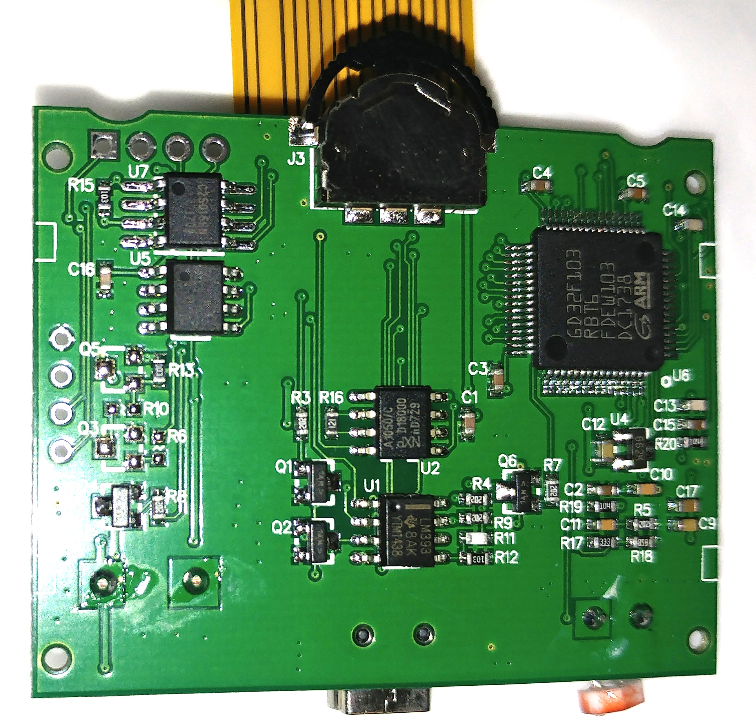
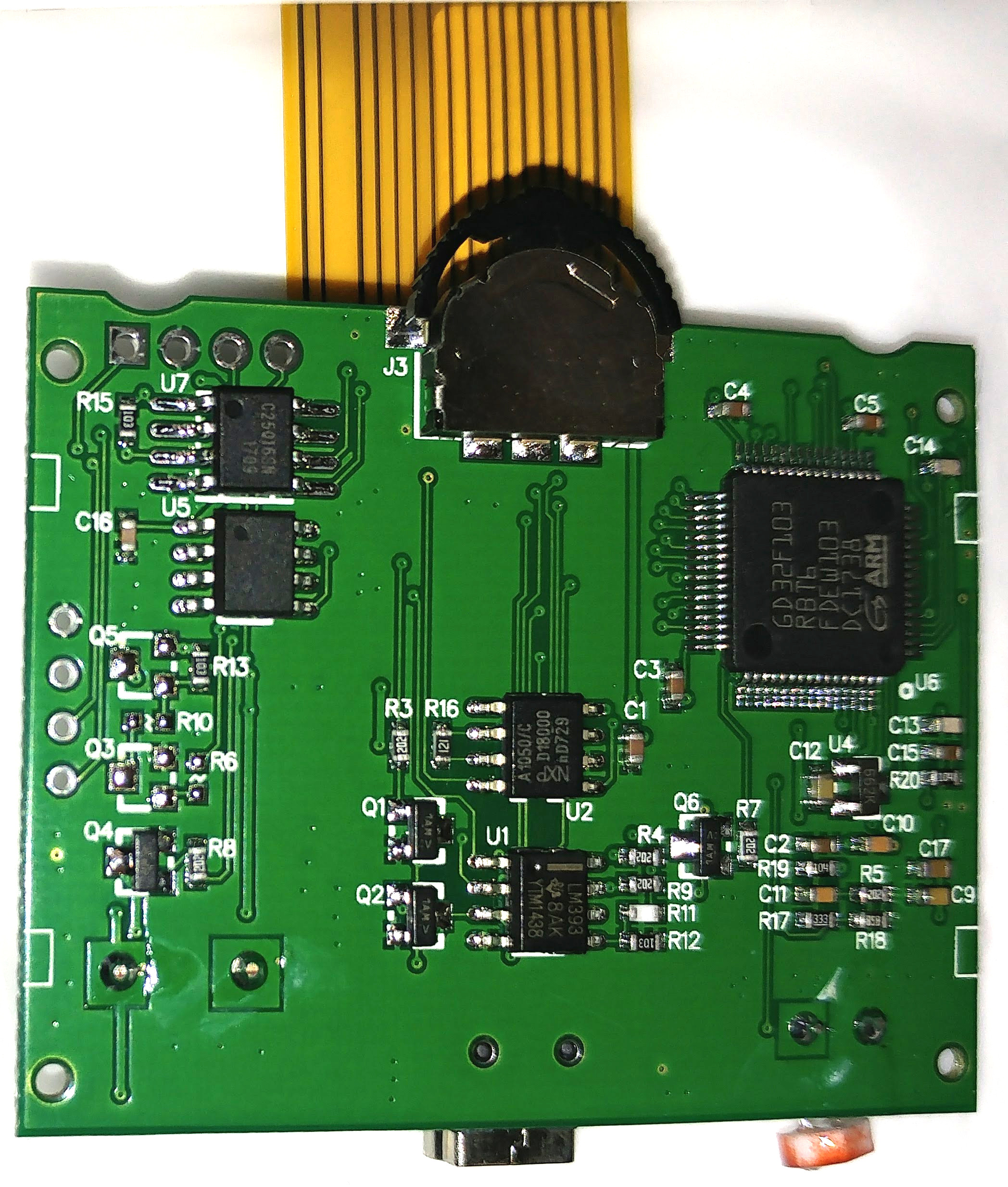
There’s only one un-labelled chip. You can get a breakdown of the chips here: http://brano2.blogspot.co.uk/2017/09/ro … -auta.html
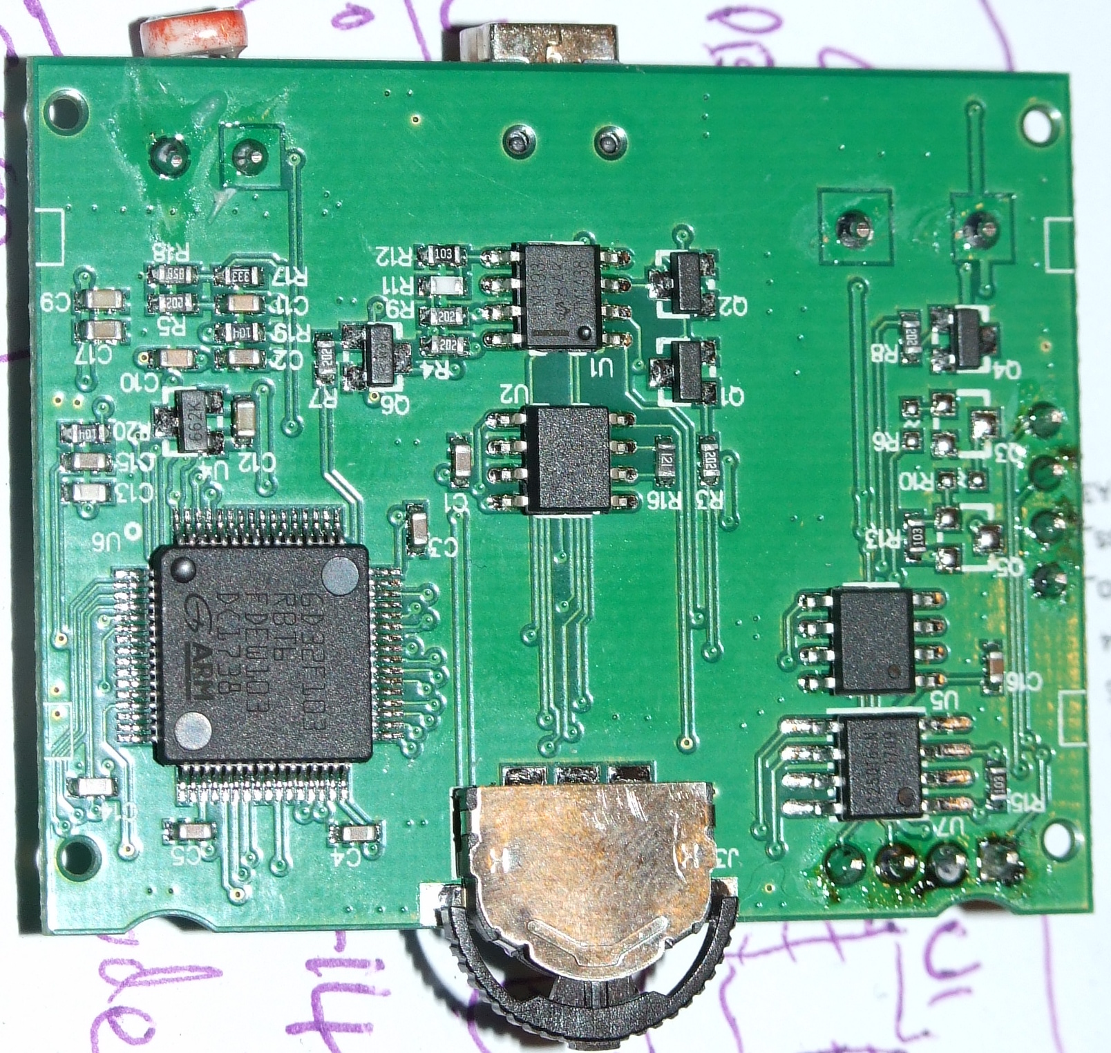
The circuit board includes the following integrated circuits:
U1 LM393 (K, L-line conversion)
U2 TJA1050 (HS-CAN transceiver 5V)
U3 MP1482DS (step-down 2A, sync rectified)
U4 LM6206N3 (linear voltage stabilizer 1,5-3,3V 0,25A ozn 662k)
U5?
U6 GD32F103RBT6 ARM Cortex-M3 3.3V 36-45mA 128KB flash, 20KB sram, usb2.0, can2.0b, case LQFP64
U7 S25FL216KIF pdf (2MB serial flash 3V)
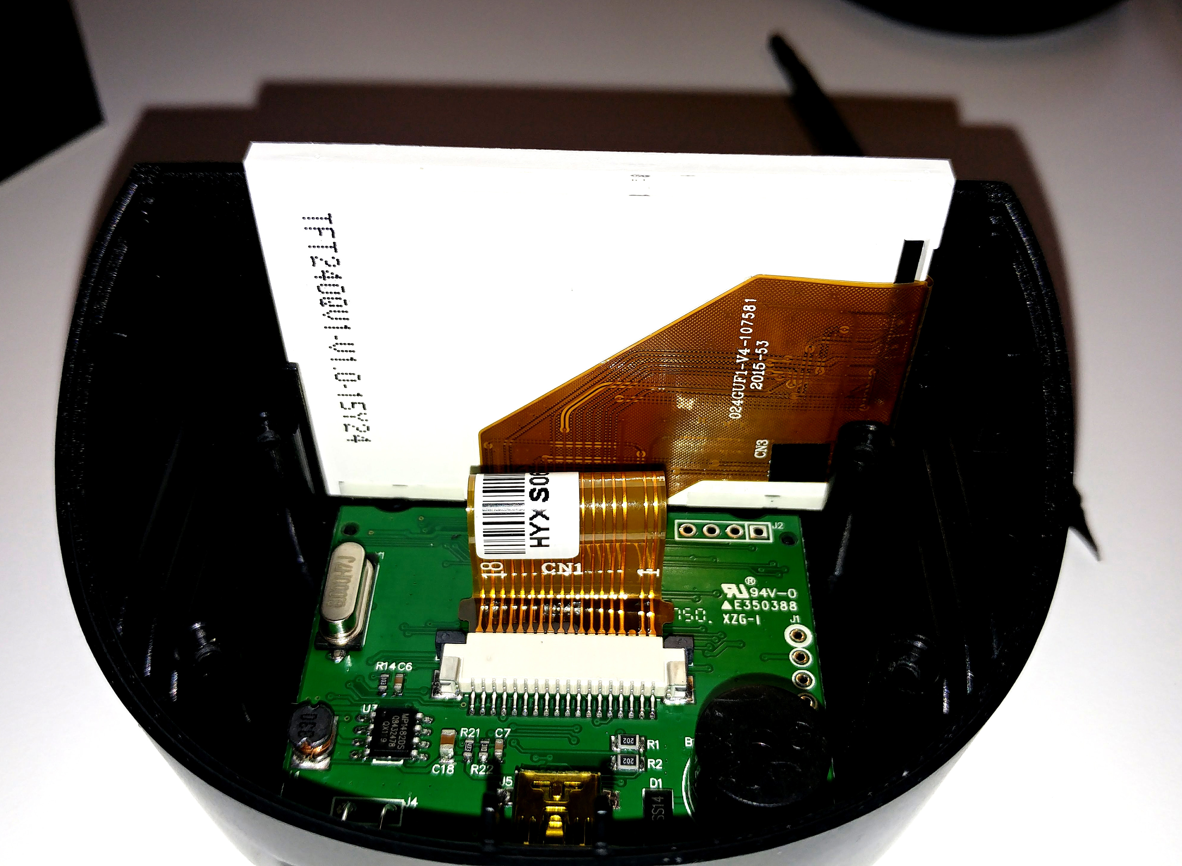
Top of the printed circuit board From the inner (top) side of the link, there is an 8MHz crystal, a buzzer, a connector for the display.
As described, this is a version 4.3. From the top to the right is a J1 connector that contains 3.3 / 5V serial output from the processor (either I2C bus number 2, or Rx / Tx USART3).
At the top right is the J2 connector that is used to program the flash memory.
Here are the write-protect, gnd, SI / IO and SCK signals from the U7 external flash memory SPI.
The display connector has 18 pins, 13 used for LCD screen, 4 for LED backlighting and one unused.
The display shows the TFT240QV1-V1.0-15Z01, the 024guf1-v4-207581 2015-53 cable, the white label HYXS062563103752 on the cable.
except that on mine, the 2MB serial flash is a different chip for which I can find no data, and I was unable to read it in-circuit with my SOFI SP8A. Maybe that’s expected with it still being on the board though.
I was at it ’til 3:30am this morning. I’m not sure the girlfriend will allow that again tonight, but I’ll keep the thread updated. Thanks for your assistance and encouragement.
[carl0s – Thu Apr 12, 2018 11:42 am] –
How did you find that? I can’t even find it when I search panellook.com for “18 pin” or “18pin” etc. ?? Thanks so much.
I searched for 024GUF1 which is stamped on the FPC cable. There is often little difference between these displays except the layout of the ribbon cable, so that can often be the best of the many random numbers stamped on the display to search for. I’ve had similar success looking for displays for old Canon cameras in the past.
I was a little disappointed that I didn’t turn up more info, for example some mass produced consumer device like a camera or GPS that used that exact display, but I didn’t spend much time on the task, so you may get luck and find more info if you keep trawling.
[ahull – Thu Apr 12, 2018 1:37 pm] –[carl0s – Thu Apr 12, 2018 11:42 am] –
How did you find that? I can’t even find it when I search panellook.com for “18 pin” or “18pin” etc. ?? Thanks so much.I searched for 024GUF1 which is stamped on the FPC cable. There is often little difference between these displays except the layout of the ribbon cable, so that can often be the best of the many random numbers stamped on the display to search for. I’ve had similar success looking for displays for old Canon cameras in the past.
I was a little disappointed that I didn’t turn up more info, for example some mass produced consumer device like a camera or GPS that used that exact display, but I didn’t spend much time on the task, so you may get luck and find more info if you keep trawling.
Thanks Andy.
You could also try “ST7789V Interface I8080”. You never know you might turn up an exact clone of the display you have.
Regarding the flash chip, try holding the GD32 in reset using an ST-LinkV2 clone while probing the external flash chip, in case the GD32 is hogging the bus and stopping your reader from working. If all else fails you could of course unsolder it, but that might be a little tricky. I only tend to indulge in surgery if the patient absolutely requires it, or is already dead ![]()
There are a lot of very similar devices from different manufacturers, with similar pinouts, so you may simply have not quite the correct parameters.
Put your multimeter in diode test mode, and probe between the A and K pins, and you may well be rewarded with a dim glow from the backlight.
From there it is a matter of figuring out where those pins go on the main pcb.
Look closely at the image you posted of the FPCB, the interface might actually be relatively easy to figure out.
Although the controller has a bewildering array of possible interface modes, we can eliminate most of them due to the relatively low number of pins on the connector.
The connector itself has 18 pins, and one of those has been left blank, so that leaves 17, if we assume a minimum of two further pins, one each for power and gnd, and it appears two pins for the LED (although it may have a common ground or power pin, so it may only use one), then we only have 13 pins left, so we cant be using 16 bit parallel modes. It may be possible to further eliminate pins, since we may have a ground pin interleaved between each signal pin. If this is the case, then we may only be looking at six or seven signal lines.
If the gadget was still working, we could stick a logic analyser on it and get the right answer pretty quickly, but since it is not, we may need to eliminate the remaining modes by trial and error.
I presume the display doesn’t have a touch screen.
The button interface should also be relatively easy to figure out with the continuity tester on your multimeter too.
[ahull – Thu Apr 12, 2018 3:05 pm] –
The backlight is pretty easy to identify. Look for the A and K pins on the FPCB (ribbon cable). They are almost certainly (A)node and (K)athode of the LED(s), furthermore the black tape (labelled CN3 on the FPCB) probably covers an SMD LED (or two) or a couple of zero ohm links. One other possibility is that the black tape might cover some configuration jumper pads used to set the interface mode.Put your multimeter in diode test mode, and probe between the A and K pins, and you may well be rewarded with a dim glow from the backlight.
From there it is a matter of figuring out where those pins go on the main pcb.Look closely at the image you posted of the FPCB, the interface might actually be relatively easy to figure out.
Although the controller has a bewildering array of possible interface modes, we can eliminate most of them due to the relatively low number of pins on the connector.
The connector itself has 18 pins, and one of those has been left blank, so that leaves 17, if we assume a minimum of two further pins, one each for power and gnd, and it appears two pins for the LED (although it may have a common ground or power pin, so it may only use one), then we only have 13 pins left, so we cant be using 16 bit parallel modes. It may be possible to further eliminate pins, since we may have a ground pin interleaved between each signal pin. If this is the case, then we may only be looking at six or seven signal lines.
If the gadget was still working, we could stick a logic analyser on it and get the right answer pretty quickly, but since it is not, we may need to eliminate the remaining modes by trial and error.
Well, as it happens I ordered another one of the same gadgets at 3am this morning. Should have it tomorrow ![]()
If read-out protection isn’t set, I’ll read the flash and write it back to my broken one.
I can get my USB L/A on it.
Here are the FFC pinouts, so i guess it’s just a matter of finding which SPI pins on the GD they are connected to.
You could could try just selecting the Generic STM32F103C board, if your board uses an 8MHz crystal ( I think from the photos that it does)
Note, don’t select the F103CB as the GD32F103C8 only every has 64k Flash unlike the STM chip where you normally get 128k even on the 64k version ( because ST’s production yields are so good they don’t have duff chips to sell as the 64k version )
However getting the display to work would involve debugging the SPI at the hardware level using a logic analyser
It’s a actually a shame that the companies in China who made the GD32 boards, initially charged so much for them, and then ceased production due to lack of demand, as I think most people would have been happy to use the GD32 as it’s much faster than the STM32.
However perhaps the internal market in China found the GD32 was not as compatible as it was claimed to be, and hence it didn’t get the demand they expected for those boards.
E.g. No one has noticed any STLink dongles or other similar boards appearing with GD32 MCUs on them.
So the price / risk ratio of the GD32 can’t make it economic for the manufacturers in China to widely use it
I can’t see any incentive for most companies to use it.
The GD32 would need to be reasonably cheaper eg. Half the price of the STM32 to make economic sense to take the risk on a new device.
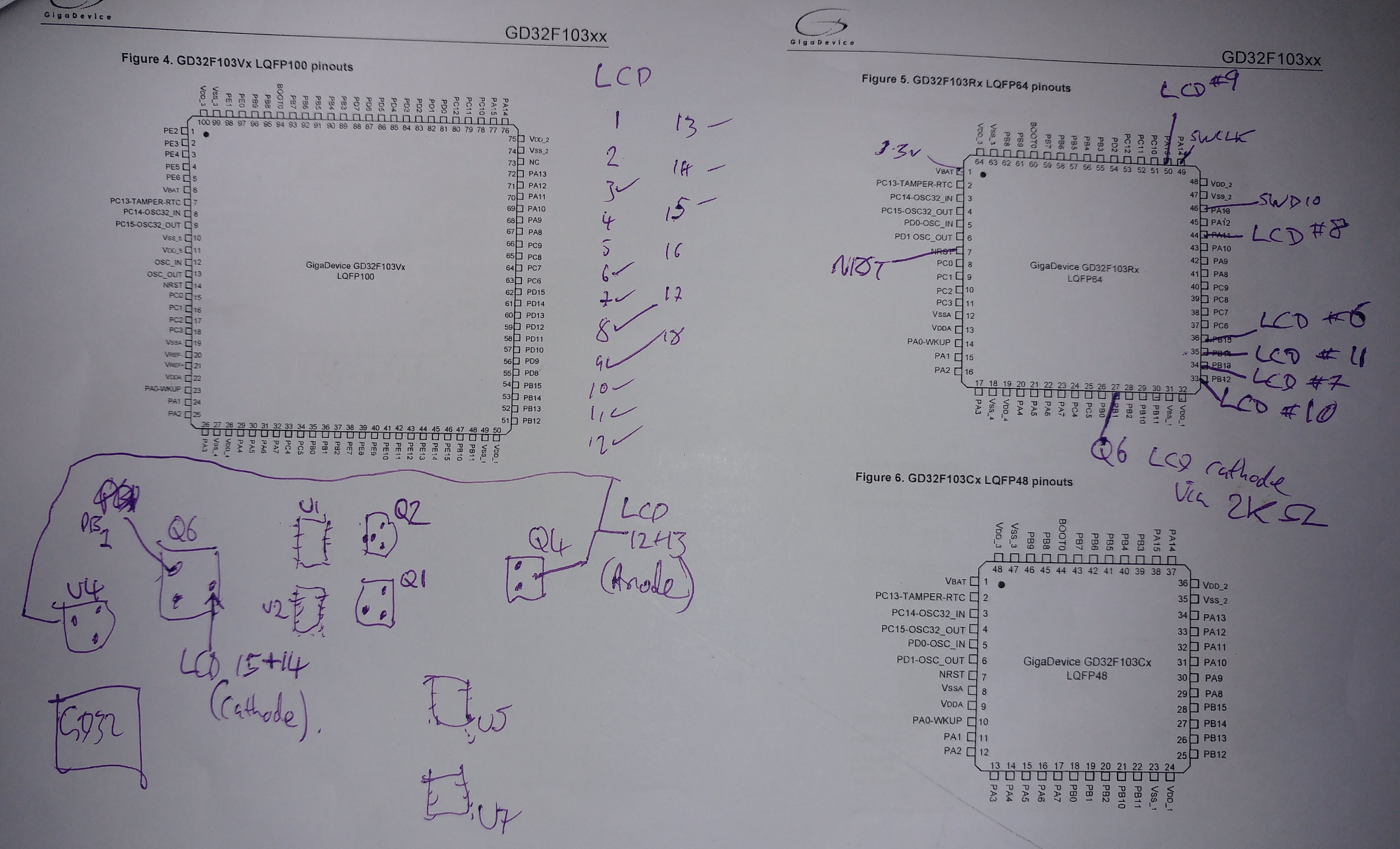
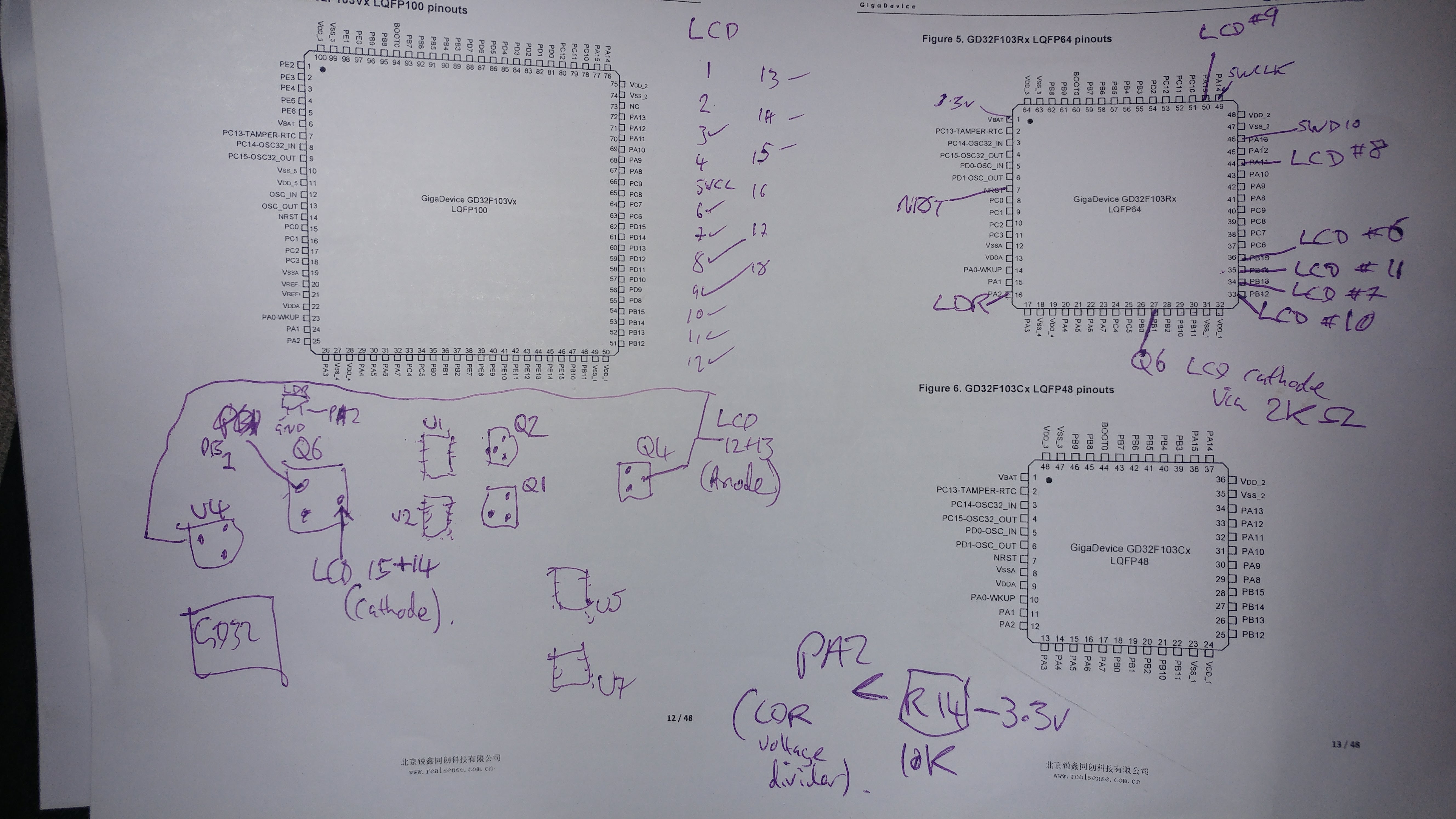
Anyway I have the datasheet for both the LCD and the LCD driver, and I have buzzed out all the pins tonight, and it all makes sense. The screen is connected to PB12 to PB15 (Alt mode: SPI2). The cathode pins (both) of the LCD backlight run via a 2.2k ohm resistor from PB1 thru a transistor of some sort (Q6 on PCB). I’m a bit clueless and only just learning electronics but I get that a transistor is a switch..
Data/Command select (LCD FFC PIN8 in table above) is connected to PA11. LCD reset (FFC #9 in table above) is connected to PA15.
I’ll diagram all this up over the weekend with better PCB photos.
Its hard to know how they are marketing the GD32. I forget how much faster it is. Possibly 25% faster at best.
Strangely the GD32 has the option to run at 120Mhz with USB functioning, however the chip is only spec’ed to run at 108Mhz, and to maintain USB the speed has to drop down to 96Mhz. So it looks like their manufacturing quality or silicon fab design, didn’t live up to their initial spec’s
[carl0s – Thu Apr 12, 2018 10:29 pm] – The screen is connected to PB12 to PB15 (Alt mode: SPI2). The cathode pins (both) of the LCD backlight run via a 2.2k ohm resistor from PB1 thru a transistor of some sort (Q6 on PCB). I’m a bit clueless and only just learning electronics but I get that a transistor is a switch..
If we set up a blink sketch on PB1, we should be rewarded with a flashing backlight. The backlight I’m guessing, should draw about 30mA (for simplicity we can consider it as a single LED with the two x 2.2k resistors in parallel, but it is in reality probably a number of small LEDs in parallel with each other, seriesed up with each resistor) and should be quite bright at that. We can then try using PWM on that pin, which should give us full control of the backlight brightness.
I suspect from the description that setting the pin high will switch the backlight off, and low will switch it on, but I could of course be completely wrong. ![]()
Can you post a link to where you bought it ?
(I assume you bought it online ??)
Using the ebay search string “X50 plus car”
Cheapest I can find on ebay.com is :-
https://www.ebay.com/itm/AUTOOL-X50-Plu … SwvKtY9XXl
Best UK Price £17.21
https://www.ebay.co.uk/itm/AUTOOL-X50-P … SwvKtY9XXl
I cant be absolutely certain it is the same device as the “ANCEL A202 Smart OBDII Gauge Car Speed Meter” but the pictures look close enough to suggest 99.9% it is probably the same device. The display looks the same, and it has the same LDR and USB connector on the rear, the same jog/click button on the front etc.
EDIT: Just found this in the instructions.
” 7.Instrument standby time-After the car flames out, the set value is reached, and X50 Plus will sleep automatically.”
Don’t say you weren’t warned ![]()
[ahull – Fri Apr 13, 2018 10:00 am] –
This gadget seems to have several names, and several variants.Using the ebay search string “X50 plus car”
Cheapest I can find on ebay.com is :-
https://www.ebay.com/itm/AUTOOL-X50-Plu … SwvKtY9XXl
Best UK Price £17.21
https://www.ebay.co.uk/itm/AUTOOL-X50-P … SwvKtY9XXl
I cant be absolutely certain it is the same device as the “ANCEL A202 Smart OBDII Gauge Car Speed Meter” but the pictures look close enough to suggest 99.9% it is probably the same device. The display looks the same, and it has the same LDR and USB connector on the rear, the same jog/click button on the front etc.
EDIT: Just found this in the instructions.
” 7.Instrument standby time-After the car flames out, the set value is reached, and X50 Plus will sleep automatically.”
Don’t say you weren’t warned

Haha, yes that’s the correct device!
I will actually be using the Autool X60 in the end though which is a round gauge style, but I could only find those from China. So I got the above instead from Amazon (for £29.99 .. but I wanted it next day on prime!)
What they mean in the instructions there, is that because a car’s +12v in the OBD connector is constantly live (there’s no switched live available on OBD connector), it will instead go to sleep when the read values from OBD show that the engine has been off for a set time.
[ahull – Fri Apr 13, 2018 5:48 am] –[carl0s – Thu Apr 12, 2018 10:29 pm] – The screen is connected to PB12 to PB15 (Alt mode: SPI2). The cathode pins (both) of the LCD backlight run via a 2.2k ohm resistor from PB1 thru a transistor of some sort (Q6 on PCB). I’m a bit clueless and only just learning electronics but I get that a transistor is a switch..If we set up a blink sketch on PB1, we should be rewarded with a flashing backlight. The backlight I’m guessing, should draw about 30mA (for simplicity we can consider it as a single LED with the two x 2.2k resistors in parallel, but it is in reality probably a number of small LEDs in parallel with each other, seriesed up with each resistor) and should be quite bright at that. We can then try using PWM on that pin, which should give us full control of the backlight brightness.
I suspect from the description that setting the pin high will switch the backlight off, and low will switch it on, but I could of course be completely wrong.
I just need to find out how to build/compile stm32duino code and then upload it with my ST Link v2. I have been using PlatformIO for my Arduino stuff to date.
[ahull – Fri Apr 13, 2018 5:48 am] –[carl0s – Thu Apr 12, 2018 10:29 pm] – The screen is connected to PB12 to PB15 (Alt mode: SPI2). The cathode pins (both) of the LCD backlight run via a 2.2k ohm resistor from PB1 thru a transistor of some sort (Q6 on PCB). I’m a bit clueless and only just learning electronics but I get that a transistor is a switch..If we set up a blink sketch on PB1, we should be rewarded with a flashing backlight. The backlight I’m guessing, should draw about 30mA (for simplicity we can consider it as a single LED with the two x 2.2k resistors in parallel, but it is in reality probably a number of small LEDs in parallel with each other, seriesed up with each resistor) and should be quite bright at that. We can then try using PWM on that pin, which should give us full control of the backlight brightness.
I suspect from the description that setting the pin high will switch the backlight off, and low will switch it on, but I could of course be completely wrong.
There’s only one 2.2k resistor that I can see for the backlight by the way (R7). The 18-pin LCD FFC has two LED anodes and two LED cathodes, but they seem to be connected together. So both cathodes go to transistor Q6, which is then connected to the GD32 via 2.2K resistor R7.
The anodes are joined as well, and come out of transistor Q4, which also feeds V-in of voltage regulator U4 (662k – https://www.mikrocontroller.net/attachm … 6206N3.pdf )
Here is the PCB, and here is my drawing on the datasheet. My really bad drawing in the bottom left of the datasheet is the same orientation as the PCB, and I have diagrammed the important LCD pins. The only pins I haven’t bothered with are mostly ground and +vcc.
Also, here is the datasheet for the GD32F103 in English: http://www.internetsomething.com/autool … asheet.pdf
Here is the 850 page user guide for the GD32F103 in English: http://www.internetsomething.com/autool … N_V2.0.pdf
and here’s the LCD datasheet again: http://www.internetsomething.com/autool … 24GUF1.pdf
What about the switches for left/right/click interface and the LDR, have you identified these yet?
[ahull – Fri Apr 13, 2018 12:10 pm] –
Good progress.
What about the switches for left/right/click interface and the LDR, have you identified these yet?
No but I will do ![]()
The Autotool X60 looks to be almost identical (its “round” display may actually be a square one in a round bezel). It will be interesting to compare the two.
What they mean in the instructions there, is that because a car’s +12v in the OBD connector is constantly live (there’s no switched live available on OBD connector), it will instead go to sleep when the read values from OBD show that the engine has been off for a set time.
Oh.. so no real flames in that “flame out…” shame… I’ll tell the Trumpton fire brigade to stand down then ![]()
Yes I am expecting it to be a square display, but, I want a gauge style case ![]()
I used PlatformIO, and just chose “STM32F103R8 (20k RAM. 64 Flash)” as the board.
I didn’t realise it came with the OBD connector etc.
[carl0s – Fri Apr 13, 2018 9:19 pm] –
eeeeeee it works
Blinkey flashey stuff! ![]() Next up.. the display I would guess. That may take a bit more head scratching.
Next up.. the display I would guess. That may take a bit more head scratching.
You could also try reading the LDR, and using that to control the brightness of the backlight.
[ahull – Sat Apr 14, 2018 9:00 am] –[carl0s – Fri Apr 13, 2018 9:19 pm] –
eeeeeee it worksBlinkey flashey stuff!
You could also try reading the LDR, and using that to control the brightness of the backlight.
I have bought a working replacement unit. I was going to return it now that I can see the firmware is readout locked. Do you think I should keep it?
I was hoping there would be a gfx library for the display controller and I might just have to alter spi pin assignments or something. Is that a bit optimistic ? ![]()
Also, do you think I should set about getting a serial debugging console going for doing a lot of Serial.print() stuff? If so should I use the gd32’s on-chip usb or should I just use its uarts with a TTL to usb into my computer?
I probed the LDR last night so I have the pins. This is where I think serial debugging might help me though. Also I don’t yet know about pwm on these things. I hope you can set hardware to do it and just adjust when needed, as software pwm would surely eat up a huge number of cycles and require that absolutely no delays or blocking code happens anywhere during the main loop.
https://www.adafruit.com/product/3787
You should be able to compare how that works with say the STM32Duino Adafruit_ILI9341_STM examples. I think the two controllers are similar.
I think you can control the backlight with analaogWrite, so something like.. (untested)..
#define TFT_LED PB1

#define LRD_PIN {whatever you discovered}

...

...

pinMode(TFT_LED, OUTPUT);

analogWrite(TFT_LED, 127);

...
etc.
[ahull – Sat Apr 14, 2018 9:38 am] –
The display should be relatively easy to interface. In fact Adafruit did (still do?) an ST7789 based displayhttps://www.adafruit.com/product/3787
You should be able to compare how that works with say the STM32Duino Adafruit_ILI9341_STM examples. i think the two controllers are similar.
I think you can control the backlight with analaogWrite, so something like.. (untested)..
#define TFT_LED PB1

#define LRD_PIN {whatever you discovered}

...

...

pinMode(TFT_LED, OUTPUT);

analogWrite(TFT_LED, 127);

...
etc.
- Screenshot from 2018-04-14 11-02-30.jpg (106.66 KiB) Viewed 349 times
[ahull – Sat Apr 14, 2018 10:01 am] –
All five pins of the USB connector go *somewhere*, or at least there are tracks leading off to vias on the PCB. It would be useful to know where exactly they go.
Screenshot from 2018-04-14 11-02-30.jpg
I will trace them out. But the cable supplied has mini usb on one end, and a 16 pin OBD2 connector on the other. So there will be can hi, can low, K-line, maybe L-line (both iso 9141, L-line usually not needed), gnd, and +12v I expect.
[carl0s – Sat Apr 14, 2018 10:08 am] –[ahull – Sat Apr 14, 2018 10:01 am] –
All five pins of the USB connector go *somewhere*, or at least there are tracks leading off to vias on the PCB. It would be useful to know where exactly they go.
Screenshot from 2018-04-14 11-02-30.jpgI will trace them out. But the cable supplied has mini usb on one end, and a 16 pin OBD2 connector on the other. So there will be can hi, can low, K-line, maybe L-line (both iso 9141, L-line usually not needed), gnd, and +12v I expect.
EDIT: None the less, it would be interesting to see which pins go where. We may be able to make use of some of the pins on that weird USB connector for our own purposes. I vaguely recall he STM32 uses the same memory area for USB and CAN, and perhaps even the same pins. If there is some active circuitry in the cable, the USB port might actually have D+ and D- wired directly to the GD32.. in which case, you never know, you may be able to use the USB connector as a USB connector. I would check for high voltages coming out of it before I risked plugging it in to a PC of course.
It is possible that the high voltages have to be switched on in software, and the port may therefore power up like a USB port, and go in to ODB mode only when the software instructs it to.
[ahull – Sat Apr 14, 2018 10:10 am] –[carl0s – Sat Apr 14, 2018 10:08 am] –[ahull – Sat Apr 14, 2018 10:01 am] –
All five pins of the USB connector go *somewhere*, or at least there are tracks leading off to vias on the PCB. It would be useful to know where exactly they go.
Screenshot from 2018-04-14 11-02-30.jpgI will trace them out. But the cable supplied has mini usb on one end, and a 16 pin OBD2 connector on the other. So there will be can hi, can low, K-line, maybe L-line (both iso 9141, L-line usually not needed), gnd, and +12v I expect.
None the less, it would be interesting to see which pins go where. We may be able to make use of some of the pins on that weird USB connector for our own purposes.
Yes true. I was thinking the same.. change out the canbus or lm393 (used for k line) for something else maybe.
I’d recommend you pick the Generic stm32f103c8 and STLink
Run the driver installer
upload then upload any sketch with USB connected to the to the PC.
And see if anything appears in Windows device manager
[RogerClark – Sat Apr 14, 2018 10:38 am] –
I think if you select STLink upload it still keeps USB serial enabled, as STLink dongles do not have serial USB built into themI’d recommend you pick the Generic stm32f103c8 and STLink
Run the driver installer
upload then upload any sketch with USB connected to the to the PC.
And see if anything appears in Windows device manager
Thanks Roger I will try after I have found a usb hub to isolate it from my laptop’s usb ports. I just tried running it (the working unit) off the car cigarette lighter adapter that runs my dashcam and there were no signs of life. No beep or screen on.
- Screenshot from 2018-04-14 11-47-33.png (23.64 KiB) Viewed 204 times
[ahull – Sat Apr 14, 2018 11:07 am] –
I suspect D+ and D- probably go (directly or indirectly) to PA11 and PA12 since these are the pins for both USB-/USB+ and CANrx/CANtx
CAN Rx and CAN Tx have to go via a CAN transceiver chip. It’s chip U2 on the board.
Indeed, but the output of U2 doesn’t necessarily need to go to the D+ and D- pins of the USB connector.
Since VBus does not seem to be present, that leaves potentially four pins of the five, (the other being GND) that we haven’t really mapped.
I still think it would be interesting to follow those tracks from the USB connector to see where they go.
Here’s what I have so far, if you can even follow it.
Here’s one thing I don’t understand. The LDR. It goes GND->LDR->PA2<-R14(10k)<-3.3v.
I get that this is a voltage divider and that’s how PA2 can read the value of the LDR. What I don’t get, is why does the value that my multimeter shows for R14 vary from 7k to 8k depending on whether I have the LDR covered or not? I have my meter right across R14. 10k is the value printed on it.
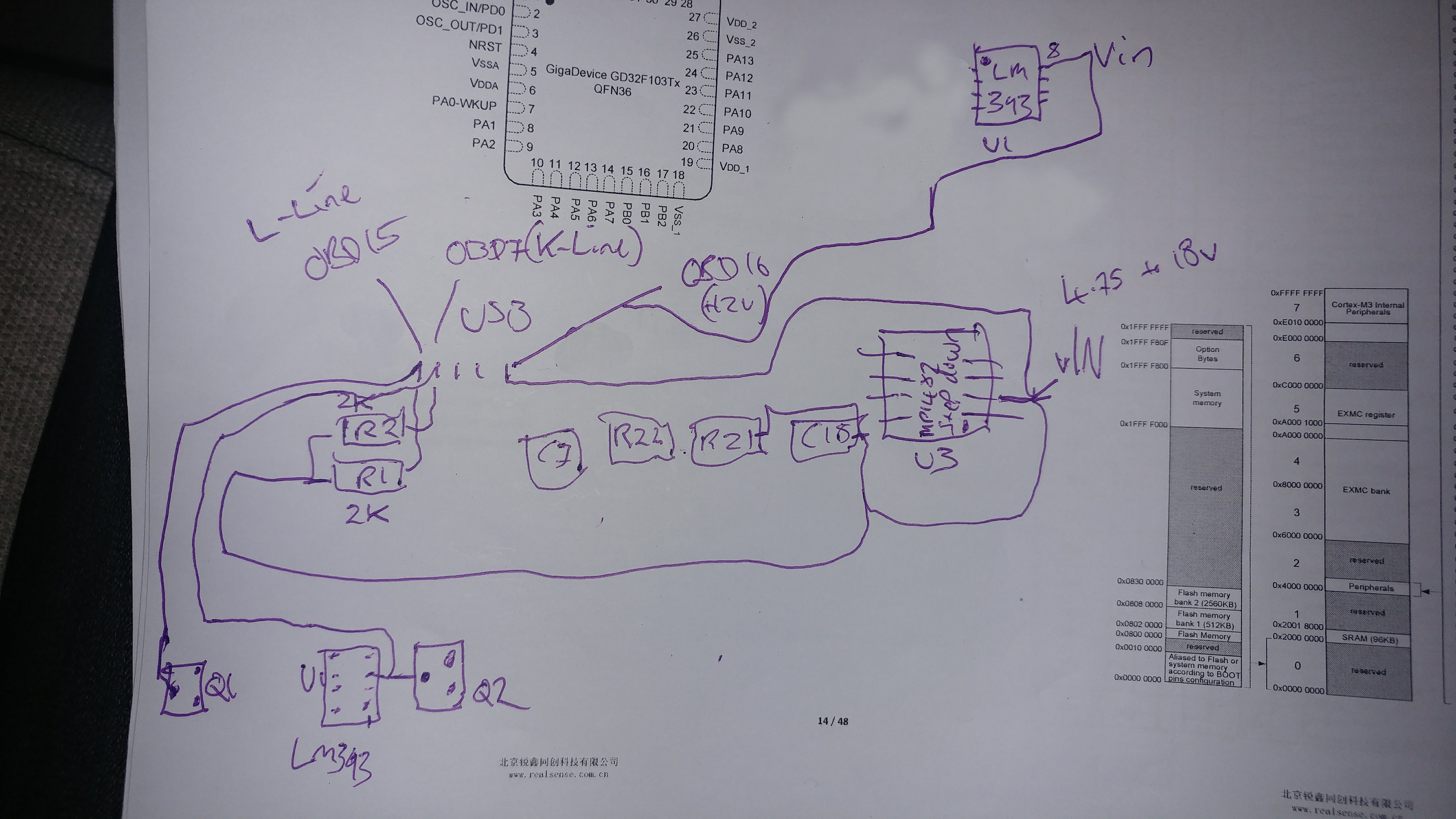
As you can see, I have put U1 (LM393 comparator, used for K/L line iso9141), in two places on the diagram. I’m off to Tesco for a beer, then I’m going to check out Fritzing.
Nevermind. I think DipTrace is the one to go for.
Non of the CAD packages are easy, but KiCAD is open source and favoured by most people on the forum
[RogerClark – Sun Apr 15, 2018 11:56 am] –
Use KiCADNon of the CAD packages are easy, but KiCAD is open source and favoured by most people on the forum
I have installed KiCad. I’ll give it a look. I am a big open source libre fanatic. DipTrace was looking easy because it has LQFP64 stm32 parts in there already and is reasonably priced for what looks to be high quality software.
Maybe I can download LQFP-64 stm32 components for KiCad. The stm32f407 lqfp-64 parts seem to have almost identical pin names/numbers to the lqfp-64 F103
I am currently trying to get my head around transistors.. I know it should be simple, but I’ve never tried to understand before.
The buzzer (piezo) on this board seems to have its +ve wired to the output of the main step-down IC (MP1482).
Its -ve is wired to the Collector of a general purpose NPN transistor (1AM).
The base of that NPN transistor goes through a 2K resistor R8 to PB6 of the MCU
and the emitter goes to GND.
How does that work then? NPN transistor is switched on with PB6 goes High (because that’s how NPNs work apparently?). Does that then just switch collector <-> emitter on. Are the Collector and Emitter back to front in this, or does it not matter?
Sorry for the elementary questions.
I guess you have to PWM a buzzer..
Using relative values should be doable without necessarily knowing the exact numbers coming from the ADC.
If you are a bit of a masochist you could of course blink out the numbers in Morse code ![]()
People have blinked out entire firmware dumps this way, but I don’t think we are quite that desperate.
http://chdk.wikia.com/wiki/Blinking_the … _interface
[ahull – Sun Apr 15, 2018 1:58 pm] –
I guess we just need to know what the trend is with the LDR, i.e. if it sees less light, we need to increase the LCD brightness and vice versa so if ADC value increases, brightness decreases (assuming the LDR is set up that way). The range of a typical LDR is quite broad, so anything from a few hundred ohms in bright light to perhaps a megohm or more in total darkness.Using relative values should be doable without necessarily knowing the exact numbers coming from the ADC.
If you are a bit of a masochist you could of course blink out the numbers in Morse code

People have blinked out entire firmware dumps this way, but I don’t think we are quite that desperate.
http://chdk.wikia.com/wiki/Blinking_the … _interface
![]()
Yeah I’ll come back to this one. I’ve tried dividing by 4 (since analogRead goes up to 1023, and analogWrite goes up to 254 ?) and also dividing by 2, but I don’t see any change. My DMM shows that the voltage goes between about 1v in living room, to between 1.5 or 1.8 v when the LDR is covered. I don’t have enough hands to test with a flashlight on it!
Needless to say it doesn’t work, however, this TFT is connected up to SPI2 on pins PB12 to PB15), which fits in with Vassilis wrote here: viewtopic.php?t=278
I can’t really see anywhere where (if at all) I need to amend the STM32Duino ILI9341 library for SPI2 instead of SPI1 though. It looks like it just configures SPI on whatever pins are set in the main program. Any thoughts?
oooh. setModule.
For 1v5 ….. (1.5/3.3)*1023=465
to 1v8 ….. (1.8/3.3)*1023=558
… so a range of 93 units.
So we could do something pretty rough to calculate a suitable analogWrite value for the backlight like like subtract our value from 570 and double it.
Crude, but probably we will see some effect (and since we are using multiplication rather than division, code safe since we can’t divide by zero).
However I do have version of the Pig-O-scope code that I ran on a GD32 board a long time back, which might give some clues, see below.
/*.

(c) Andrew Hull - 2015
STM32-O-Scope - aka "The Pig Scope" or pigScope released under the GNU GENERAL PUBLIC LICENSE Version 2, June 1991
https://github.com/pingumacpenguin/STM32-O-Scope
Adafruit Libraries released under their specific licenses Copyright (c) 2013 Adafruit Industries. All rights reserved.
*/
#include "Adafruit_ILI9341_STM.h"
#include "Adafruit_GFX_AS.h"
// Be sure to use the latest version of the SPI libraries see stm32duino.com - http://stm32duino.com/viewtopic.php?f=13&t=127
#include <SPI.h>
#define PORTRAIT 0
#define LANDSCAPE 1
// Define the orientation of the touch screen. Further
// information can be found in the UTouch library documentation.
#define TOUCH_SCREEN_AVAILABLE
#define TOUCH_ORIENTATION LANDSCAPE
#if defined TOUCH_SCREEN_AVAILABLE
// UTouch Library
// http://www.rinkydinkelectronics.com/library.php?id=56
#include <UTouch.h>
#endif
// Initialize touchscreen
// ----------------------
// Set the pins to the correct ones for your STM32F103 board
// -----------------------------------------------------------
//
// STM32F103C8XX Pin numbers - chosen for ease of use on the "Red Pill" and "Blue Pill" board
// Touch Panel Pins
// T_CLK T_CS T_DIN T_DOUT T_IRQ
// PB12 PB13 PB14 PB15 PA8
// Example wire colours Brown,Red,Orange,Yellow,Violet
// -------- Brown,Red,Orange,White,Grey
#if defined TOUCH_SCREEN_AVAILABLE
UTouch myTouch( PB12, PB13, PB14, PB15, PA8);
#endif
// RTC and NVRam initialisation
#include "RTClock.h"
RTClock rt (RTCSEL_LSE); // initialise
uint32 tt;
// Define the Base address of the RTC registers (battery backed up CMOS Ram), so we can use them for config of touch screen and other calibration.
// See http://stm32duino.com/viewtopic.php?f=15&t=132&hilit=rtc&start=40 for a more details about the RTC NVRam
// 10x 16 bit registers are available on the STM32F103CXXX more on the higher density device.
#define BKP_REG_BASE (uint32_t *)(0x40006C00 +0x04)
// Defined for power and sleep functions pwr.h and scb.h
#include <libmaple/pwr.h>
#include <libmaple/scb.h>
// #define NVRam register names for the touch calibration values.
#define TOUCH_CALIB_X 0
#define TOUCH_CALIB_Y 1
#define TOUCH_CALIB_Z 2
// Time library - https://github.com/PaulStoffregen/Time
#include "Time.h"
#define TZ "UTC+1"
// End RTC and NVRam initialization
// SeralCommand -> https://github.com/kroimon/Arduino-SerialCommand.git
#include <SerialCommand.h>
/* For reference on STM32F103CXXX
variants/generic_stm32f103c/board/board.h:#define BOARD_NR_SPI 2
variants/generic_stm32f103c/board/board.h:#define BOARD_SPI1_NSS_PIN PA4
variants/generic_stm32f103c/board/board.h:#define BOARD_SPI1_MOSI_PIN PA7
variants/generic_stm32f103c/board/board.h:#define BOARD_SPI1_MISO_PIN PA6
variants/generic_stm32f103c/board/board.h:#define BOARD_SPI1_SCK_PIN PA5
variants/generic_stm32f103c/board/board.h:#define BOARD_SPI2_NSS_PIN PB12
variants/generic_stm32f103c/board/board.h:#define BOARD_SPI2_MOSI_PIN PB15
variants/generic_stm32f103c/board/board.h:#define BOARD_SPI2_MISO_PIN PB14
variants/generic_stm32f103c/board/board.h:#define BOARD_SPI2_SCK_PIN PB13
*/
// Additional display specific signals (i.e. non SPI) for STM32F103C8T6 (Wire colour)
#define TFT_DC PA0 // (Green)
#define TFT_CS PA1 // (Orange)
#define TFT_RST PA2 // (Yellow)
// Hardware SPI1 on the STM32F103C8T6 *ALSO* needs to be connected and pins are as follows.
//
// SPI1_NSS (PA4) (LQFP48 pin 14) (n.c.)
// SPI1_SCK (PA5) (LQFP48 pin 15) (Brown)
// SPI1_MOSO (PA6) (LQFP48 pin 16) (White)
// SPI1_MOSI (PA7) (LQFP48 pin 17) (Grey)
//
#define TFT_LED PA3 // Backlight
#define TEST_WAVE_PIN PB1 // PWM 500 Hz
// Create the lcd object
Adafruit_ILI9341_STM TFT = Adafruit_ILI9341_STM(TFT_CS, TFT_DC, TFT_RST); // Using hardware SPI
// LED - blinks on trigger events - leave this undefined if your board has no controllable LED
// define as PC13 on the "Red/Blue Pill" boards and PD2 on the "Yellow Pill R"
#define BOARD_LED PB0
// Display colours
#define BEAM1_COLOUR ILI9341_GREEN
#define BEAM2_COLOUR ILI9341_RED
#define GRATICULE_COLOUR 0x07FF
#define BEAM_OFF_COLOUR ILI9341_BLACK
#define CURSOR_COLOUR ILI9341_GREEN
// Analog input
#define ANALOG_MAX_VALUE 4096
const int8_t analogInPin = PB1; // Analog input pin: any of LQFP44 pins (PORT_PIN), 10 (PA0), 11 (PA1), 12 (PA2), 13 (PA3), 14 (PA4), 15 (PA5), 16 (PA6), 17 (PA7), 18 (PB0), 19 (PB1)
float samplingTime = 0;
// Variables for the beam position
uint16_t signalX ;
uint16_t signalY ;
uint16_t signalY1;
int16_t xZoomFactor = 1;
// yZoomFactor (percentage)
int16_t yZoomFactor = 200;
int16_t yPosition = -150 ;
// Startup with sweep hold off or on
boolean triggerHeld = 0 ;
unsigned long sweepDelayFactor = 1;
unsigned long timeBase = 100; // Timebase in microseconds
// Screen dimensions
int16_t myWidth ;
int16_t myHeight ;
//Trigger stuff
boolean notTriggered ;
// Sensitivity is the necessary change in AD value which will cause the scope to trigger.
// If VAD=3.3 volts, then 1 unit of sensitivity is around 0.8mV but this assumes no external attenuator. Calibration is needed to match this with the magnitude of the input signal.
int32_t triggerSensitivity = 20;
int16_t retriggerDelay = 10;
int8_t triggerType = 1;
//Array for trigger points
uint16_t triggerPoints[2];
// Serial output of samples - off by default. Toggled from UI/Serial commands.
boolean serialOutput = false;
// Create Serial Command Object.
SerialCommand sCmd;
// Create USB serial port
USBSerial serial_debug;
// Samples - depends on available RAM 6K is about the limit on an STM32F103C8T6
// Bear in mind that the ILI9341 display is only able to display 240x320 pixels, at any time but we can output far more to the serial port, we effectively only show a window on our samples on the TFT.
# define maxSamples 1024*6
uint32_t startSample = 10;
uint32_t endSample = maxSamples ;
// Array for the ADC data
//uint16_t dataPoints[maxSamples];
uint32_t dataPoints32[maxSamples / 2];
uint16_t *dataPoints = (uint16_t *)&dataPoints32;
// End of DMA indication
volatile static bool dma1_ch1_Active;
#define ADC_CR1_FASTINT 0x70000 // Fast interleave mode DUAL MODE bits 19-16
void setup()
{
// BOARD_LED blinks on triggering assuming you have an LED on your board. If not simply dont't define it at the start of the sketch.
#if defined BOARD_LED
pinMode(BOARD_LED, OUTPUT);
digitalWrite(BOARD_LED, HIGH);
delay(1000);
digitalWrite(BOARD_LED, LOW);
delay(1000);
#endif
serial_debug.begin();
delay(1000);
serial_debug.println("# STM-32-Oscope started.");
delay(1000);
adc_calibrate(ADC1);
adc_calibrate(ADC2);
setADCs(); //Setup ADC peripherals for interleaved continuous mode.
//
// Serial command setup
// Setup callbacks for SerialCommand commands
sCmd.addCommand("timestamp", setCurrentTime); // Set the current time based on a unix timestamp
sCmd.addCommand("date", serialCurrentTime); // Show the current time from the RTC
sCmd.addCommand("sleep", sleepMode); // Experimental - puts system to sleep
#if defined TOUCH_SCREEN_AVAILABLE
sCmd.addCommand("touchcalibrate", touchCalibrate); // Calibrate Touch Panel
#endif
sCmd.addCommand("s", toggleSerial); // Turns serial sample output on/off
sCmd.addCommand("h", toggleHold); // Turns triggering on/off
sCmd.addCommand("t", decreaseTimebase); // decrease Timebase by 10x
sCmd.addCommand("T", increaseTimebase); // increase Timebase by 10x
sCmd.addCommand("z", decreaseZoomFactor); // decrease Zoom
sCmd.addCommand("Z", increaseZoomFactor); // increase Zoom
sCmd.addCommand("r", scrollRight); // start onscreen trace further right
sCmd.addCommand("l", scrollLeft); // start onscreen trae further left
sCmd.addCommand("e", incEdgeType); // increment the trigger edge type 0 1 2 0 1 2 etc
sCmd.addCommand("y", decreaseYposition); // move trace Down
sCmd.addCommand("Y", increaseYposition); // move trace Down
sCmd.addCommand("P", toggleTestPulseOn); // Toggle the test pulse pin from high impedence input to square wave output.
sCmd.addCommand("p", toggleTestPulseOff); // Toggle the Test pin from square wave test to high impedence input.
sCmd.setDefaultHandler(unrecognized); // Handler for command that isn't matched (says "Unknown")
sCmd.clearBuffer();
// Backlight, use with caution, depending on your display, you may exceed the max current per pin if you use this method.
// A safer option would be to add a suitable transistor capable of sinking or sourcing 100mA (the ILI9341 backlight on my display is quoted as drawing 80mA at full brightness)
// Alternatively, connect the backlight to 3v3 for an always on, bright display.
//pinMode(TFT_LED, OUTPUT);
//analogWrite(TFT_LED, 127);
// Setup Touch Screen
// http://www.rinkydinkelectronics.com/library.php?id=56
#if defined TOUCH_SCREEN_AVAILABLE
myTouch.InitTouch();
myTouch.setPrecision(PREC_EXTREME);
#endif
// The test pulse is a square wave of approx 3.3V (i.e. the STM32 supply voltage) at approx 1 kHz
// "The Arduino has a fixed PWM frequency of 490Hz" - and it appears that this is also true of the STM32F103 using the current STM32F03 libraries as per
// STM32, Maple and Maple mini port to IDE 1.5.x - http://forum.arduino.cc/index.php?topic=265904.2520
// therefore if we want a precise test frequency we can't just use the default uncooked 50% duty cycle PWM output.
timer_set_period(Timer3, 1000);
toggleTestPulseOn();
// Set up our sensor pin(s)
pinMode(analogInPin, INPUT_ANALOG);
serial_debug.println("# Setting up display.");
TFT.begin();
// initialize the display
clearTFT();
TFT.setRotation(PORTRAIT);
myHeight = TFT.width() ;
myWidth = TFT.height();
TFT.setTextColor(CURSOR_COLOUR, BEAM_OFF_COLOUR) ;
#if defined TOUCH_SCREEN_AVAILABLE
touchCalibrate();
#endif
TFT.setRotation(LANDSCAPE);
clearTFT();
showCredits(); // Honourable mentions ;¬)
showGraticule();
delay(5000) ;
clearTFT();
notTriggered = true;
showGraticule();
showLabels();
}
void loop()
{
#if defined TOUCH_SCREEN_AVAILABLE
readTouch();
#endif
sCmd.readSerial(); // Process serial commands
if ( !triggerHeld )
{
// Wait for trigger
trigger();
showGraticule();
if ( !notTriggered )
{
blinkLED();
//Blank out previous plot
TFTSamples(BEAM_OFF_COLOUR);
showLabels();
// Show the showGraticule
showGraticule();
//notTriggered = true;
// Take our samples
takeSamples();
// Display the Labels ( uS/Div, Volts/Div etc).
showLabels();
//Display the samples
TFTSamples(BEAM1_COLOUR);
}
// Display the RTC time.
showTime();
}
// Wait before allowing a re-trigger
delay(retriggerDelay);
// DEBUG: increment the sweepDelayFactor slowly to show the effect.
// sweepDelayFactor ++;
}
void showGraticule()
{
TFT.drawRect(0, 0, myHeight, myWidth, GRATICULE_COLOUR);
// Dot grid - ten distinct divisions (9 dots) in both X and Y axis.
for (uint16_t TicksX = 1; TicksX < 10; TicksX++)
{
for (uint16_t TicksY = 1; TicksY < 10; TicksY++)
{
TFT.drawPixel( TicksX * (myHeight / 10), TicksY * (myWidth / 10), GRATICULE_COLOUR);
}
}
// Horizontal and Vertical centre lines 5 ticks per grid square with a longer tick in line with our dots
for (uint16_t TicksX = 0; TicksX < myWidth; TicksX += (myHeight / 50))
{
if (TicksX % (myWidth / 10) > 0 )
{
TFT.drawFastHLine( (myHeight / 2) - 2 , TicksX, 5, GRATICULE_COLOUR);
}
else
{
TFT.drawFastHLine( (myHeight / 2) - 6 , TicksX, 11, GRATICULE_COLOUR);
}
}
for (uint16_t TicksY = 0; TicksY < myHeight; TicksY += (myHeight / 50) )
{
if (TicksY % (myHeight / 10) > 0 )
{
TFT.drawFastVLine( TicksY, (myWidth / 2) - 2 , 5, GRATICULE_COLOUR);
}
else
{
TFT.drawFastVLine( TicksY, (myWidth / 2) - 5 , 11, GRATICULE_COLOUR);
}
}
}
void setADCs()
{
// const adc_dev *dev = PIN_MAP[analogInPin].adc_device;
int pinMapADCin = PIN_MAP[analogInPin].adc_channel;
adc_set_sample_rate(ADC1, ADC_SMPR_13_5);
adc_set_sample_rate(ADC2, ADC_SMPR_13_5);
// adc_reg_map *regs = dev->regs;
adc_set_reg_seqlen(ADC1, 1);
ADC1->regs->SQR3 = pinMapADCin;
ADC1->regs->CR2 |= ADC_CR2_CONT; // | ADC_CR2_DMA; // Set continuous mode and DMA
ADC1->regs->CR1 |= ADC_CR1_FASTINT; // Interleaved mode
ADC1->regs->CR2 |= ADC_CR2_SWSTART;
ADC2->regs->CR2 |= ADC_CR2_CONT; // ADC 2 continuos
ADC2->regs->SQR3 = pinMapADCin;
}
// Crude triggering on positive or negative or either change from previous to current sample.
void trigger()
{
notTriggered = true;
switch (triggerType) {
case 1:
triggerNegative() ;
break;
case 2:
triggerPositive() ;
break;
default:
triggerBoth() ;
break;
}
}
void triggerBoth()
{
triggerPoints[0] = analogRead(analogInPin);
delayMicroseconds(20);
if (((analogRead(analogInPin) - triggerPoints[0] ) < triggerSensitivity) or ((triggerPoints[0] - analogRead(analogInPin) ) < triggerSensitivity)) {
notTriggered = false ;
}
}
void triggerPositive() {
triggerPoints[1] = analogRead(analogInPin);
if ((triggerPoints[1] - triggerPoints[0] ) > triggerSensitivity) {
notTriggered = false;
}
triggerPoints[0] = analogRead(analogInPin);
}
void triggerNegative() {
triggerPoints[1] = analogRead(analogInPin);
if ((triggerPoints[0] - triggerPoints[1] ) > triggerSensitivity) {
notTriggered = false;
}
triggerPoints[0] = analogRead(analogInPin);
}
void incEdgeType() {
triggerType += 1;
if (triggerType > 2)
{
triggerType = 0;
}
/*
serial_debug.println(triggerPoints[0]);
serial_debug.println(triggerPoints[1]);
serial_debug.println(triggerType);
*/
}
void clearTFT()
{
TFT.fillScreen(BEAM_OFF_COLOUR); // Blank the display
}
void blinkLED()
{
#if defined BOARD_LED
digitalWrite(BOARD_LED, LOW);
delay(10);
digitalWrite(BOARD_LED, HIGH);
#endif
}
// Grab the samples from the ADC
// Theoretically the ADC can not go any faster than this.
//
// According to specs, when using 72Mhz on the MCU main clock,the fastest ADC capture time is 1.17 uS. As we use 2 ADCs we get double the captures, so .58 uS, which is the times we get with ADC_SMPR_1_5.
// I think we have reached the speed limit of the chip, now all we can do is improve accuracy.
// See; http://stm32duino.com/viewtopic.php?f=19&t=107&p=1202#p1194
void takeSamples ()
{
// This loop uses dual interleaved mode to get the best performance out of the ADCs
//
dma_init(DMA1);
dma_attach_interrupt(DMA1, DMA_CH1, DMA1_CH1_Event);
adc_dma_enable(ADC1);
dma_setup_transfer(DMA1, DMA_CH1, &ADC1->regs->DR, DMA_SIZE_32BITS,
dataPoints32, DMA_SIZE_32BITS, (DMA_MINC_MODE | DMA_TRNS_CMPLT));// Receive buffer DMA
dma_set_num_transfers(DMA1, DMA_CH1, maxSamples / 2);
dma1_ch1_Active = 1;
// regs->CR2 |= ADC_CR2_SWSTART; //moved to setADC
dma_enable(DMA1, DMA_CH1); // Enable the channel and start the transfer.
//adc_calibrate(ADC1);
//adc_calibrate(ADC2);
samplingTime = micros();
while (dma1_ch1_Active);
samplingTime = (micros() - samplingTime);
dma_disable(DMA1, DMA_CH1); //End of trasfer, disable DMA and Continuous mode.
// regs->CR2 &= ~ADC_CR2_CONT;
}
void TFTSamples (uint16_t beamColour)
{
signalX = 1;
while (signalX < myWidth - 2)
{
// Scale our samples to fit our screen. Most scopes increase this in steps of 5,10,25,50,100 250,500,1000 etc
// Pick the nearest suitable samples for each of our myWidth screen resolution points
signalY = ((myHeight * dataPoints[signalX * ((endSample - startSample) / (myWidth * timeBase / 100)) + 1]) / ANALOG_MAX_VALUE) * (yZoomFactor / 100) + yPosition;
signalY1 = ((myHeight * dataPoints[(signalX + 1) * ((endSample - startSample) / (myWidth * timeBase / 100)) + 1]) / ANALOG_MAX_VALUE) * (yZoomFactor / 100) + yPosition ;
TFT.drawLine ( signalY * 99 / 100 + 1, signalX, signalY1 * 99 / 100 + 1 , signalX + 1, beamColour) ;
signalX += 1;
}
}
/*
// Run a bunch of NOOPs to trim the inter ADC conversion gap
void sweepDelay(unsigned long sweepDelayFactor) {
volatile unsigned long i = 0;
for (i = 0; i < sweepDelayFactor; i++) {
__asm__ __volatile__ ("nop");
}
}
*/
void showLabels()
{
TFT.setRotation(LANDSCAPE);
TFT.setTextSize(2);
TFT.setCursor(10, 190);
// TFT.print("Y=");
//TFT.print((samplingTime * xZoomFactor) / maxSamples);
TFT.print(float (float(samplingTime) / float(maxSamples)));
TFT.setTextSize(1);
TFT.print(" uS/Sample ");
TFT.setTextSize(2);
TFT.setCursor(10, 210);
TFT.print("3.0");
TFT.setTextSize(1);
TFT.print(" V/Div ");
TFT.setTextSize(2);
TFT.print(samplingTime);
TFT.setTextSize(1);
TFT.print(" us for ");
TFT.print(maxSamples);
TFT.print(" samples ");
//showTime();
TFT.setRotation(PORTRAIT);
}
void showTime ()
{
// Show RTC Time.
TFT.setTextSize(1);
TFT.setRotation(LANDSCAPE);
if (rt.getTime() != tt)
{
tt = rt.getTime();
TFT.setCursor(5, 10);
if (hour(tt) < 10) {
TFT.print("0");
}
TFT.print(hour(tt));
TFT.print(":");
if (minute(tt) < 10) {
TFT.print("0");
}
TFT.print(minute(tt));
TFT.print(":");
if (second(tt) < 10) {
TFT.print("0");
}
TFT.print(second(tt));
TFT.print(" ");
TFT.print(day(tt));
TFT.print("-");
TFT.print(month(tt));
TFT.print("-");
TFT.print(year(tt));
TFT.print(" "TZ" ");
// TFT.print(tt);
}
TFT.setRotation(PORTRAIT);
}
void serialSamples ()
{
// Send *all* of the samples to the serial port.
serial_debug.println("#Time(uS), ADC Number, value, diff");
for (int16_t j = 1; j < maxSamples ; j++ )
{
// Time from trigger in milliseconds
serial_debug.print((samplingTime / (maxSamples))*j);
serial_debug.print(" ");
// raw ADC data
serial_debug.print(j % 2 + 1);
serial_debug.print(" ");
serial_debug.print(dataPoints[j] );
serial_debug.print(" ");
serial_debug.print(dataPoints[j] - dataPoints[j - 1]);
serial_debug.print(" ");
serial_debug.print(dataPoints[j] - ((dataPoints[j] - dataPoints[j - 1]) / 2));
serial_debug.print("\n");
// delay(100);
}
serial_debug.print("\n");
}
void toggleHold()
{
triggerHeld ^= 1 ;
//serial_debug.print("# ");
//serial_debug.print(triggerHeld);
if (triggerHeld)
{
serial_debug.println("# Toggle Hold on");
}
else
{
serial_debug.println("# Toggle Hold off");
}
}
void toggleSerial() {
serialOutput = !serialOutput ;
serial_debug.println("# Toggle Serial");
serialSamples();
}
void unrecognized(const char *command) {
serial_debug.print("# Unknown Command.[");
serial_debug.print(command);
serial_debug.println("]");
}
void decreaseTimebase() {
clearTrace();
/*
sweepDelayFactor = sweepDelayFactor / 2 ;
if (sweepDelayFactor < 1 ) {
serial_debug.print("Timebase=");
sweepDelayFactor = 1;
}
*/
if (timeBase > 100)
{
timeBase -= 100;
}
showTrace();
serial_debug.print("# Timebase=");
serial_debug.println(timeBase);
}
void increaseTimebase() {
clearTrace();
serial_debug.print("# Timebase=");
if (timeBase < 10000)
{
timeBase += 100;
}
//sweepDelayFactor = 2 * sweepDelayFactor ;
showTrace();
serial_debug.print("# Timebase=");
serial_debug.println(timeBase);
}
void increaseZoomFactor() {
clearTrace();
if ( xZoomFactor < 21) {
xZoomFactor += 1;
}
showTrace();
serial_debug.print("# Zoom=");
serial_debug.println(xZoomFactor);
}
void decreaseZoomFactor() {
clearTrace();
if (xZoomFactor > 1) {
xZoomFactor -= 1;
}
showTrace();
Serial.print("# Zoom=");
Serial.println(xZoomFactor);
//clearTFT();
}
void clearTrace() {
TFTSamples(BEAM_OFF_COLOUR);
showGraticule();
}
void showTrace() {
showLabels();
TFTSamples(BEAM1_COLOUR);
}
void scrollRight() {
clearTrace();
if (startSample < (endSample - 120)) {
startSample += 100;
}
showTrace();
Serial.print("# startSample=");
Serial.println(startSample);
}
void scrollLeft() {
clearTrace();
if (startSample > (120)) {
startSample -= 100;
showTrace();
}
Serial.print("# startSample=");
Serial.println(startSample);
}
void increaseYposition() {
if (yPosition < myHeight ) {
clearTrace();
yPosition ++;
showTrace();
}
Serial.print("# yPosition=");
Serial.println(yPosition);
}
void decreaseYposition() {
if (yPosition > -myHeight ) {
clearTrace();
yPosition --;
showTrace();
}
Serial.print("# yPosition=");
Serial.println(yPosition);
}
void atAt() {
serial_debug.println("# Hello");
}
void toggleTestPulseOn () {
pinMode(TEST_WAVE_PIN, OUTPUT);
analogWrite(TEST_WAVE_PIN, 75);
serial_debug.println("# Test Pulse On.");
}
void toggleTestPulseOff () {
pinMode(TEST_WAVE_PIN, INPUT);
serial_debug.println("# Test Pulse Off.");
}
uint16 timer_set_period(HardwareTimer timer, uint32 microseconds) {
if (!microseconds) {
timer.setPrescaleFactor(1);
timer.setOverflow(1);
return timer.getOverflow();
}
uint32 cycles = microseconds * (72000000 / 1000000); // 72 cycles per microsecond
uint16 ps = (uint16)((cycles >> 16) + 1);
timer.setPrescaleFactor(ps);
timer.setOverflow((cycles / ps) - 1 );
return timer.getOverflow();
}
/**
* @brief Enable DMA requests
* @param dev ADC device on which to enable DMA requests
*/
void adc_dma_enable(const adc_dev * dev) {
bb_peri_set_bit(&dev->regs->CR2, ADC_CR2_DMA_BIT, 1);
}
/**
* @brief Disable DMA requests
* @param dev ADC device on which to disable DMA requests
*/
void adc_dma_disable(const adc_dev * dev) {
bb_peri_set_bit(&dev->regs->CR2, ADC_CR2_DMA_BIT, 0);
}
static void DMA1_CH1_Event() {
dma1_ch1_Active = 0;
}
void setCurrentTime() {
char *arg;
arg = sCmd.next();
String thisArg = arg;
serial_debug.print("# Time command [");
serial_debug.print(thisArg.toInt() );
serial_debug.println("]");
setTime(thisArg.toInt());
time_t tt = now();
rt.setTime(tt);
serialCurrentTime();
}
void serialCurrentTime() {
serial_debug.print("# Current time - ");
if (hour(tt) < 10) {
serial_debug.print("0");
}
serial_debug.print(hour(tt));
serial_debug.print(":");
if (minute(tt) < 10) {
serial_debug.print("0");
}
serial_debug.print(minute(tt));
serial_debug.print(":");
if (second(tt) < 10) {
serial_debug.print("0");
}
serial_debug.print(second(tt));
serial_debug.print(" ");
serial_debug.print(day(tt));
serial_debug.print("/");
serial_debug.print(month(tt));
serial_debug.print("/");
serial_debug.print(year(tt));
serial_debug.println("("TZ")");
}
#if defined TOUCH_SCREEN_AVAILABLE
void touchCalibrate() {
// showGraticule();
for (uint8_t screenLayout = 0 ; screenLayout < 4 ; screenLayout += 1)
{
TFT.setRotation(screenLayout);
TFT.setCursor(0, 10);
TFT.print(" Press and hold centre circle ");
TFT.setCursor(0, 20);
TFT.print(" to calibrate touch panel.");
}
TFT.setRotation(PORTRAIT);
TFT.drawCircle(myHeight / 2, myWidth / 2, 20, GRATICULE_COLOUR);
TFT.fillCircle(myHeight / 2, myWidth / 2, 10, BEAM1_COLOUR);
//delay(5000);
readTouchCalibrationCoordinates();
clearTFT();
}
void readTouchCalibrationCoordinates()
{
int calibrationTries = 6000;
int failCount = 0;
int thisCount = 0;
uint32_t tx = 0;
uint32_t ty = 0;
boolean OK = false;
while (OK == false)
{
while ((myTouch.dataAvailable() == false) && thisCount < calibrationTries) {
thisCount += 1;
delay(1);
}
if ((myTouch.dataAvailable() == false)) {
return;
}
// myGLCD.print("* HOLD! *", CENTER, text_y_center);
thisCount = 0;
while ((myTouch.dataAvailable() == true) && (thisCount < calibrationTries) && (failCount < 10000))
{
myTouch.calibrateRead();
if (!((myTouch.TP_X == 65535) || (myTouch.TP_Y == 65535)))
{
tx += myTouch.TP_X;
ty += myTouch.TP_Y;
thisCount++;
}
else
failCount++;
}
if (thisCount >= calibrationTries)
{
for (thisCount = 10 ; thisCount < 100 ; thisCount += 10)
{
TFT.drawCircle(myHeight / 2, myWidth / 2, thisCount, GRATICULE_COLOUR);
}
delay(500);
OK = true;
}
else
{
tx = 0;
ty = 0;
thisCount = 0;
}
if (failCount >= 10000)
// Didn't calibrate so just leave calibration as is.
return;
}
serial_debug.print("# Calib x: ");
serial_debug.println(tx/thisCount,HEX);
serial_debug.print("# Calib y: ");
serial_debug.println(ty/thisCount,HEX);
// Change calibration data from here..
// cx = tx / iter;
// cy = ty / iter;
}
void readTouch() {
if (myTouch.dataAvailable())
{
myTouch.read();
// Note: This is corrected to account for different orientation of screen origin (x=0,y=0) in Adafruit lib from UTouch lib
uint32_t touchY = myWidth - myTouch.getX();
uint32_t touchX = myTouch.getY();
//
serial_debug.print("# Touched ");
serial_debug.print(touchX);
serial_debug.print(",");
serial_debug.println(touchY);
TFT.drawPixel(touchX, touchY, BEAM2_COLOUR);
}
}
#endif
void showCredits() {
TFT.setTextSize(2); // Small 26 char / line
//TFT.setTextColor(CURSOR_COLOUR, BEAM_OFF_COLOUR) ;
TFT.setCursor(0, 50);
TFT.print(" STM-O-Scope by Andy Hull") ;
TFT.setCursor(0, 70);
TFT.print(" Inspired by");
TFT.setCursor(0, 90);
TFT.print(" Ray Burnette.");
TFT.setCursor(0, 130);
TFT.print(" Victor PV");
TFT.setCursor(0, 150);
TFT.print(" Roger Clark");
TFT.setCursor(0, 170);
TFT.print(" and all at stm32duino.com");
TFT.setCursor(0, 190);
TFT.print(" CH1 Probe STM32F Pin [");
TFT.print(analogInPin);
TFT.print("]");
TFT.setCursor(0, 220);
TFT.setTextSize(1);
TFT.print(" GNU GENERAL PUBLIC LICENSE Version 2 ");
TFT.setTextSize(2);
TFT.setRotation(PORTRAIT);
}
static inline int readBKP(int registerNumber)
{
if (registerNumber > 9)
{
registerNumber += 5; // skip over BKP_RTCCR,BKP_CR,BKP_CSR and 2 x Reserved registers
}
return *(BKP_REG_BASE + registerNumber) & 0xffff;
}
static inline void writeBKP(int registerNumber, int value)
{
if (registerNumber > 9)
{
registerNumber += 5; // skip over BKP_RTCCR,BKP_CR,BKP_CSR and 2 x Reserved registers
}
*(BKP_REG_BASE + registerNumber) = value & 0xffff;
}
void sleepMode()
{
serial_debug.println("# Nighty night!");
// Set PDDS and LPDS bits for standby mode, and set Clear WUF flag (required per datasheet):
PWR_BASE->CR |= PWR_CR_CWUF;
PWR_BASE->CR |= PWR_CR_PDDS;
// set sleepdeep in the system control register
SCB_BASE->SCR |= SCB_SCR_SLEEPDEEP;
// Now go into stop mode, wake up on interrupt
// disableClocks();
asm("wfi");
}
You are not using an Arduino, so 0-1023 does not apply. It is 0-4095.
See http://docs.leaflabs.com/static.leaflab … gread.html
[fredbox – Sun Apr 15, 2018 3:21 pm] –
If we assume an analogRead value of 1023=3v3 and 0 is 0V then our range for the voltage levels you saw would be approximately…
You are not using an Arduino, so 0-1023 does not apply. It is 0-4095.
See http://docs.leaflabs.com/static.leaflab … gread.html
Ah. Good spot. Thanks!
[ahull – Sun Apr 15, 2018 3:18 pm] –
I’m no expert on SPI, so perhaps someone else can chime in.
I’m really rubbish at C++, but it looks like it creates a new SPI instance called mSPI using the pin values set elsewhere, but, crucially, I just don’t see where MOSI and SCLK are being pulled through. Just CS, DS, and RST.
void Adafruit_ILI9341_STM::begin(SPIClass & spi, uint32_t freq)

{

mSPI = spi;

_freq = freq;

_safe_freq = (freq>SAFE_FREQ) ? SAFE_FREQ : _freq;

pinMode(_dc, OUTPUT);

pinMode(_cs, OUTPUT);

csport    = portSetRegister(_cs);

cspinmask = digitalPinToBitMask(_cs);

cs_set(); // deactivate chip

dcport    = portSetRegister(_dc);

dcpinmask = digitalPinToBitMask(_dc);
mSPI.beginTransaction(SPISettings(_safe_freq, MSBFIRST, SPI_MODE0, DATA_SIZE_8BIT));
// toggle RST low to reset
if (_rst > 0) {
pinMode(_rst, OUTPUT);
digitalWrite(_rst, HIGH);
delay(5);
digitalWrite(_rst, LOW);
delay(20);
digitalWrite(_rst, HIGH);
delay(150);
}
[fredbox – Sun Apr 15, 2018 3:21 pm] –
If we assume an analogRead value of 1023=3v3 and 0 is 0V then our range for the voltage levels you saw would be approximately…
You are not using an Arduino, so 0-1023 does not apply. It is 0-4095.
See http://docs.leaflabs.com/static.leaflab … gread.html
OK Try this..
If we assume 4096=3v3 then Our range for the voltage levels you saw would be approximately…
From 1v5 ….. (1.5/3.3)*4096=1861
to 3v3 ….. (1.8/3.3)*4096=2234
… so a range of 373 units. So we could do something pretty rough like like subtract our value from 2300 and halve it.
Also worth a read ..
http://docs.leaflabs.com/static.leaflab … analogread
http://docs.leaflabs.com/static.leaflab … write.html
http://docs.leaflabs.com/static.leaflab … 65b9cbd98c
[ahull – Sun Apr 15, 2018 3:49 pm] –[fredbox – Sun Apr 15, 2018 3:21 pm] –
If we assume an analogRead value of 1023=3v3 and 0 is 0V then our range for the voltage levels you saw would be approximately…
You are not using an Arduino, so 0-1023 does not apply. It is 0-4095.
See http://docs.leaflabs.com/static.leaflab … gread.htmlOK Try this..
If we assume 4096=3v3 then Our range for the voltage levels you saw would be approximately…From 1v5 ….. (1.5/3.3)*4096=1861
to 3v3 ….. (1.8/3.3)*4096=2234… so a range of 373 units. So we could do something pretty rough like like subtract our value from 2300 and halve it.
Also worth a read ..
http://docs.leaflabs.com/static.leaflab … analogread
http://docs.leaflabs.com/static.leaflab … write.html
http://docs.leaflabs.com/static.leaflab … 65b9cbd98c
I must admit I have gone down an LCD / SPI rabbit hole for a bit.
I realised it was daft trying to get the ILI thing to work, also the STM32Duino ILI stuff doesn’t seem to extend the erm objects which pass mosi and sclk. I think. Adafruit have two definitions, one where you pass mosi and sclk, and one where you don’t and I guess it just assumes SPI1.
Anyway, I am now just trying the Adafruit ST7735 library, and, well… something is happening at least! Although, I think it is supposed to flash some colours, and then write ‘hello world’. Clearly a lot of work to go still.. ![]()
Although, according to this discussion, I should be able to use the IL9341 library..
That ST7735 library is for a much lower resolution display than the ST7789
Also, try the IL9341 library.. it may well be a better match than the ST7735 library
I vaguely recall one of my no-name cheap displays stating it was a ST77 something or other in the listings, but working with the ILI9341 driver.
The fact that you are getting a response means we are heading in the correct direction.
Its getting late here, so I’ll check back in the morning. Good luck. ![]()
[carl0s – Sun Apr 15, 2018 1:51 pm] –
I was about to try some code to vary the screen brightness based on the LDR, but, without a serial console, I don’t know what numbers are coming back from analogRead(LDR_PIN), so I don’t know what maths to do for the analogWrite to the TFT_LED.Am I approaching this properly? Should I come back to it once I have a serial console?
You could use your stlink programmer as a debugger and look at the values in arm-none-eabi-gdb … Al from Hackaday did a nice video describing how to do basic debugging.
[Rick Kimball – Sun Apr 15, 2018 6:05 pm] –[carl0s – Sun Apr 15, 2018 1:51 pm] –
I was about to try some code to vary the screen brightness based on the LDR, but, without a serial console, I don’t know what numbers are coming back from analogRead(LDR_PIN), so I don’t know what maths to do for the analogWrite to the TFT_LED.Am I approaching this properly? Should I come back to it once I have a serial console?
You could use your stlink programmer as a debugger and look at the values in arm-none-eabi-gdb … Al from Hackaday did a nice video describing how to do basic debugging.
Ooh, I was wondering about that.
I have also oredered a Black Magic Probe.. sounded like a cool thing to have, certainly for in circuit eeprom reading etc, but maybe more..
[ahull – Sun Apr 15, 2018 5:28 pm] –
Looking good. I suspect there is either a slight speed/timing timing issue, or one of your pins is floating or incorrect, double check your pin modes and pin definitions.Also, try the IL9341 library.. it may well be a better match than the ST7735 library
I vaguely recall one of my no-name cheap displays stating it was a ST77 something or other in the listings, but working with the ILI9341 driver.
The fact that you are getting a response means we are heading in the correct direction.
Its getting late here, so I’ll check back in the morning. Good luck.
Thanks Andy! I think I need to call it a day for today as well.
I think I understand how you’re supposed to use the ILI9341_STM library with SPI2. I told you I was rubbish at C/C++, but.. I think I finally understand that you have to do:
SPIClass mySPI2(2);

Adafruit_ILI9341_STM tft = Adafruit_ILI9341_STM(TFT_CS, TFT_DC);
tft.begin(mySPI2);
Adafruit_ILI9341_STM tft(TFT_CS, TFT_DC, TFT_RST);Then your libraries use SPI 2 even when they think they are using SPI 1
[stevestrong – Sun Apr 15, 2018 9:49 pm] –
I think you also need to define a third parameter, the reset line:
Adafruit_ILI9341_STM tft(TFT_CS, TFT_DC, TFT_RST);
[RogerClark – Sun Apr 15, 2018 10:01 pm] –
Can’t you just use the SPI.setModule(2)Then your libraries use SPI 2 even when they think they are using SPI 1
Tried that too! I’ll get back on it tomorrow with the scope to see if the spi is coming out the MCU.
One thing I don’t think it takes into consideration if that SPI2 max speed is half that of SPI1, but I have used setModule() for some libs and it did work
[carl0s – Sun Apr 15, 2018 11:40 pm] –[RogerClark – Sun Apr 15, 2018 10:01 pm] –
Can’t you just use the SPI.setModule(2)Then your libraries use SPI 2 even when they think they are using SPI 1
Tried that too! I’ll get back on it tomorrow with the scope to see if the spi is coming out the MCU.
I suspect, since you have that “static” pattern, that you are sending *some* commands to the display. They may be mangled, or they may not apply to that particular controller, so we do need to check the waveforms on the pins.
[Rick Kimball – Sun Apr 15, 2018 6:05 pm] –[carl0s – Sun Apr 15, 2018 1:51 pm] –
I was about to try some code to vary the screen brightness based on the LDR, but, without a serial console, I don’t know what numbers are coming back from analogRead(LDR_PIN), so I don’t know what maths to do for the analogWrite to the TFT_LED.Am I approaching this properly? Should I come back to it once I have a serial console?
You could use your stlink programmer as a debugger and look at the values in arm-none-eabi-gdb … Al from Hackaday did a nice video describing how to do basic debugging.
Thanks Rick, I hadn’t spotted that video. Good find.
[ahull – Mon Apr 16, 2018 6:28 am] –[carl0s – Sun Apr 15, 2018 11:40 pm] –[RogerClark – Sun Apr 15, 2018 10:01 pm] –
Can’t you just use the SPI.setModule(2)Then your libraries use SPI 2 even when they think they are using SPI 1
Tried that too! I’ll get back on it tomorrow with the scope to see if the spi is coming out the MCU.
I suspect, since you have that “static” pattern, that you are sending *some* commands to the display. They may be mangled, or they may not apply to that particular controller, so we do need to check the waveforms on the pins.
Hi. The problem is, that was using the ST7735 library. The ST7735 has a max resolution of 132 x 162, so, I presume it’s fairly hopeless to expect that to work with a 240 x 320 display / chip (the ST7789v that I have)? Or is it more likely that being from the same manufacturer it would be easier to tweak that library, than say, the ILI9341 library? As I posted before, somebody said the ILI9341 and ST7789 were compatible other than RGB order (but still works.. just wrong colours), but, I’m not sure if that is only when using 8080 parallel mode instead of SPI.
I tried the ILI9341_STM lib, with the SPIClass mySPI2 as above. I also tried Adafruit’s original ILI9341 latest from GitHub, which accepts additional TFT_CLK, TFT_MISO, and TFT_MOSI parameters. I had to tweak/force a typedef for RwReg that wasn’t being set in order to get this to compile, but still no dice.
My logic analyzer – a Saleae clone, says it’s 24MHz. Does this stand a chance of working, if I set the SPI frequency to 18Mhz? There’s that whole nyquist thing that I don’t know enough about.
Alternatively, my scope is one of those popular hacked Rigols. 100MHz 4 channel with SPI decode.
GigaDevices, in their wisdom, decided that any “reserved” bit in the registers could be used to add additional functionality, which is fine when writing code using their CMSIS etc, but when using code design for the STM32 can leave various “bits” in the registers with values which affect the operation of the peripheral.
Or it could be timing issues, as the GD32 can run with zero wait states in the flash.
They also appear to support the same instructions, for example if you look at the “Read CABC Minimum Brightness (5Fh)” instruction in the ILI9341 datasheet, (Page 150) and compare with the same instruction on the ST7789 (page 244) the instruction description, wording and page layout are nearly identical, so I think we can be fairly sure that the two devices are extremely closely related. There may be a difference in the memory geometry which would account for the colour shifts, but I think the underlying design is nearly identical.
Since the interface is simply a method of getting data into the instruction processor, I suspect if we can send valid data to the device, we can expect it to respond in a manner that we can understand, regardless of how that data gets there (SPI, parallel, or whatever).
Yes, for a logic analysis, your 24MHz Saleae clone should be able to keep up with SPI at 18MHz.
If you use Sigrok you should be able to decode the SPI from your captures. I’m not sure if your scope can decode SPI, you would need to check its spec.
[ahull – Mon Apr 16, 2018 11:05 am] –
Looking at the datasheets for the ILI9341 and the ST7789V they do appear to be very close in terms of their structure, and the format of the commands. They even use very similar wording in the datasheet, suggesting that one is a derivative of the other.They also appear to support the same instructions, for example if you look at the “Read CABC Minimum Brightness (5Fh)” instruction in the ILI9341 datasheet, (Page 150) and compare with the same instruction on the ST7789 (page 244) the instruction description, wording and page layout are nearly identical, so I think we can be fairly sure that the two devices are extremely closely related. There may be a difference in the memory geometry which would account for the colour shifts, but I think the underlying design is nearly identical.
Since the interface is simply a method of getting data into the instruction processor, I suspect if we can send valid data to the device, we can expect it to respond in a manner that we can understand, regardless of how that data gets there (SPI, parallel, or whatever).
OK so maybe the issue is that ILI9341 library is not working on SPI2 with GD32, but the ST7735 library was (but totally incompatible due to different resolution). I will check SPI2 activity with the Scope later.
I was just about to push the button on a better ‘cheap’ logic analyzer. One with an FPGA & storage buffer (DSLogic Plus). Maybe I should calm down and wait though.. try the scope & crappy $5 24MHz logic analyzer that I already have.
[ahull – Mon Apr 16, 2018 11:11 am] –
My logic analyzer – a Saleae clone, says it’s 24MHz. Does this stand a chance of working, if I set the SPI frequency to 18Mhz? There’s that whole nyquist thing that I don’t know enough about.Yes, for a logic analysis, your 24MHz Saleae clone should be able to keep up with SPI at 18MHz.
If you use Sigrok you should be able to decode the SPI from your captures. I’m not sure if your scope can decode SPI, you would need to check its spec.
OK I’ll try it.
Yes my 100MHz scope does SPI. It has all options installed/enabled: https://www.rigol-uk.co.uk/Rigol-DS1104 … s1104z.htm
[RogerClark – Mon Apr 16, 2018 10:56 am] –
The main problem I had with the Gd32 was SPI not operating the same as the STM32, so I think you’d need to attach your logic analyser and carefully look at the signals, I suspect it needs some slightly different configuration bit patterns in its SPI control registers.GigaDevices, in their wisdom, decided that any “reserved” bit in the registers could be used to add additional functionality, which is fine when writing code using their CMSIS etc, but when using code design for the STM32 can leave various “bits” in the registers with values which affect the operation of the peripheral.
Or it could be timing issues, as the GD32 can run with zero wait states in the flash.
Hi Roger. From an old discussion of yours (2.5 years ago).. I’m not sure if this is relevant..
viewtopic.php?t=485&start=30
GD32 When using SPI, IO configuration must be strictly observed master from the input and output mode configuration,
STM32 is no such requirement, the relevant code is as follows:
Host mode IO configuration (host to SPI for example):
GPIO_InitStructure.GPIO_Mode = GPIO_Mode_AF_PP;
GPIO_InitStructure.GPIO_Speed = GPIO_Speed_50MHz;
GPIO_InitStructure.GPIO_Pin = GPIO_Pin_5 | GPIO_Pin_7;
GPIO_Init (GPIOA, & GPIO_InitStructure);
GPIO_InitStructure.GPIO_Mode = GPIO_Mode_IN_FLOATING;
GPIO_InitStructure.GPIO_Pin = GPIO_Pin_6;
GPIO_Init (GPIOA, & GPIO_InitStructure);
IO configured in slave mode (slave in SPI2 example):
GPIO_InitStructure.GPIO_Mode = GPIO_Mode_IN_FLOATING;
GPIO_InitStructure.GPIO_Speed = GPIO_Speed_50MHz;
GPIO_InitStructure.GPIO_Pin = GPIO_Pin_13 | GPIO_Pin_15;
GPIO_Init (GPIOB, & GPIO_InitStructure);
GPIO_InitStructure.GPIO_Mode = GPIO_Mode_AF_PP;
GPIO_InitStructure.GPIO_Pin = GPIO_Pin_14;
GPIO_Init (GPIOB, & GPIO_InitStructure);
3) In the GD32’s SPI clock signal, idle needs to be configured to a high level, to ensure the stability of data,
Specific code as follows: red font code
SPI_InitStructure.SPI_Direction = SPI_Direction_2Lines_FullDuplex;
SPI_InitStructure.SPI_Mode = SPI_Mode_Master;
Sounds like there are a number of potential reasons why the STM32 SPI code didn’t work.
I remember doing a loop back test and it worked ok, but it would not send data to an ILI9341 display
So the clock idle state could have been the problem as from what I recall the loop back data looked ok on my analyser
[RogerClark – Mon Apr 16, 2018 11:53 am] –
Ok.Sounds like there are a number of potential reasons why the STM32 SPI code didn’t work.
I remember doing a loop back test and it worked ok, but it would not send data to an ILI9341 display
So the clock idle state could have been the problem as from what I recall the loop back data looked ok on my analyser
Yes I read your discussion on that ![]()
Hopefully we can get there. I’ll try to have a play later. I’m in danger of upsetting the girlfriend by giving the computer too much attention.
Also, I just noticed from the datasheet, that it says the SPI is maximum of 18MHz. I thought (wrongly?) that 36Mhz or even 50MHz was standard, at least for SPI1, on the STM32 ?
Although, I think did already try giving 18MHz frequency as tft.begin(mySPI2, 18000000);
I haven’t done anything with dividers though.
Ooops.. nevermind. it’s 18Mbps SPI, not 18MHz. Same as stm32
Does …
tft.begin(mySPI2, 18000000);
[ahull – Mon Apr 16, 2018 12:51 pm] –
The ST7735 code did appear to do something then. What if anything do you see with the ILI9341 lib?
Nothing at all with the ILI9341 lib ![]()
[carl0s – Mon Apr 16, 2018 12:52 pm] –[ahull – Mon Apr 16, 2018 12:51 pm] –
The ST7735 code did appear to do something then. What if anything do you see with the ILI9341 lib?Nothing at all with the ILI9341 lib
Compare the pinout with the pins in the ST7735 code, I would expect a response if everything else is the same.
At the bare minimum, sending
  writedata(0x01);

writedata(0x29);
Or this config : https://github.com/prenticedavid/MCUFRI … .cpp#L1509 ?
[stevestrong – Mon Apr 16, 2018 1:52 pm] –
Have you tried this: https://github.com/adafruit/Adafruit-ST7735-Library?Or this config : https://github.com/prenticedavid/MCUFRI … .cpp#L1509 ?
Yes the 7735 is 160×120 resolution, and what gave me the white noise output. The MCUfriend I tried but got a bit stuck. I think it’s not meant for SPI.
static const uint8_t PROGMEM

Bcmd[] = {                  // Initialization commands for 7735B screens

18,                       // 18 commands in list:

ST7735_SWRESET,   DELAY,  //  1: Software reset, no args, w/delay

50,                     //     50 ms delay

ST7735_SLPOUT ,   DELAY,  //  2: Out of sleep mode, no args, w/delay

255,                    //     255 = 500 ms delay

ST7735_COLMOD , 1+DELAY,  //  3: Set color mode, 1 arg + delay:

0x05,                   //     16-bit color

10,                     //     10 ms delay

ST7735_FRMCTR1, 3+DELAY,  //  4: Frame rate control, 3 args + delay:

0x00,                   //     fastest refresh

0x06,                   //     6 lines front porch

0x03,                   //     3 lines back porch

10,                     //     10 ms delay

ST7735_MADCTL , 1      ,  //  5: Memory access ctrl (directions), 1 arg:

0x08,                   //     Row addr/col addr, bottom to top refresh

ST7735_DISSET5, 2      ,  //  6: Display settings #5, 2 args, no delay:

0x15,                   //     1 clk cycle nonoverlap, 2 cycle gate

//     rise, 3 cycle osc equalize

0x02,                   //     Fix on VTL

ST7735_INVCTR , 1      ,  //  7: Display inversion control, 1 arg:

0x0,                    //     Line inversion

ST7735_PWCTR1 , 2+DELAY,  //  8: Power control, 2 args + delay:

0x02,                   //     GVDD = 4.7V

0x70,                   //     1.0uA

10,                     //     10 ms delay

ST7735_PWCTR2 , 1      ,  //  9: Power control, 1 arg, no delay:

0x05,                   //     VGH = 14.7V, VGL = -7.35V

ST7735_PWCTR3 , 2      ,  // 10: Power control, 2 args, no delay:

0x01,                   //     Opamp current small

0x02,                   //     Boost frequency

ST7735_VMCTR1 , 2+DELAY,  // 11: Power control, 2 args + delay:

0x3C,                   //     VCOMH = 4V

0x38,                   //     VCOML = -1.1V

10,                     //     10 ms delay

ST7735_PWCTR6 , 2      ,  // 12: Power control, 2 args, no delay:

0x11, 0x15,

ST7735_GMCTRP1,16      ,  // 13: Magical unicorn dust, 16 args, no delay:

0x09, 0x16, 0x09, 0x20, //     (seriously though, not sure what

0x21, 0x1B, 0x13, 0x19, //      these config values represent)

0x17, 0x15, 0x1E, 0x2B,

0x04, 0x05, 0x02, 0x0E,

ST7735_GMCTRN1,16+DELAY,  // 14: Sparkles and rainbows, 16 args + delay:

0x0B, 0x14, 0x08, 0x1E, //     (ditto)

0x22, 0x1D, 0x18, 0x1E,

0x1B, 0x1A, 0x24, 0x2B,

0x06, 0x06, 0x02, 0x0F,

10,                     //     10 ms delay

ST7735_CASET  , 4      ,  // 15: Column addr set, 4 args, no delay:

0x00, 0x02,             //     XSTART = 2

0x00, 0x81,             //     XEND = 129

ST7735_RASET  , 4      ,  // 16: Row addr set, 4 args, no delay:

0x00, 0x02,             //     XSTART = 1

0x00, 0x81,             //     XEND = 160

ST7735_NORON  ,   DELAY,  // 17: Normal display on, no args, w/delay

10,                     //     10 ms delay

ST7735_DISPON ,   DELAY,  // 18: Main screen turn on, no args, w/delay

255 },                  //     255 = 500 ms delay
Rcmd1[] = { // Init for 7735R, part 1 (red or green tab)
15, // 15 commands in list:
ST7735_SWRESET, DELAY, // 1: Software reset, 0 args, w/delay
150, // 150 ms delay
ST7735_SLPOUT , DELAY, // 2: Out of sleep mode, 0 args, w/delay
255, // 500 ms delay
ST7735_FRMCTR1, 3 , // 3: Frame rate ctrl - normal mode, 3 args:
0x01, 0x2C, 0x2D, // Rate = fosc/(1x2+40) * (LINE+2C+2D)
ST7735_FRMCTR2, 3 , // 4: Frame rate control - idle mode, 3 args:
0x01, 0x2C, 0x2D, // Rate = fosc/(1x2+40) * (LINE+2C+2D)
ST7735_FRMCTR3, 6 , // 5: Frame rate ctrl - partial mode, 6 args:
0x01, 0x2C, 0x2D, // Dot inversion mode
0x01, 0x2C, 0x2D, // Line inversion mode
ST7735_INVCTR , 1 , // 6: Display inversion ctrl, 1 arg, no delay:
0x07, // No inversion
ST7735_PWCTR1 , 3 , // 7: Power control, 3 args, no delay:
0xA2,
0x02, // -4.6V
0x84, // AUTO mode
ST7735_PWCTR2 , 1 , // 8: Power control, 1 arg, no delay:
0xC5, // VGH25 = 2.4C VGSEL = -10 VGH = 3 * AVDD
ST7735_PWCTR3 , 2 , // 9: Power control, 2 args, no delay:
0x0A, // Opamp current small
0x00, // Boost frequency
ST7735_PWCTR4 , 2 , // 10: Power control, 2 args, no delay:
0x8A, // BCLK/2, Opamp current small & Medium low
0x2A,
ST7735_PWCTR5 , 2 , // 11: Power control, 2 args, no delay:
0x8A, 0xEE,
ST7735_VMCTR1 , 1 , // 12: Power control, 1 arg, no delay:
0x0E,
ST7735_INVOFF , 0 , // 13: Don't invert display, no args, no delay
ST7735_MADCTL , 1 , // 14: Memory access control (directions), 1 arg:
0xC8, // row addr/col addr, bottom to top refresh
ST7735_COLMOD , 1 , // 15: set color mode, 1 arg, no delay:
0x05 }, // 16-bit color
Rcmd2green[] = { // Init for 7735R, part 2 (green tab only)
2, // 2 commands in list:
ST7735_CASET , 4 , // 1: Column addr set, 4 args, no delay:
0x00, 0x02, // XSTART = 0
0x00, 0x7F+0x02, // XEND = 127
ST7735_RASET , 4 , // 2: Row addr set, 4 args, no delay:
0x00, 0x01, // XSTART = 0
0x00, 0x9F+0x01 }, // XEND = 159
Rcmd2red[] = { // Init for 7735R, part 2 (red tab only)
2, // 2 commands in list:
ST7735_CASET , 4 , // 1: Column addr set, 4 args, no delay:
0x00, 0x00, // XSTART = 0
0x00, 0x7F, // XEND = 127
ST7735_RASET , 4 , // 2: Row addr set, 4 args, no delay:
0x00, 0x00, // XSTART = 0
0x00, 0x9F }, // XEND = 159
Rcmd2green144[] = { // Init for 7735R, part 2 (green 1.44 tab)
2, // 2 commands in list:
ST7735_CASET , 4 , // 1: Column addr set, 4 args, no delay:
0x00, 0x00, // XSTART = 0
0x00, 0x7F, // XEND = 127
ST7735_RASET , 4 , // 2: Row addr set, 4 args, no delay:
0x00, 0x00, // XSTART = 0
0x00, 0x7F }, // XEND = 127
Rcmd2green160x80[] = { // Init for 7735R, part 2 (mini 160x80)
2, // 2 commands in list:
ST7735_CASET , 4 , // 1: Column addr set, 4 args, no delay:
0x00, 0x00, // XSTART = 0
0x00, 0x7F, // XEND = 79
ST7735_RASET , 4 , // 2: Row addr set, 4 args, no delay:
0x00, 0x00, // XSTART = 0
0x00, 0x9F }, // XEND = 159
Rcmd3[] = { // Init for 7735R, part 3 (red or green tab)
4, // 4 commands in list:
ST7735_GMCTRP1, 16 , // 1: Magical unicorn dust, 16 args, no delay:
0x02, 0x1c, 0x07, 0x12,
0x37, 0x32, 0x29, 0x2d,
0x29, 0x25, 0x2B, 0x39,
0x00, 0x01, 0x03, 0x10,
ST7735_GMCTRN1, 16 , // 2: Sparkles and rainbows, 16 args, no delay:
0x03, 0x1d, 0x07, 0x06,
0x2E, 0x2C, 0x29, 0x2D,
0x2E, 0x2E, 0x37, 0x3F,
0x00, 0x00, 0x02, 0x10,
ST7735_NORON , DELAY, // 3: Normal display on, no args, w/delay
10, // 10 ms delay
ST7735_DISPON , DELAY, // 4: Main screen turn on, no args w/delay
100 }; // 100 ms delay
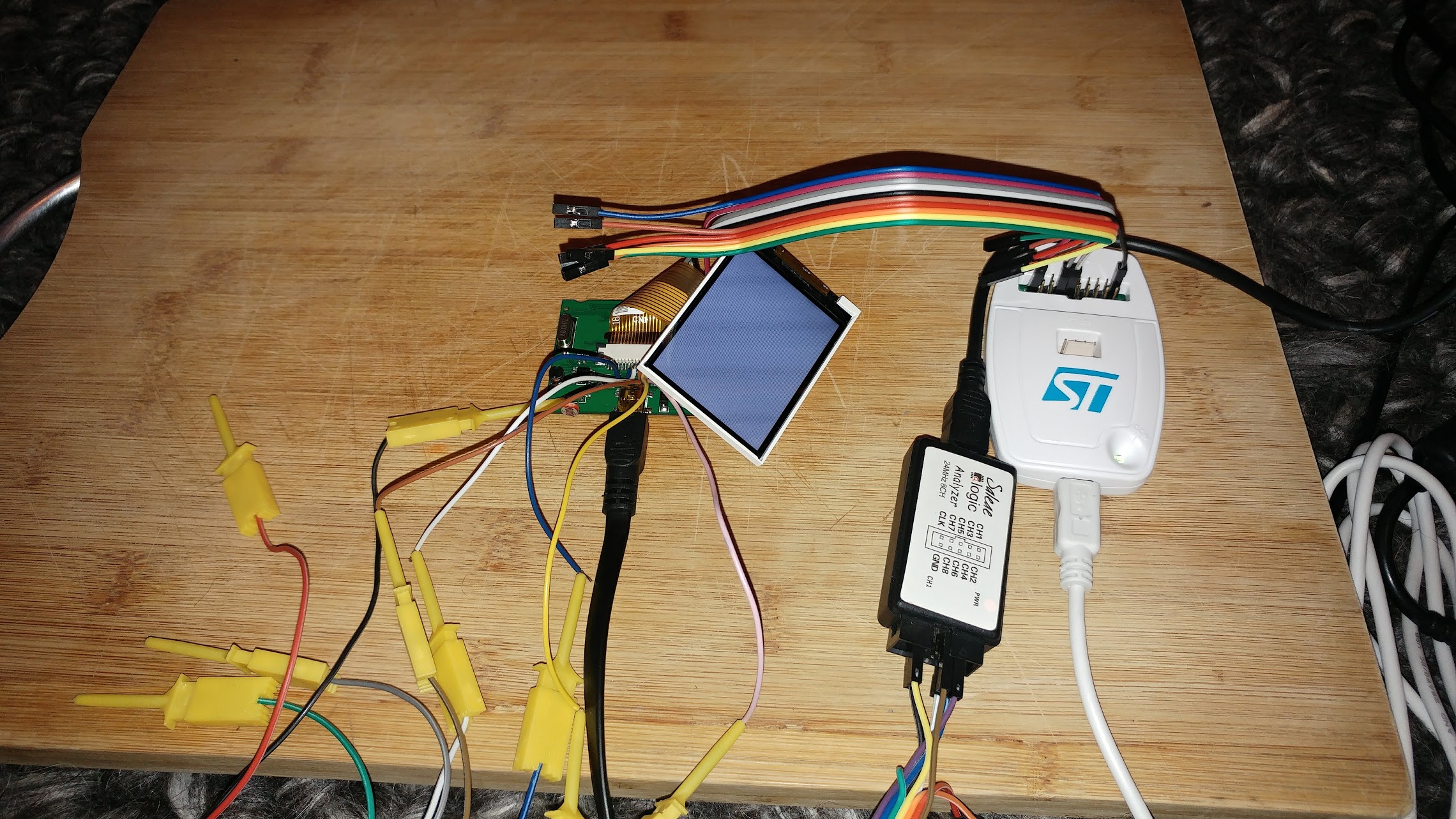
You can open this in Saleae Logic (free download from https://www.saleae.com/downloads )
http://www.internetsomething.com/autool … .logicdata
hmm. The scope shows an 18MHz clock though. That’s more believable.
tft.begin(mySPI2, 8000000); gives a 4.5MHz clock according to the scope, and 4MHz according to the L/A. It’s pretty dirty though.
I wonder, is there an issue with PA11 ?
I have just found out about the PA15 issue (it is wired for TFT_RST here), and since I’m using ST Link, I have set afio_cfg_debug_ports(AFIO_DEBUG_SW_ONLY);
That’s a good sign!
compare:
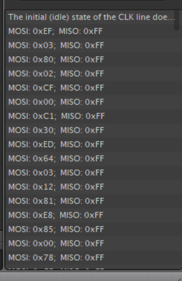
with: https://github.com/adafruit/Adafruit_IL … 1.cpp#L270
but I think D/C line is never changing
http://www.internetsomething.com/autool … .logicdata
[stevestrong – Mon Apr 16, 2018 9:01 pm] –
PA11/12 are USB pins.
In my case they are not wired as such. Is there some code that is switching them into USB mode that I can try to override?
The default for the chip is for PA11 to be PA11. Apparently USB is an alternate mode.
I have no USB port currently!
Take a look in boards.txt at the menu option for serial upload as it has the switches to disable USB Serial as it uses hardware Serial
[RogerClark – Mon Apr 16, 2018 9:07 pm] –
For STLINK uploads the USB is enabled by default in the coreTake a look in boards.txt at the menu option for serial upload as it has the switches to disable USB Serial as it uses hardware Serial
I’m tinkering with board.cpp and board.h as we speak, although I’m not really sure what I’m doing ![]() Commenting out USB assignments, increasing BOARD_NR_ADC_PINS, adding PA11 into the boardADCPins list. Still no worky
Commenting out USB assignments, increasing BOARD_NR_ADC_PINS, adding PA11 into the boardADCPins list. Still no worky ![]()
Oh. pa11 isn’t an adc pin anyway. i’ll try adding into into pwmpins
I think there is something like -DSERIAL_USB
In the upload menu option for STLink
Just remove that and save and then realised the IDE
[RogerClark – Mon Apr 16, 2018 9:16 pm] –
Change boards.txt not board.cppI think there is something like -DSERIAL_USB
In the upload menu option for STLink
Just remove that and save and then realised the IDE
You know I’m using PlatformIO as my IDE though right?
But I think it must retain some of those config somewhere otherwise nothing would work
You could try making sure that SERIAL_USB ( or perhaps it’s USB_SERIAL) is not defined as the core will use it as a flag to run all the USB Serial code
HOLY CRAP
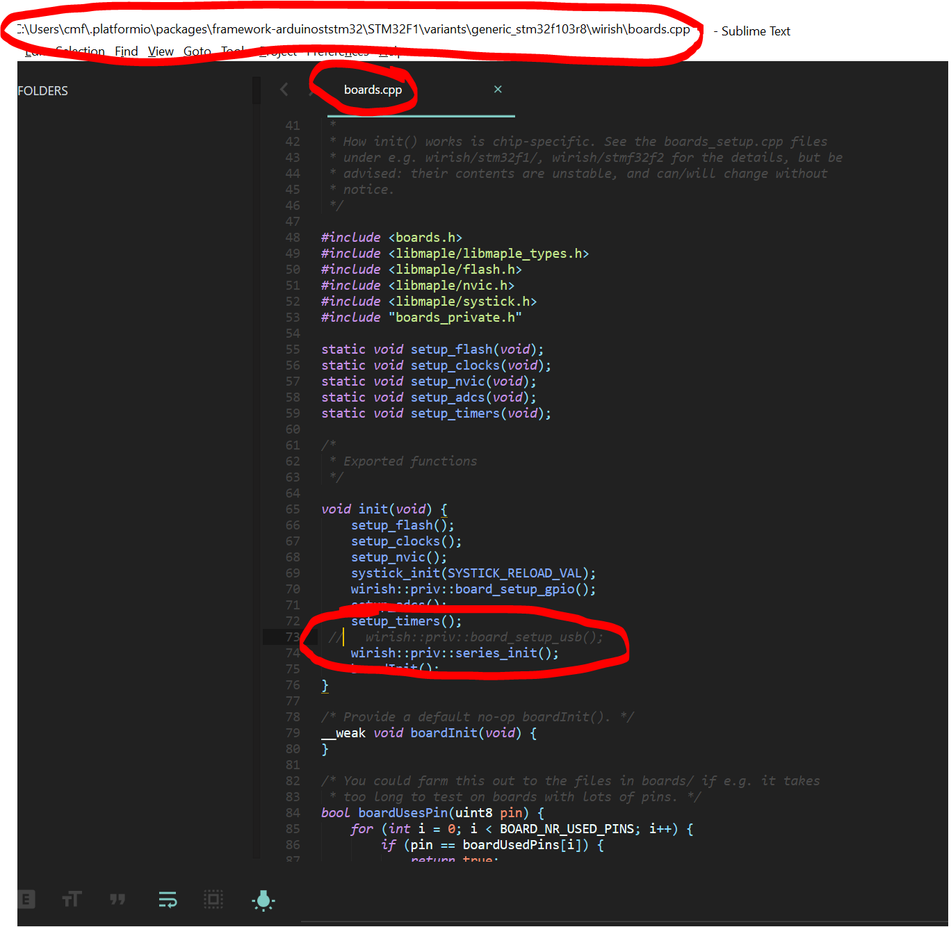
and now I have THIS ![]()
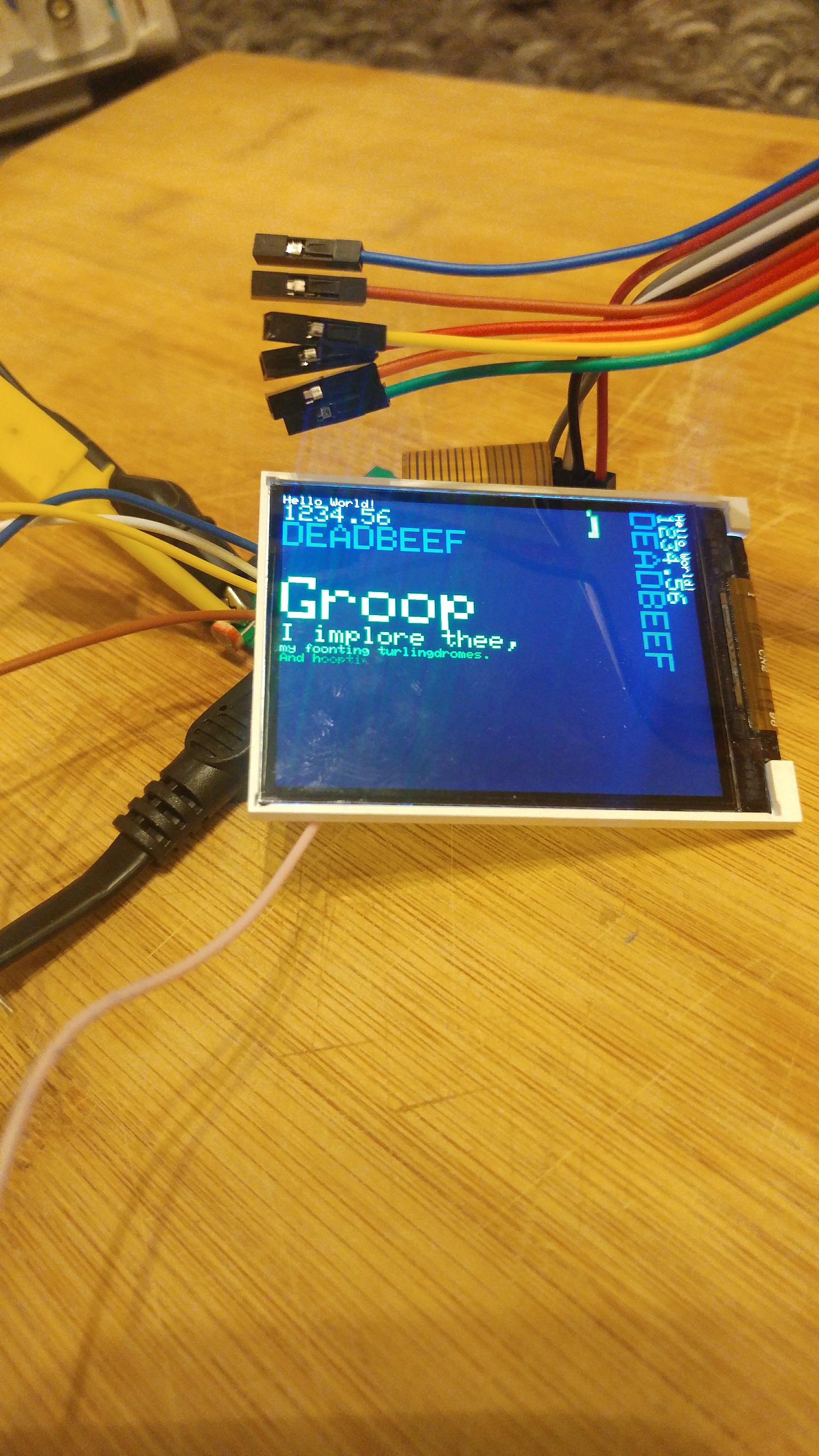
So the problems were simply RST pin being claimed by JTAG, and D/C pin being claimed by USB.
Also, I have had to switch the width and height in the ILI9341_STM file:
#define ILI9341_TFTWIDTH 320
#define ILI9341_TFTHEIGHT 240
BTW. The GD32 will run fine at 120Mhz and also with zero wait states in the flash, so you may want to change your settings as that would give you a considerable performance boost even over the 108Mhz it may be currently running at.
[RogerClark – Mon Apr 16, 2018 11:18 pm] –
CoolBTW. The GD32 will run fine at 120Mhz and also with zero wait states in the flash, so you may want to change your settings as that would give you a considerable performance boost even over the 108Mhz it may be currently running at.
Thanks Roger! Well, I am using genericSTM32F103R as a board definition.
I’m not sure how to override board settings in PlatformIO. I suspect your boards.txt might be pulled into in a database, or cached… it might be too late after I have created the project and chosen the board definition. Certainly I tried removing -DSERIAL_USB from the upload options but it didn’t work for my TFT problem. I’m still only able to get it working with the above change to the init function in boards.cpp.
Must say though, I’m rather chuffed that all of this is possible. When I ordered this thing I thought, hmmm.. I wonder if I’ll be able to use the screen. Someone on the arduino forums said it might just have a blob of epoxy over the chips, and here I am with a useable screen, microcontroller, and a couple of i/o things (I might use the CAN transceiver as my connection between this screen/controller and the separate datalogger device).
[RogerClark – Mon Apr 16, 2018 11:18 pm] –
CoolBTW. The GD32 will run fine at 120Mhz and also with zero wait states in the flash, so you may want to change your settings as that would give you a considerable performance boost even over the 108Mhz it may be currently running at.
I found it ![]() You have to put the options in platformio.ini within the project.
You have to put the options in platformio.ini within the project.
I could only choose 128MHz though. I got “error: ‘BOARD_RCC_PLLMUL’ was not declared in this scope” if I tried 120MHz.
The screen sure looks to be updating quickly with the CPU at 128MHz ![]()
Scope says the SPI clock is now 32MHz.
Incidentally, I was not able to get the SPI clock above 18MHz any other way. I tried setting the divider to DIV2, as well as specifying frequency in tft.begin, but I never got an SPI clock above 18MHz. It’s using a divider of 4 over CPU freq regardless.
I thought it was the GD32F103C8 which only has 64k flash (and it only has 64k shadow / program RAM)
https://github.com/rogerclarkmelbourne/ … 9e1aa8c15a
Change that to zero wait states, as only the STM32 need wait states
[RogerClark – Tue Apr 17, 2018 12:50 am] –
Ah OKI thought it was the GD32F103C8 which only has 64k flash (and it only has 64k shadow / program RAM)
Apparently not! ![]()
I just fixed the BGR / RGB colours now, so I’m happy. I might go to bed finally ![]()
I changed MADCTL_BGR to MADCTL_RGB in Adafruit_ILI9341_STM::setRotation(uint8_t m)
[RogerClark – Tue Apr 17, 2018 12:53 am] –
Seehttps://github.com/rogerclarkmelbourne/ … 9e1aa8c15a
Change that to zero wait states, as only the STM32 need wait states
Done ![]()
How will I know if it’s doing anything? The screen is spinning faster than I can see anyway, and I guess I’m limited by my 32MHz SPI clock for this?
Programs just run a bit faster i.e raw computation speed increases
[ahull – Tue Apr 17, 2018 3:24 am] –
![]()
I will trace out the CAN transceiver, and LM393 pins soon.
Given that PA11 and PA12 are labelled as CAN TX/RX on Maple, *but*, PA11 is used for LCD D/C on this board, I expect the CAN tranceiver will instead be wired to PD0 and PD1, as the datasheet says these are remap-able as such.
The LM393 will be going into a UART, for K/L Line serial-like data (iso 9141) which is good, because if I want a UART connection of some kind, I can change out that IC, or hookup in its place.
It doesn’t look like connecting to unused pins on the GD32 is going to be possible because the pitch is so fine on the LQFP64, so I must re-use what’s already broken out into other functions.
I suppose it would be good to have a look at the 2MB flash, check that I can read/write from it. Maybe get a bitmap on there and display it as a startup picture on the LCD.
There is a possibility that they have doubled up on pin PA11, since the display will ignore everything until it is selected, and they may be enabling the CAn transceiver only when it is needed, but your idea that they are using PD0 and PD1 sounds more likely. Which pins does the 2Mb flash use?
[ahull – Tue Apr 17, 2018 2:38 pm] –
Funnily enough I was going to remind you we hadn’t dumped the 2Mb Flash chip.There is a possibility that they have doubled up on pin PA11, since the display will ignore everything until it is selected, and they may be enabling the CAn transceiver only when it is needed, but your idea that they are using PD0 and PD1 sounds more likely. Which pins does the 2Mb flash use?
I’m not sure yet. I suppose it’s going to be i2c or SPI is it? It’s been a while since I had to read an eeprom chip. As I mentioned earlier, my SOFI SP8a failed to read it in-circuit. I do have a black magic probe on its way though, and I believe the other set of pin-headers on this PCB do go directly to that chip, so if I figure out what’s going on (something being held low or high or whatever), then I should be able to read it through those header pins, as I expect this is how it’s programmed at the factory. J2 header pins for SWD-debug to program the MCU, and J1 header pins to program the 2Mb (is it 2mbit or 2mbyte. I think it’s 2MB.. it says 25c16 or something, 16megabit).
I also realised I know nothing about using external flash with the Arduino. Clearly there’s no filesystem i.e. fat or anything. I guess you just store variables at address locations manually and read them back from there, and it’s mapped to the external flash. I’ll find some demo code to try out anyway.
I’ve not done the 3-way jog-button thing yet. That’s key, but easy !
I do have one big worry though. You know all along my plan is to use the other model of this thing – the Autool X60, which is in a gauge style rather than a pod style. Well, I am sure it is going to be very much the same inside, but I won’t know until it arrives from China as there were no UK sellers for it, but look.. that screen is clearly 1:1 square and not rectangle or 4:3. I’m worried that after all this effort to get the ST7789 LCD working, well, it will have a different TFT panel and driver chip after all :-/
See for yourself..
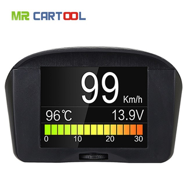
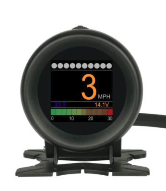
Also, this is obviously a brand new piece of kit, because the only YouTube video I could find for it, is from yesterday, and is in Russian:
Here is a sketch that should read it and dump it to the serial port. See this post if you want to know *why* I have been recently dumping 24C16 eeproms. -> http://stm32duino.com/viewtopic.php?f=45&t=3322
I suspect it will work without any modification other than to set up the correct serial port (it uses USB serial by default) and the correct pins for the eeprom.
// --------------------------------------

// Modified i2c_scanner to find, dump and update a SOR/T SOR/R  Dosimeter 24C16 EEPROM (and probably related devices).

// to hack in missing features.

//

// See http://stm32duino.com/viewtopic.php?f=45&t=3322

// for more about hacking these devices

// Latest code should be checked out with git sith something on the lones of...

//  git clone https://github.com/pingumacpenguin/SOR-T-SOR-R-Dosimeter-24C16-EEROM-dumper-and-updater..git

//

// The i2c scanner code came with the following comments.

// Version 1

//    This program (or code that looks like it)

//    can be found in many places.

//    For example on the Arduino.cc forum.

//    The original author is not know.

// Version 2, Juni 2012, Using Arduino 1.0.1

//     Adapted to be as simple as possible by Arduino.cc user Krodal

// Version 3, Feb 26  2013

//    V3 by louarnold

// Version 4, March 3, 2013, Using Arduino 1.0.3

//    by Arduino.cc user Krodal.

//    Changes by louarnold removed.

//    Scanning addresses changed from 0...127 to 1...119,

//    according to the i2c scanner by Nick Gammon

//    http://www.gammon.com.au/forum/?id=10896

// Version 5, March 28, 2013

//    As version 4, but address scans now to 127.

//    A sensor seems to use address 120.

//

//

// This sketch tests the standard 7-bit addresses

// Devices with higher bit address will not be seen properly.

//

// Additional i2c hints from http://playground.arduino.cc/Code/I2CEEPROM

//
// This code was written for and teseted on and STM32F103C8T6 - the so called BluePill - see http://wiki.stm32duino.com/index.php?title=Blue_Pill
// but should work pretty much unmodified on most 'duinos.
// Thanks to the many coding giants, who's shoulders this sketch stands upon.
//
// The hexdump of the 24c16 will appear as a set of C++ byte Arrayson the STM32 USB serial device, or UART1, depending on the settings in the IDE.
// See http://stm32duino.com for details of how the serial ports on the STM32F103XX devices are defined.
// For connection to the EEPROM, you should be able to use a SOC8 clamp to connect without the inconvenience of soldering to the board.
// WARNING: Do not leave the battery in the dosimeter and accidentally power it from the STLINK V2 or the USB port at the same time, the battery will pop.
// Search Ebay for "SOIC8 SOP8 Flash Chip IC Test Clips Socket Adpter BIOS" or similar.
// Include RTC for timestamps
#include "RTClock.h"
RTClock rt (RTCSEL_LSE); // initialise
uint32 tt;
// Define the Base address of the RTC registers (battery backed up CMOS Ram), so we can use them for config of touch screen and other calibration.
// See http://stm32duino.com/viewtopic.php?f=15&t=132&hilit=rtc&start=40 for a more details about the RTC NVRam
// 10x 16 bit registers are available on the STM32F103CXXX more on the higher density device.
#define BKP_REG_BASE (uint32_t *)(0x40006C00 +0x04)
// Time library - https://github.com/PaulStoffregen/Time
#include "Time.h"
#define TZ "BST"
#include <Wire.h>
// Somne sane ish defaults in case the RTC battery has been disconnected or run flat.
int thisYear = 2018;
int thisMonth = 3;
int thisDay = 28;
int lastDay = 0;
int thisHour = 12;
int thisMinute = 0;
int thisSecond = 0;
// Set to a recent value - Wed March 28 1028 22:43
#define RESET_TO_TIMESTAMP 1522273406
#define BLINK_PIN PC13 // Unused.. Can be used to assist with debugging.
#define BOARD_POWER PB9 // This can theoretically be used to power the 24c64 since the board draws a few miliamps.
// In the end, I just opted to power the board from 3v3 directly, as this makes life easier.
#define BOARD_WP PB8 // Pull down WP pin to allow us to write to the 24c64
void setup()
{
// Check time, and set a sensible time, if this board has no battery, or the time is unset
long int tt = rt.getTime();
// Check to see if we are close to the epoch, and if so, bad things must have happened to the RTC backup power domain.
if ( tt < RESET_TO_TIMESTAMP )
{
rt.setTime(RESET_TO_TIMESTAMP);
}
// Allow the USB to re-enumerate before we attempt to talk. You can probably shorten this delay considerably.
delay(15000);
// Using the BluePill, or other STM32F103XX boards, PB6 is SCL => Pin 6 on the 24C02
// PB7 is SDA => Pin 5 on the 24C02
// PB8 is GPOI used to pull WP (Write Protect) (Pin7) low on the 24C02 to allow writing to the chip.
// There is a pullup on WP on the Victor VC921 and probably most other devices, so we need to pull low to write.
//pinMode(PB6,OUTPUT_OPEN_DRAIN);
//pinMode(PB7,INPUT);
// Power up the multimeter if connected to the BOARD_POWER
//pinMode(BOARD_POWER, OUTPUT);
//digitalWrite(BOARD_POWER, HIGH);
//Enable writing to the eerom
//pinMode(BOARD_WP, OUTPUT);
//digitalWrite(BOARD_WP, LOW);
Serial.println("// SOR/T SOR/R Dosimeter 24C16 EEROM dumper and updater.");
//TwoWire Wire(PB6, PB7, SOFT_STANDARD);
Wire.begin();
Serial.println("// Waiting for Device to POST and i2c Bus to settle.");
delay(3000);
}
void loop()
{
byte error, address;
int nDevices;
serialCurrentTime();
Serial.println("//Scanning...");
nDevices = 0;
for (address = 1; address < 127; address++ )
{
// The i2c_scanner uses the return value of
// the Write.endTransmisstion to see if
// a device did acknowledge to the address.
Wire.beginTransmission(address);
error = Wire.endTransmission();
if (error == 0)
{
Serial.print("\n");
serialCurrentTime();
Serial.print("\n// I2C device found at address 0x");
if (address < 16) {
Serial.print("0");
}
Serial.print(address, HEX);
Serial.println(" ");
// Dump the current rom values, so we have somthing to fall back on if it all goes pear shaped.
// NOTE: The 24c16 also contains calibration values, so should be unique to the dosimeter, simply pasting the hexdump from
// one dosimeter to another will almost certainly screw up the calibration.
dump24c02(address);
// delay(1000);
nDevices++;
}
else if (error == 4)
{
Serial.print("//Unknow error at address 0x");
if (address < 16)
Serial.print("0");
Serial.println(address, HEX);
}
}
if (nDevices == 0)
Serial.println("//No I2C devices found\n");
else
Serial.println("\n//Done.\n");
// Put any changes to bytes immediately after the dump, since that will ensure they hit the found i2c device.
delay(60000); // Wait n seconds then re-scan.
}
void dump24c02(byte i2cAddress)
{
int hexDumpWidth = 0x10;
int addrPointer = 0;
//int romLength = 0xff; // 24c02 - 256x8 bits (256 bytes)
int romLength = 0xff; // 24c04 - 512x8 bits (512 bytes)
byte b = 0;
// Spit out each 256 byte page of the eeprom contents as a byte array
Serial.print("static const byte eeprom");
Serial.print(i2cAddress, HEX);
Serial.println("[][0x10] =");
Serial.println("{");
while (addrPointer <= romLength)
{
if ((addrPointer % hexDumpWidth) == 0 ) {
if (addrPointer == 0) {
Serial.print(" {");
} else {
Serial.print("} //0x0");
Serial.println(addrPointer, HEX);
Serial.print(",{");
}
} else {
Serial.print(",");
}
b = i2c_eeprom_read_byte(i2cAddress, addrPointer); // Read byte
addrPointer++; // increment address pointer
Serial.print("0x");
if (b < 0x10) {
Serial.print("0");
}
Serial.print(b, HEX); // Print byte
//Serial.print(",");
}
Serial.print("} //End of page 0x");
// Serial.print("// ");
Serial.print((i2cAddress - 0x50), HEX);
Serial.println();
if (!(addrPointer % hexDumpWidth)) {
Serial.println("};");
} else {
Serial.println("");
}
}
byte i2c_eeprom_read_byte( int deviceaddress, int eeaddress ) {
//Wire.beginTransmission(deviceaddress & ((eeaddress & (int)0x100 ) >> 9));
Wire.beginTransmission(deviceaddress);
Wire.write((int)(eeaddress & 0xff));
// Wire.write(address & 0xFF);
//Wire.write((int)(eeaddress >> 8)); // MSB
//Wire.write((int)(eeaddress & 0xFF)); // LSB
Wire.endTransmission();
Wire.requestFrom(deviceaddress, 1);
if (Wire.available()) {
return Wire.read();
} else {
return 0xff;
}
}
void i2c_eeprom_write_byte( int deviceaddress, int eeaddress, byte data ) {
digitalWrite(BOARD_WP, LOW);
delay(100);
int rdata = data;
Wire.beginTransmission(deviceaddress);
Wire.write((int)(eeaddress)); //
Wire.write(rdata);
Wire.endTransmission();
//digitalWrite(BOARD_WP, HIGH);
}
void serialCurrentTime() {
long int tt = rt.getTime();
Serial.print("// Current time - ");
if (hour(tt) < 10) {
Serial.print("0");
}
Serial.print(hour(tt));
Serial.print(":");
if (minute(tt) < 10) {
Serial.print("0");
}
Serial.print(minute(tt));
Serial.print(":");
if (second(tt) < 10) {
Serial.print("0");
}
Serial.print(second(tt));
Serial.print(" ");
Serial.print(day(tt));
Serial.print("/");
Serial.print(month(tt));
Serial.print("/");
Serial.print(year(tt));
Serial.println("("TZ")");
}
Well, the thing is, a blog post elsewhere on the Internet showed the v4.3 of this PCB with everything identical except the flash part being a Spansion S25FL216KIF which is 16MBit.
However my board (v4.4) has a part labelled C25Q16SN (or it might be C25016SN). I can’t find info on that p/n.
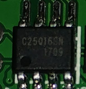
This topic might be useful -> viewtopic.php?t=1787
As you can see, my part is physically smaller, but is soldered to the same pads (hence the large silver pcb tracks showing next to the IC legs), and also the white line shows that a wider chip was originally supposed to be fitted there, like in the other person’s photo.
My part:
Other person’s part:
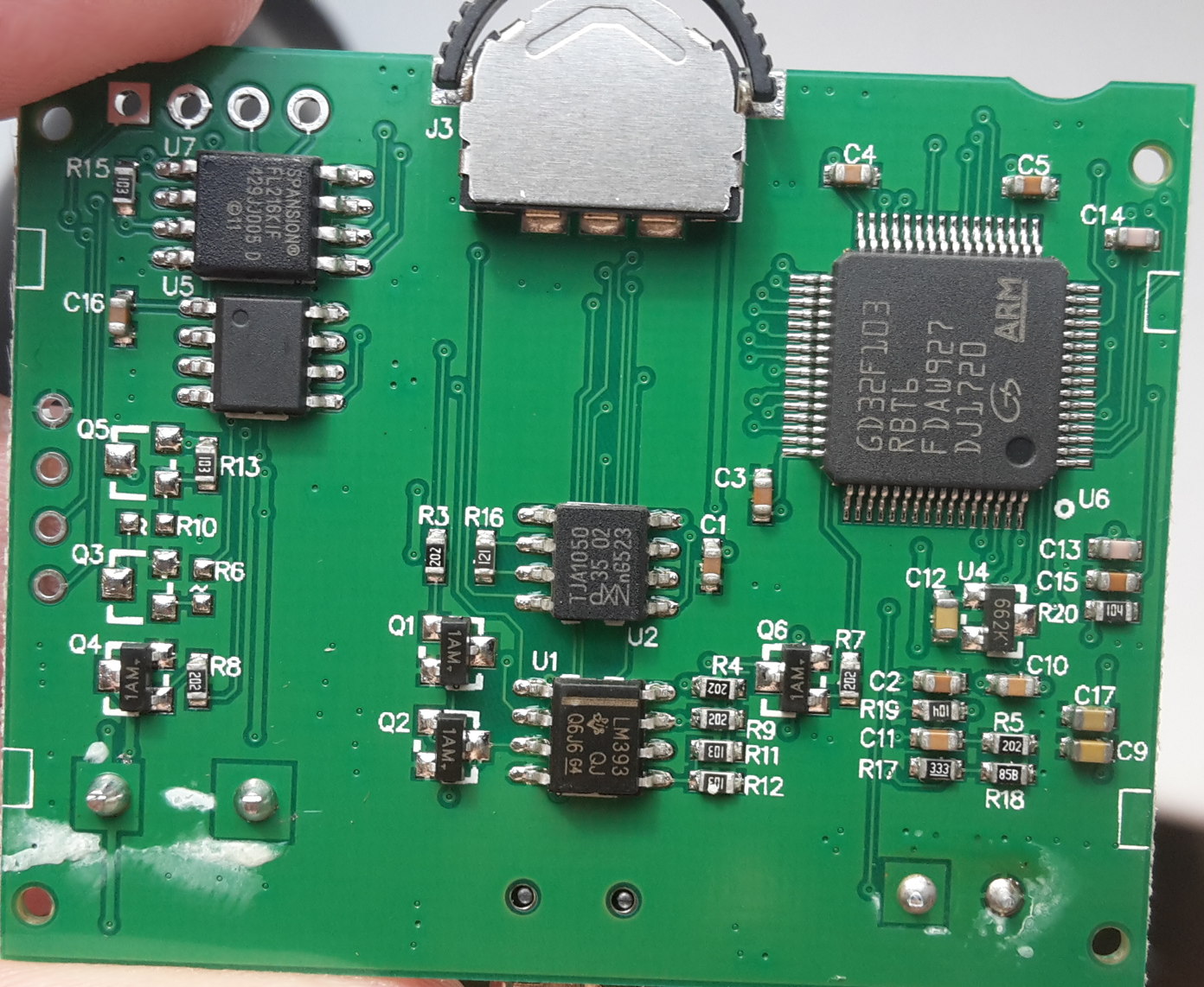
You would think that the parts are pin-compatible.. maybe. Unless they use different software settings. Mine is more like the size of an i2c eeprom or something isn’t it. Whereas the other Spansion part looks wide like flash memory.
[ahull – Wed Apr 18, 2018 11:24 am] –
Looks like this beast here.-> https://www.qdatasheet.com/pdf/Spansion/185048.pdf
I wonder if my physically smaller part is compatible though?
[carl0s – Wed Apr 18, 2018 11:45 am] –[ahull – Wed Apr 18, 2018 11:24 am] –
Looks like this beast here.-> https://www.qdatasheet.com/pdf/Spansion/185048.pdfI wonder if my physically smaller part is compatible though?
Yes, I suspect it is.
The device comes in two different packages, if you look at the end of the datasheet you will see it is available as both …
8-Pin SOIC 150-mil Package (SOA 008) ( approx 6mm between opposite pads)
and
8-Pin SOIC 208-mil Package (SOC 008) (approx 8mm between opposite pads)
Exact dimensions are in the datasheet.
The problem is that your clip on adapter might have trouble grasping the smaller part. You should still be able to read the data directly with the GD32 obviously.
[ahull – Wed Apr 18, 2018 12:15 pm] –[carl0s – Wed Apr 18, 2018 11:45 am] –[ahull – Wed Apr 18, 2018 11:24 am] –
Looks like this beast here.-> https://www.qdatasheet.com/pdf/Spansion/185048.pdfI wonder if my physically smaller part is compatible though?
Yes, I suspect it is.
The device comes in two different packages, if you look at the end of the datasheet you will see it is available as both …
8-Pin SOIC 150-mil Package (SOA 008) ( approx 6mm between opposite pads)
and
8-Pin SOIC 208-mil Package (SOC 008) (approx 8mm between opposite pads)
Exact dimensions are in the datasheet.
The problem is that your clip on adapter might have trouble grasping the smaller part. You should still be able to read the data directly with the GD32 obviously.
Thanks Andy. I should be able to have a look at this tonight!
[carl0s – Thu Apr 19, 2018 11:07 am] –[ahull – Wed Apr 18, 2018 12:15 pm] –[carl0s – Wed Apr 18, 2018 11:45 am] –I wonder if my physically smaller part is compatible though?
Yes, I suspect it is.
The device comes in two different packages, if you look at the end of the datasheet you will see it is available as both …
8-Pin SOIC 150-mil Package (SOA 008) ( approx 6mm between opposite pads)
and
8-Pin SOIC 208-mil Package (SOC 008) (approx 8mm between opposite pads)
Exact dimensions are in the datasheet.
The problem is that your clip on adapter might have trouble grasping the smaller part. You should still be able to read the data directly with the GD32 obviously.Thanks Andy. I should be able to have a look at this tonight!
Just trying again with my SP8a to read the SPI flash. You’re right that the clamp thing is no good, but (according to the foreign blog post), the SPI pins are broken out onto J1 of the PCB.
J1 header on the PCB doesn’t go to the flash at all.
J1 is a 4 pin header (well, it is after you solder headers in there..)
Pin1 = GND
Pin2 = Nothing (it would go to collector of missing transistor Q5. I’m going to trace out where the B/E might lead to if one was fitted.)
Pin3 = PB10
Pin4 = PB11
This means PB10 and PB11 are broken out onto header J1!
These are I2C-2 clock and data, or USART3 TX and RX. They can be remapped to TM2 CH3 and CH4.
So it means we have a UART available for use right away on the board without having to remove the K/L line transceiver chip (LM393) or try to solder wires to MCU legs or anything. That’s great news.
Regarding the SPI flash:
Pin 1 (CS) goes to PB0
Pin 2 (MISO) goes to PA6
Pin 3 (WP) shows as going to VDD so is high. Not sure of the implications of this without reading the datasheet properly. Have only looked at pinouts so far.
Pin 4 is GND
Pin 5 (MOSI) goes to PA7
Pin 6 (SCLK) goes to PA5
Pin 7 (HOLD) goes to VDD. Again not sure what this does.
Pin 8 is VCC.
So it is connected to SPI1 as per the GD32 datasheet. Should be all good!
I think my next move will be to connect to UART3 and get something on my terminal, maybe display stuff on the LCD that I type.
J2
1 (left) – SWDIO
2 – SWDCLK
3 – GND
4 (right)- VDD
Board needs external power to use STLink though. VDD should just be connected to ‘target vcc detection’ pin of STLink (pin #1)
J1
1 (top) – GND
2 – nothing
3 – PB10
4 (bottom) – PB11
With the board still in the same orientation, 3 way switch / jog thingy pinouts:
Rotate Left: PC14
Push Middle: PC15
Rotate Right: PC13
Serial will make code debugging so much easier. ![]()
I wonder if there is anything interesting coming from the serial pins of the untouched device.
[ahull – Fri Apr 20, 2018 8:00 am] –
Neat. That just leaves the flash to decode and the ODB II interface to de-cypher. Pretty good progress in a few days considering we started knowing nothing about the thing.Serial will make code debugging so much easier.
I wonder if there is anything interesting coming from the serial pins of the untouched device.
Yep ![]()
I was wondering the same about the original device. Unfortunately I returned it (the one I ordered after I accidentally erased this one) to Amazon after very carefully checking whether I could dump its software (I couldn’t because read-out protection was enabled).
When the X60 round-version comes, I’ll be sure to check.
Do we know which pins on it go where?
[ahull – Fri Apr 20, 2018 2:52 pm] –
BTW did we figure anything out about the “mystery” chip, I think it was U5, the one with no writing on it?Do we know which pins on it go where?
That’s right, U5. No I haven’t looked at it yet.
My Black Magic Probe arrived today. I don’t know what to do with it, other than use it instead of my ST Link V2, and instead of the USB to TTL converter. I think it does both of those in one.
I still need to watch that Hackaday video on debugging that Rick posted.
[Rick Kimball – Sun Apr 15, 2018 6:05 pm] –[carl0s – Sun Apr 15, 2018 1:51 pm] –
I was about to try some code to vary the screen brightness based on the LDR, but, without a serial console, I don’t know what numbers are coming back from analogRead(LDR_PIN), so I don’t know what maths to do for the analogWrite to the TFT_LED.Am I approaching this properly? Should I come back to it once I have a serial console?
You could use your stlink programmer as a debugger and look at the values in arm-none-eabi-gdb … Al from Hackaday did a nice video describing how to do basic debugging.
Damn that’s awesome. I just need to try to do that with my BMP, and also see how PlatformIO integrates it. A job for tomorrow’s rainy day.
Thanks for posting it.
I don’t think the pinouts match any kind of i2c eeprom, nor do the MCU pins match up with any clues on the GD32 datasheet.
It goes like this:
1-VCC    GND-8

2-          -7

3-       PC8-6

4-PC7    PC9-5
The 120 ohm end-of-line CAN resistor is present across IC pins 6 and 7 (CAN High and CAN Low). This is R16. For some projects where you are sniffing an existing bus, I think you would want to remove this resistor.
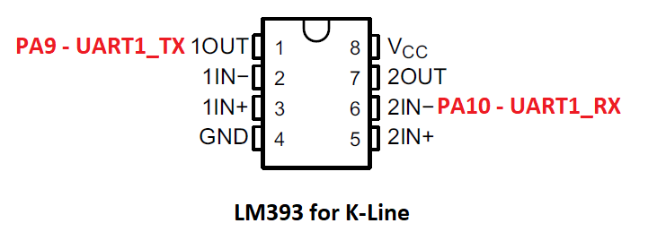
I have to admit, I don’t understand how this thing works.
On my own project, I used an ST L9637D for UART <-> K-Line.
Regardless, you could just configure UART1 to 10400 bps and away you go.
I spent a lot of time scratching my head when it didn’t work because I had #include SPI.h before #include SPIFlash.h
It only works if you #include SPIFlash.h before SPI.h
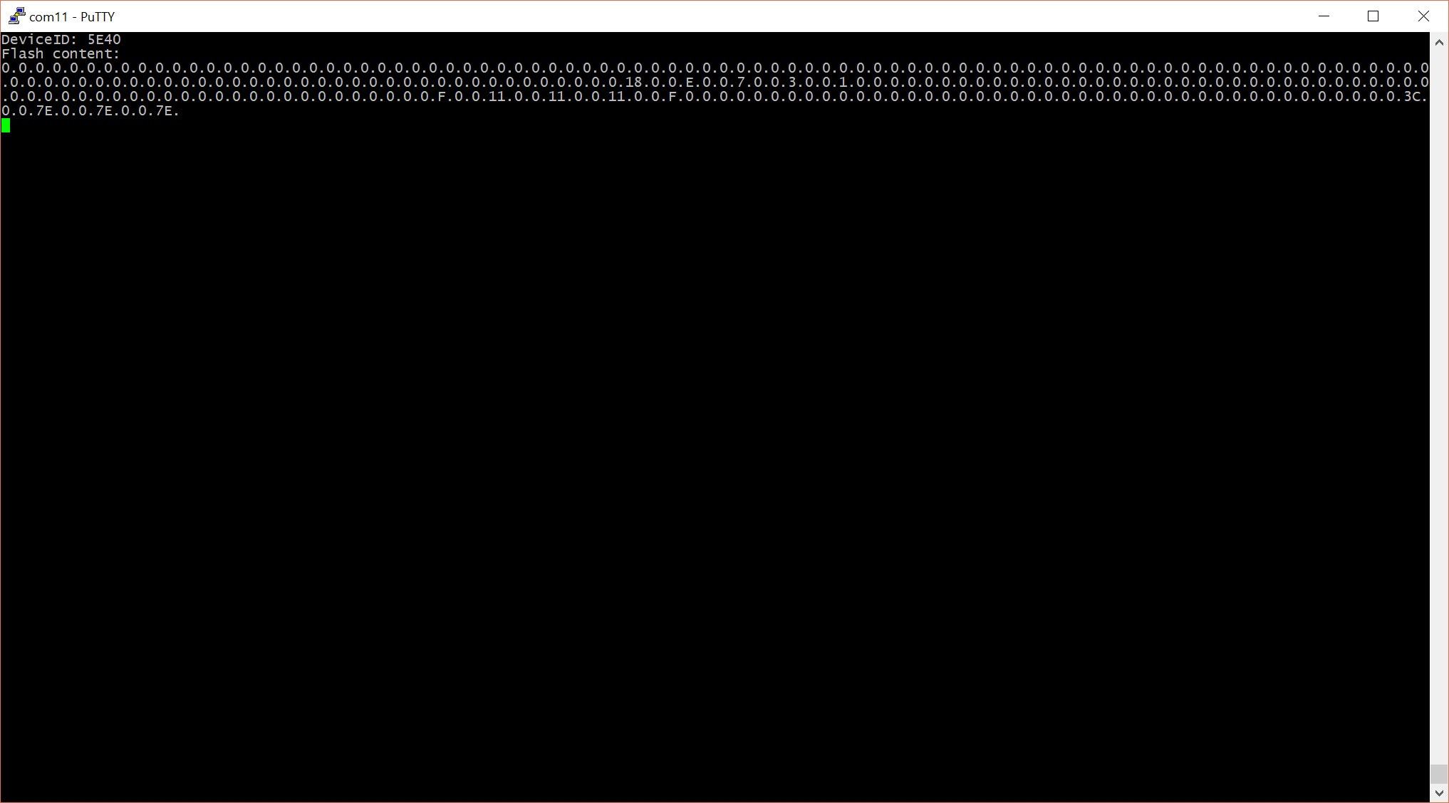
I’m going to try it with Paul S (teensy)’s SerialFlash library.
Have you seen this UI ? I want it! It’s all written around UTFT though.
I was finally able to read it in-circuit with the SOFI SP8a, by choosing Device Type: Winbond W25X16V [ISP]. You have to choose a chip definition that says [ISP] otherwise it insists on something being put in the ZIF socket. There were no Spansion chip definitions that said [ISP] so I went with a 16mbit Winbond of the 25x series that I read was supported by the same Arduino SPIFlash library that I already found to work with the chip, and that I’d verified commands match the Spansion data sheet.
I made sure the board was already running, but not with anything that was using SPI1, so that the ISP didn’t end up trying to power the MCU and everything else.
You can see lots of car diagnostics related strings in the dump. I expect it’s just a list of codes and their descriptions. I should try binwalk on it though.
Here’s the file: http://www.internetsomething.com/autool … 16mbit.bin
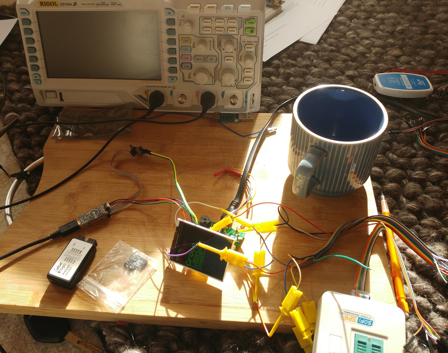
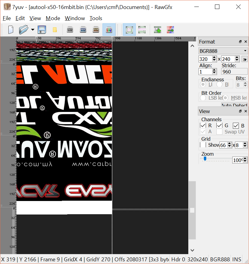
bit of messing around in MS Paint…

[carl0s – Sun Apr 22, 2018 12:42 pm] –
OK the mystery chip is still a mystery.I don’t think the pinouts match any kind of i2c eeprom, nor do the MCU pins match up with any clues on the GD32 datasheet.
It goes like this:
1-VCC    GND-8

2-          -7

3-       PC8-6

4-PC7    PC9-5
[RogerClark – Sun Apr 22, 2018 10:15 pm] –[carl0s – Sun Apr 22, 2018 12:42 pm] –
OK the mystery chip is still a mystery.I don’t think the pinouts match any kind of i2c eeprom, nor do the MCU pins match up with any clues on the GD32 datasheet.
It goes like this:
1-VCC    GND-8

2-          -7

3-       PC8-6

4-PC7    PC9-5
[RogerClark – Sun Apr 22, 2018 10:20 pm] – PC7 ???
Sorry I hit Submit by accident before finishing ![]()
[ahull – Mon Apr 23, 2018 4:24 am] –
Those graphics suggest this device is a close relative too -> http://carpro.com.my/shop/index.php/eas … splay.html
Yup ![]()
I didn’t get much further than you, but I suspect there is more graphical “stuff” in that flash chip image.
These are some of the “images” I extracted using convert ….
convert -depth 8 -size 320x240 bgr:autool-x50-16mbit.bin -roll +240+32 out2.png
Because although the number of pixels per line if the same for all parts of that image, the start address of the next part of the image is not directly after the end address of the previous image.
I would suggest perhaps there is a small header befor each image but I can’t see any evidence of that in the photos , but perhaps I just can’t see it
There used to be a thing called Action Replay on the Amiga. It was like a hardware debugger that could cut-in to anything that was running on the system. Really cool. You could browse through RAM and find images, as well as bookmark numbers and see if they changed (when your score changed in a game for example.. to locate where score was stored in ram, and modify), and save the running state of the machine, etc.
Anyway that’s what I was thinking of when I found that 7yuv tool that let me scan through the .bin/.hex in a visual way. I wonder if there are other/better tools? That one was ok. clunky interface, and didn’t cope with my HiDPI screen. I think I might be able to overcome the DPI issue though, as I have been playing with per-app-DPI settings in preparation for the gadget that I ordered last night: DSLogic Plus (the one with the bigger 256MByte on-board buffer). 16 channels of hopefully actually usable logic analyzer for 86 quid. God I wish I was single.
[RogerClark – Tue Apr 24, 2018 1:39 am] –
HxD is a good general purpose hex editor, but it doesn’t view images etc
Yes I do have that installed but I was specifically looking for something to visualise. That 7yuv program worked just fine. At first I could see the image but colours were weird, so I changed colour format. Would have been nice to be able to alter the start/end, kind of like width/margins. When browsing car ECU dumps with WinOLS (for finding maps) you can do all that stuff (fix the widths and start/end to size/shape things properly), and it visualises things for you so you can find tables of map data. That’s an expensive program though for what it does.
Over on the AVR freaks forums I was able to use Ghostscript to decode the encoded numerical states of of a mixed Graphics/Segment display from a Yamaha PSR 620. https://www.avrfreaks.net/forum/yamaha- … d-lcd-dead That was much more difficult as I only had some screen shots in that thread to work with.
I have not had the time to look at this binary to see if there is anything interesting in the dump of this OBD device. Am still attempting to find the time to try the cheap (as in free) non standard TFT display I got from the tradeshows years ago on the STM32.
Edit: I opened the bin in a hex editor and there are quite a few text strings in it. This is where Postscript comes in handy as it can separate text from binary. Looking at the dump it does not look too unlike other things I have dumped such as the Mars Mairner9 data tapes. Often in tables like these there are pointer offsets into other areas of the code/data. As there is alignment in the logo graphics these would be easy to process. The text tables could then be dumped to see if they are in a linked list or an array of fixed length or zero terminated stings. Note that Pascal style strings with a length byte are a form of linked list.
strings autool-x50-16mbit.bin |grep "^P[0-9][0-9][0-9][0-9]" >PXXXX_Codes.txt
@carl0s Does the device offer more than one language option?
I notice that at address 0x13F45F the sequence starts with 0x20 which is a space and the text field ends with a space. The data the follows has high bits set. The next space is at 0x13F480, then there is a <CR><LF> and a space. <CR><LF> is often and end of line or end of sequence. The rest of the P codes seem to be preceded by <CR><LF>. The first one at 0x13F45F is not, so this likely represents the end of the record.
When we get down to 0x14D3B3 the strings do not seem to contain the high bits set. This pattern seems to end at 0x159402 with an eol. It has been 20 years since I worked with non roman graphics. So I would have to re read the chapters on such.
One of the other projects I am working with, is terminal emulation with box drawing characters. Such was used in older MIDI gear for showing value settings. As I am not a motor gear head, I do not know if this sort of things is done. I do know that when I drive my parents Prius that it is like booting up a computer to start and it has all kinds of bar graphs. My own Honda has a lot more on the display than the clock or a backup camera.
I am sort of wondering if such things could use say a java interface. ST makes a really expensive Java development kit for the STM32. I got as far as downloading the Games demo. The MIDI organ emulator is written in java (Why it is called jOrgan) Just blue skying here as it is easy to create graphic widgets Java. Something that could be tested/emulated on a cheap platform.
On the other hand there are libraries such as the STemWin one that The ST reps push with effort in the trade seminars. That might be the more likely API this data plays into.
I think this piqued my weakness for parsing data. Perhaps I will write a script to distill some of this data…
Edit: I did some online reverse image search, looking for the owners manual. It looks like some of this text is menu screens, like the Yamaha PSR MIDI keyboard. I found one You tube video that showed a language section option menu item. This only showed EN. The website in the links indicate that the price is in Malaysian currency. TinEye and Google find similar displays and others looking for owners/user manual links.
These things are pretty cheap I guess they sell high volume enough to handle the injection molds and some decent graphics designers. Interesting to contrast to the MIDI gear which is in simple steel boxes, and valued and priced, by weight and the number of knobs and blinkelights.
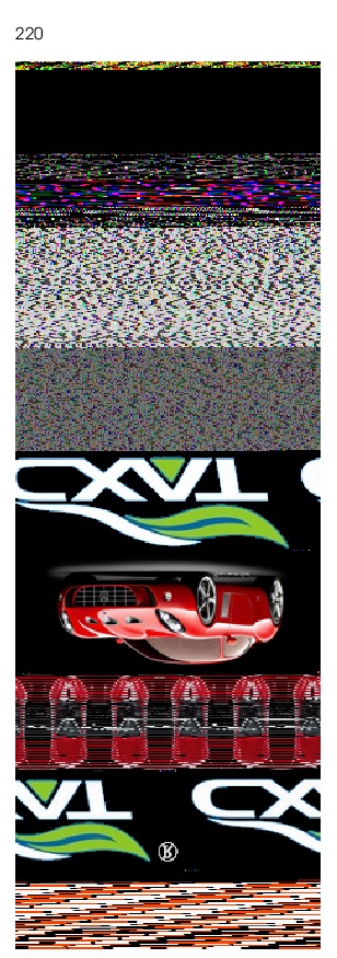
- cobd18424.jpg (145.59 KiB) Viewed 229 times
For example …
grep --text --color='auto' -P -n "[\x80-\xFF]" autool-x50-16mbit.bin |grep -a "P[0-9][0-9][0-9]"
[ahull – Wed Apr 25, 2018 3:23 am] –
@Sheepdoll it is possible to grep for say utf8 with some clever trickery.
…
Its also possible that characters with the high bit set, simply map to characters above 128 in the font that we assume is in the flash dump, so in other words, we may need to decode the font before we can make sense of these strings.
From what I was able to find in online documentation the languages are English French and Spanish.
In looking at the big picture with postscript I have not been able to find any graphics in the front of the file. It looks like font or icon, but I can not find any color space that makes sense. The repeat is 72 bytes 8 bit pixel gray scale this is the pattern:
- cobd1824B.jpg (47.52 KiB) Viewed 162 times
convert -depth 1 -size 320x240 gray:autool-x50-16mbit.bin -roll +240+32 out2.png
- cobd18425A.jpg (26.98 KiB) Viewed 157 times
convert -depth 1 -size 160x240 gray:autool-x50-16mbit.bin -roll +240+32 out2.png
convert -depth 1 -size 8x480 gray:autool-x50-16mbit.bin out2.png
convert -depth 1 -size 8x72 gray:autool-x50-16mbit.bin out2.png
I suppose it would be good to get an image in hex, i.e. with a clear start, end and format specification, then it might be possible to replace the image with your own choice of logo. I wonder if they are stored as simply as bitmap arrays, or if they are files in some kind of filesystem?
I’ve come to a bit of a standstill on the project for now because, basically, I’ve got what I wanted – the hardware is open! I suppose I could do a proper job of documenting it – proper diagrams.
I need to see if the round version (X60) can be used the same – has the same display controller etc, so I will be repeating with that when it finally arrives, but, apart from that, I now have a big project of learning how to do a nice GUI menu system from scratch. If only there were more hours in the day.
I grabbed the first 256 bytes of that flash dump.
dd if=autool-x50-16mbit.bin of=chunk.bin bs=256 count=1
[carl0s – Wed Apr 25, 2018 8:26 am] –
Interesting work
… its keeping me entertained ![]()
I suppose it would be good to get an image in hex, i.e. with a clear start, end and format specification, then it might be possible to replace the image with your own choice of logo. I wonder if they are stored as simply as bitmap arrays, or if they are files in some kind of filesystem?
Re-using the existing fonts in your own project, and replacing the existing images should be fairly easy. There doesn’t appear to be any file system. As you can see from my previous post, the first font appears to start at the start of the flash file. There may be some pointers hidden in the dump somewhere, pointing to each of the chunks of data but I suspect the pointers are (were) in the firmware.
I’ve come to a bit of a standstill on the project for now because, basically, I’ve got what I wanted – the hardware is open! I suppose I could do a proper job of documenting it – proper diagrams.
I need to see if the round version (X60) can be used the same – has the same display controller etc, so I will be repeating with that when it finally arrives, but, apart from that, I now have a big project of learning how to do a nice GUI menu system from scratch. If only there were more hours in the day.
There may be some existing Arduino gui libraries that you can re-purpose. You also have the luxury of lots of flash to put stuff in, so you should be able to make a pretty professional job of it. ![]() There is nothing to say you need to keep any of the existing fonts or images, since we now have a dump of them.
There is nothing to say you need to keep any of the existing fonts or images, since we now have a dump of them.
[ahull – Wed Apr 25, 2018 9:11 am] –
There may be some existing Arduino gui libraries that you can re-purpose. You also have the luxury of lots of flash to put stuff in, so you should be able to make a pretty professional job of it.
Yeah I want to do it like this: https://forums.adafruit.com/viewtopic.php?f=19&t=134574
I’ll make a start on it one day soon..
Since you have a big chunk of flash there to play with, you should be able to produce something a bit more professional.
This should probably go in a separate topic, but does anybody know of a good looking menu system for Arduino?
Here is the first few languages starting at byte 0 plotted on a 25×25 grid. I decided to leave the mask inverted, The white background pixels in between each mask is not part of the file. These were drawn with the postscript ‘Imagemask’ operator, with interpolation true. part of the Type3 (bitmap) font machinery.
- cobd18424C.jpg (117.96 KiB) Viewed 263 times
The postscript code to dump the fonts is about 200 or so lines. If there is interest I can post it to my git or upload it here (probably in a separate thread.)
Yes, i would be interested to see how that works.
When I get time I’m going to split an move this thread
it started as a new user post, but seems to about a “car computer” so it would be better if I (somehow) split the initial few posts from the rest of the the thread and make a new topic called something like GD32 Car Computer
[RogerClark – Thu Apr 26, 2018 4:00 am] –
GuysWhen I get time I’m going to split an move this thread
it started as a new user post, but seems to about a “car computer” so it would be better if I (somehow) split the initial few posts from the rest of the the thread and make a new topic called something like GD32 Car Computer
Good move, maybe “Hacking the GD32 based ‘Autool X50 OBD2 Monitor and diagnostic Display’ (and close relatives)”
That should contain enough keywords to cover the topic I think.
I’ll backup the DB now and then try that !
Look at the thread, I’m going to move the whole lot and change the title as the first post has loads of formation and photos
Edit. Whole topic moved to Projects
Note. I can’t do a batch change the titles of the replies, so I’ve just changed a few of them manually e.g. the posts at the start of this thread and the ones on this page
I wonder since that display worked with the GD32, perhaps some recent changes to the SPI or ILI9341 libs now would allow my GD32 boards to work with an ILI9341 display
When I get some time I will wire one up and see if it works
[ahull – Thu Apr 26, 2018 3:55 am] –
Excellent workThe postscript code to dump the fonts is about 200 or so lines. If there is interest I can post it to my git or upload it here (probably in a separate thread.)
Yes, i would be interested to see how that works.
It is pretty late now So I will probably clean up the code and post it tomorrow. I have identified all the offsets to the fonts. There are quite a few the whole first part of the flash. First there is the page I uploaded then there is one more of box draw. Some blank space then 10 pages of Chinese fonts.
Then this whole sequence repeats in bold face (thicker lines.)
After that things get messy. These are the standard fonts Roman sans serif in progressively larger sizes.
The part I am currently working on is the 10 large numbers. This is the only part where there is data 0x78 between each glyph. There is also a large minus sign, which does not align.
After the 10 digits are the icons. Then the text starts. I am currently working on the icons. Having trouble finding the start byte do to the unlined section after the 10 digits. It looks like they are 32 bits across, they may differ in height. (it is after midnight so I am going to call it a day.)
Actually it does manage to extract a large number of the glyphs as individual .png files
If anybody wants to try this for themselves, the magic incantation is…
convert -depth 1 -size 24x24 gray:autool-x50-16mbit.bin out2.png
Doing a lot of decomposing data file structures, wondering if it might be of use/interest.
There are binaries for all platforms and i seem to recall it being unlimited, maybe a little upgrade nagging
i got my own copy as i was using it at/for work, work istr bought a copy as well.
stephen
[RogerClark – Thu Apr 26, 2018 4:45 am] –
BTW.I wonder since that display worked with the GD32, perhaps some recent changes to the SPI or ILI9341 libs now would allow my GD32 boards to work with an ILI9341 display
When I get some time I will wire one up and see if it works
I don’t know if this is normal, and remember I was on SPI2, with: SPIClass mySPI(2);
BTW here is a bit of font fun… the first 1410 glyphs from the fonts.
I would include all 29128 of them in a single GIF, but there is a size limit on the files I can upload here, so I skipped all the Chinese ones and the later fonts.
convert -delay 10 -loop 0 out2-{1..1410}.png Fonts.gif
[ahull – Thu Apr 26, 2018 12:44 pm] –
That might be a bug, but I will defer to the experts.BTW here is a bit of font fun… the first 1410 glyphs from the fonts.
I would include all 29128 of them in a single GIF, but there is a size limit on the files I can upload here, so I skipped all the Chinese ones and the later fonts.
Fonts.gif
There is something slightly mesmerising about watching them all flash past.
LOL you guys are crazy ![]() Yes it is mesmerising!
Yes it is mesmerising!
Box drawing characters, full colour and reverse video. Sounds like a trip back to the 1980s
I’m sure there is space in that flash for a full PETSCII character set.
We already have a 6502 Commodore emulator. -> viewtopic.php?f=19&t=433
Now you can go the whole hog and emulate all the extended character ROMs too.


I’ve put both font glyph gifs on Google Images, they may or may not be visible above.
Google Images is a little quirky that way.
Inverse video anybody?

- Fonts3.gif (76.79 KiB) Viewed 530 times
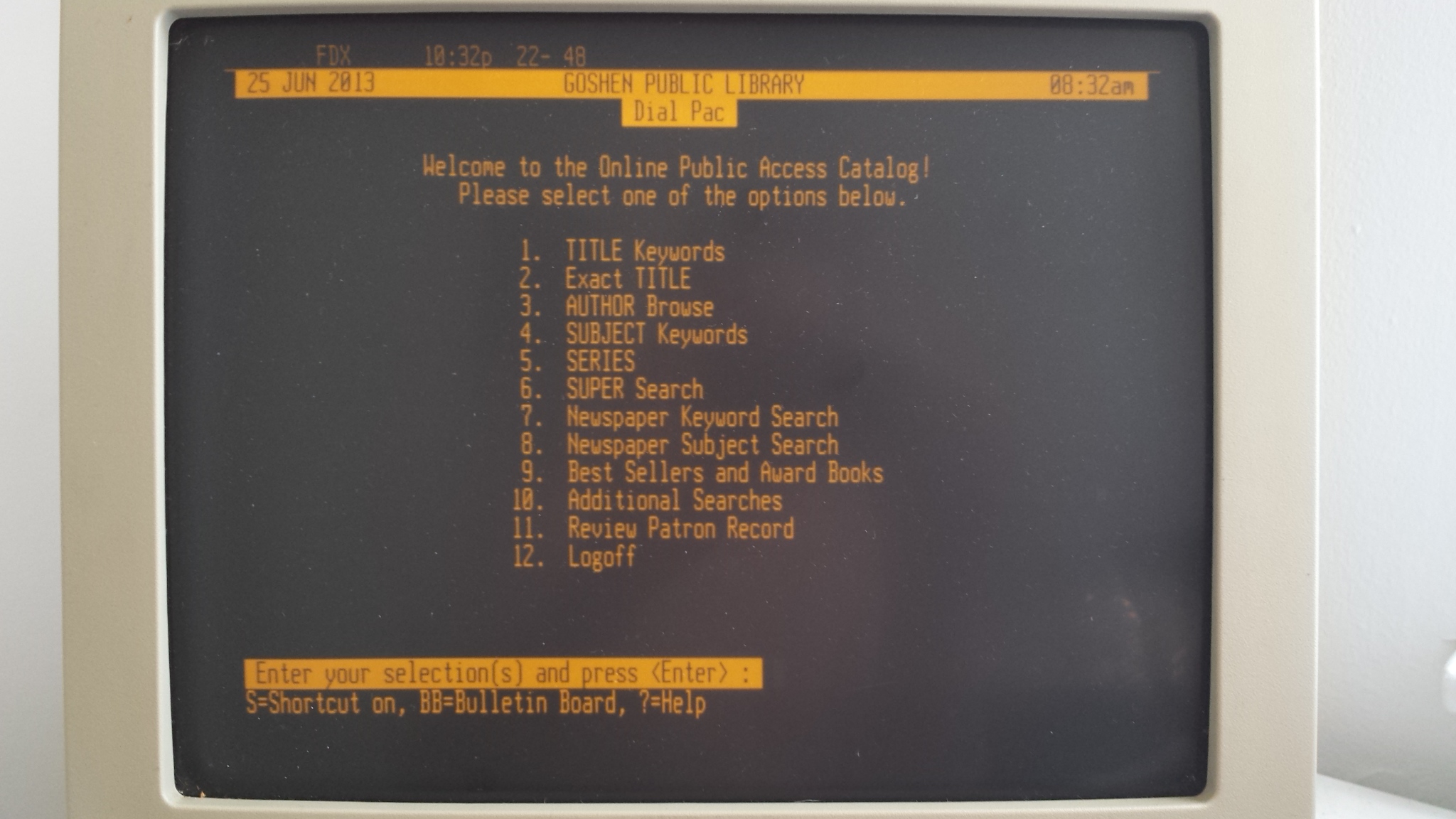
They let you draw two or three characters for the price of one as it were. ![]()
These things were important back in the day..
[ahull – Thu Apr 26, 2018 2:11 pm] –
If you are wondering what those 1. 2. etc and the numbers in brackets/circles characters are for, they are probably intended for use in this kind of menu.
They let you draw two or three characters for the price of one as it were.
These things were important back in the day..
Aw yeah, cool ![]()
I used to run a BBS by the way. Bit more modern than those though. PCBoard. Ami-X style. Used to write PPE modules.. uploader .diz extractors etc. and nice menu systems.
Well.. I am fed up of waiting for the round gauge style Autool X60 to come from China. I ordered one for £18 at the beginning of this whole thread.
I just checked Amazon, and it’s now available from Prime, at double the price. So I just ordered one. Will be here tomorrow ![]()
https://www.amazon.co.uk/Multi-function … autool+x60
It is definitely a different screen though ![]()
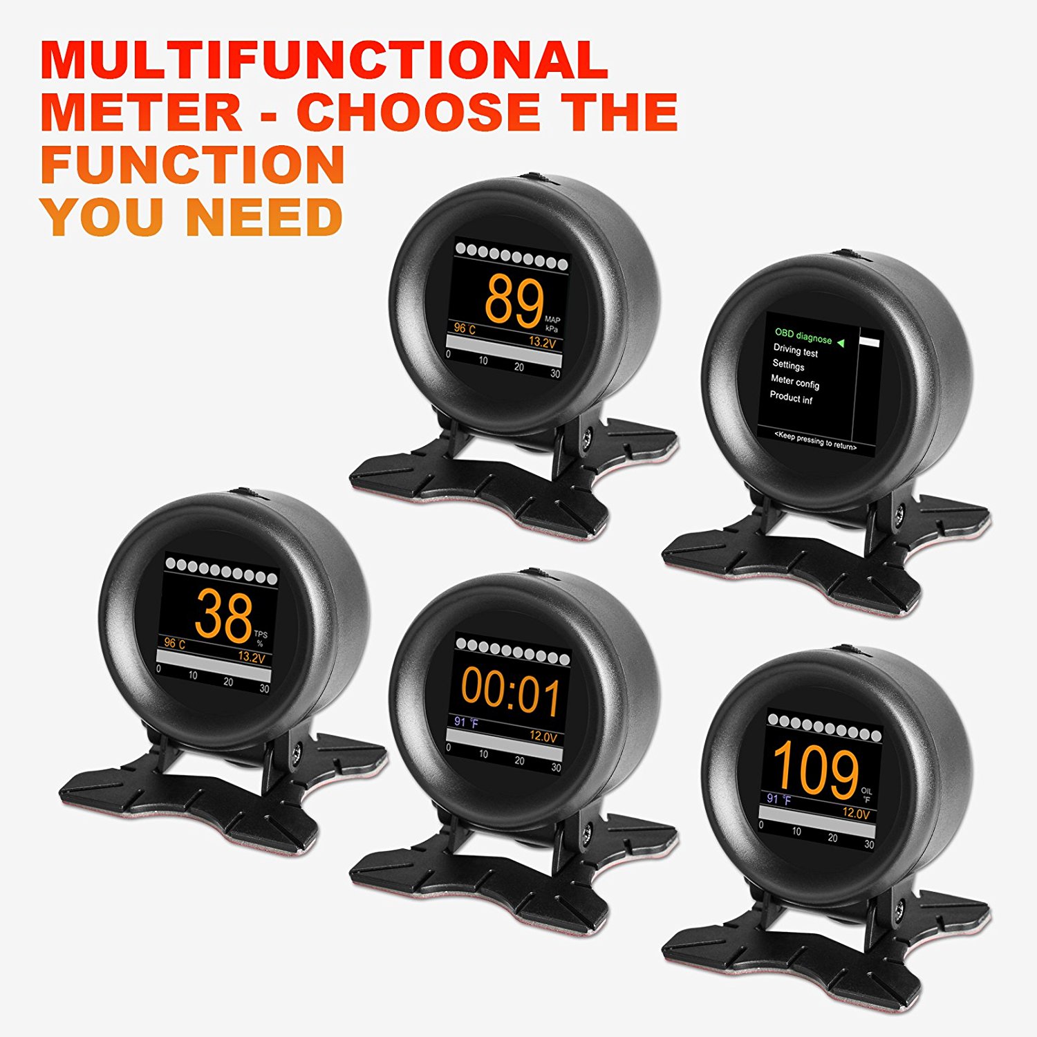
The descriptions are very similar. For example..
X50 – > 32-bit ARM CORTEX-M3 CPU, with 72MHz maximum operating frequency, in support of multiple high speed automotive communication protocols
X60 -> CPU based on 32 bit ARM CORTEX-M3 kernel; Maximum operating frequency: 72MHz; Support multiple high speed auto communication protocols.
Which in itself raises a question, the STM32F103 runs at “72MHz maximum operating frequency” but the GD part will run quite a bit faster, i.e. up to 80MHz (and we have even overclocked it to 120MHz).
The descriptions suggest the original design may actually have been based on the ST part, then later changed to the GD one.
It will be interesting to see what display the new one uses. I presume the firmware will be locked against prying eyes, but there is no harm in trying to take a peek at that too. My money is on the hardware being almost identical, save for the screen.
If we were *really* serious about accessing the firmeware on the GD32 part, and money was no object, then decapping it and connecting to the piggybacked flash chip would be my favoured option. ![]()
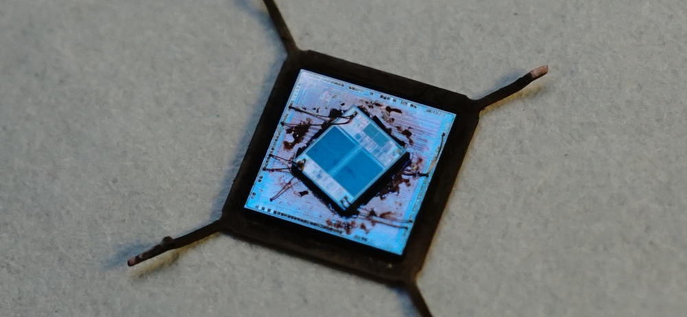
[ahull – Thu Apr 26, 2018 3:06 pm] –
Different, but very similar.The descriptions are very similar. For example..
X50 – > 32-bit ARM CORTEX-M3 CPU, with 72MHz maximum operating frequency, in support of multiple high speed automotive communication protocols
X60 -> CPU based on 32 bit ARM CORTEX-M3 kernel; Maximum operating frequency: 72MHz; Support multiple high speed auto communication protocols.Which in itself raises a question, the STM32F103 runs at “72MHz maximum operating frequency” but the GD part will run quite a bit faster, i.e. up to 80MHz (and we have even overclocked it to 120MHz).
The descriptions suggest the original design may actually have been based on the ST part, then later changed to the GD one.
It will be interesting to see what display the new one uses. I presume the firmware will be locked against prying eyes, but there is no harm in trying to take a peek at that too. My money is on the hardware being almost identical, save for the screen.
If we were *really* serious about accessing the firmeware on the GD32 part, and money was no object, then decapping it and connecting to the piggybacked flash chip would be my favoured option.

Yes I expect it to be identical except for the screen. I just hope we (you? ![]() ) can identify the screen!
) can identify the screen!
I have mine running at 128MHz by the way. It didn’t take to 120MHz. It’s not overheated or frozen yet. That’s about 80% clock speed increase over the stm32f103.
The official GD spec is “up to 108MHz”, i.e. 50% faster that stm32f103.
[ahull – Thu Apr 26, 2018 3:06 pm] –
Different, but very similar.The descriptions are very similar. For example..
X50 – > 32-bit ARM CORTEX-M3 CPU, with 72MHz maximum operating frequency, in support of multiple high speed automotive communication protocols
X60 -> CPU based on 32 bit ARM CORTEX-M3 kernel; Maximum operating frequency: 72MHz; Support multiple high speed auto communication protocols.Which in itself raises a question, the STM32F103 runs at “72MHz maximum operating frequency” but the GD part will run quite a bit faster, i.e. up to 80MHz (and we have even overclocked it to 120MHz).
The descriptions suggest the original design may actually have been based on the ST part, then later changed to the GD one.
It will be interesting to see what display the new one uses. I presume the firmware will be locked against prying eyes, but there is no harm in trying to take a peek at that too. My money is on the hardware being almost identical, save for the screen.
If we were *really* serious about accessing the firmeware on the GD32 part, and money was no object, then decapping it and connecting to the piggybacked flash chip would be my favoured option.
Hey going back to the square screen..
Well, I found online that the same driver (ST7789) also supports different resolutions, and there are panels for sale at 240*240 with ST7789. ILI9341_STM32 allows you to set TFTWIDTH and TFTHEIGHT in the .h file too.
Also, I found that the A202 model of this device, also has a square screen…
So i’m feeling hopeful!
My round version (X60) has just arrived in the Amazon locker so I can pick it up on my way into work now but I won’t be able to do anything other than open it up and take photos until later in the weekend.
montage -label '%t' {1..835}.png -tile 32x -geometry +1+1 -frame 5 -shadow -stroke "#000000" -bordercolor "#B3997A" -background none montage0.pngThere’s no markings that help. It’s approx 1.5″ diagonal, glued to a round-ish piece of glass. 24 pin ribbon says CXTA on it.
I think it will be a 1.54″ 24pin, maybe like this one: https://www.alibaba.com/product-detail/ … 27041.html
or similar. that says st7789 too. it’s 320×320 that one though, so I guess these 1.54″ ST7789 screens come in various resolutions.
The whole thing is quite a bit smaller than I expected!
Arrrgh. Another problem. There aren’t so many pin/debug headers broken out. There’s just a J2. Not a J1 and an J2. It might not have UART broken out ![]()
After monitoring the mystery chip, and maybe monitoring the LCD for its init sequence (if its SPI), I’ll simply try the existing working code on it, just in case it is an ST7789 at 240*240. Such a panel does exist: https://www.adafruit.com/product/3787
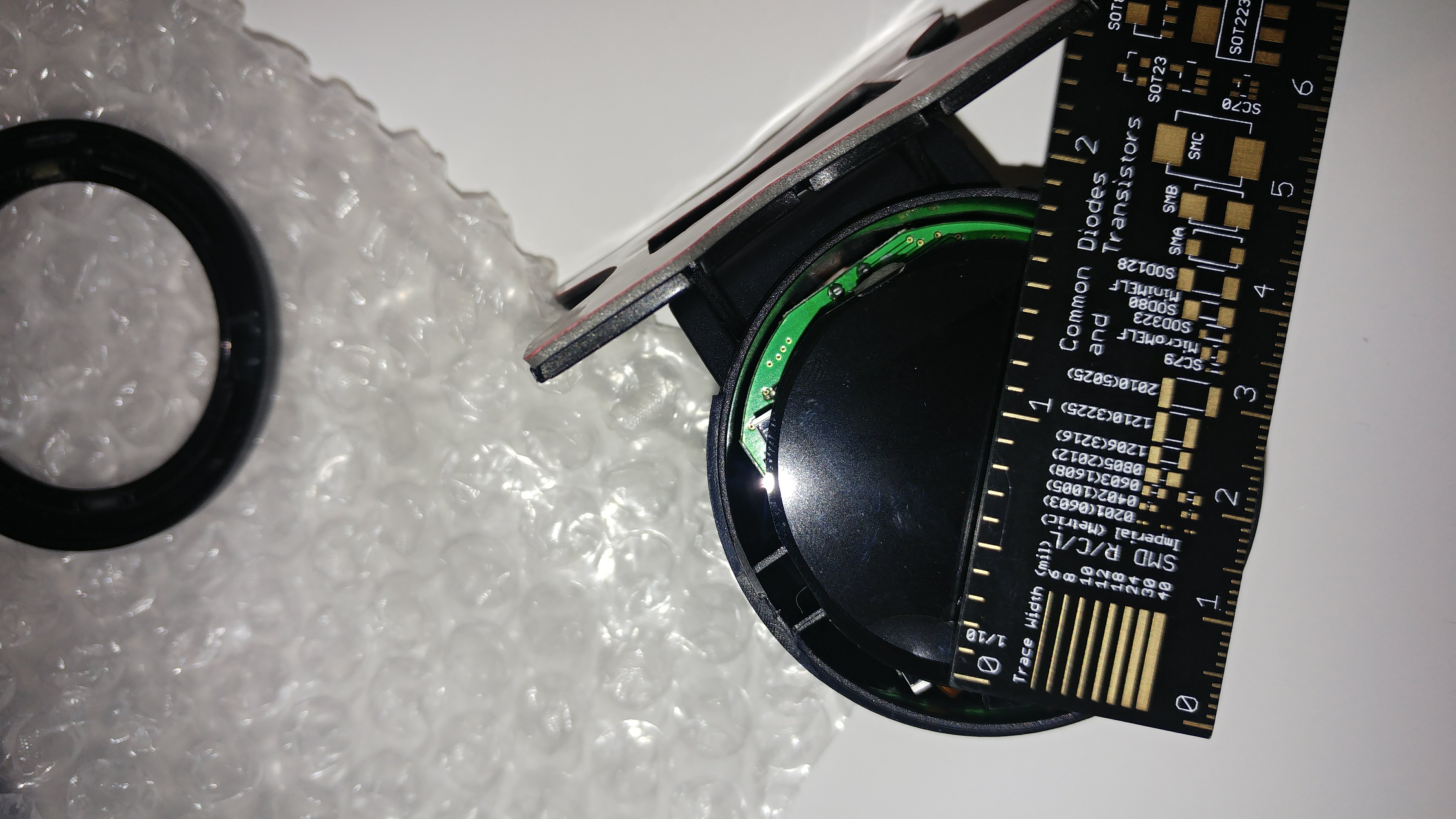
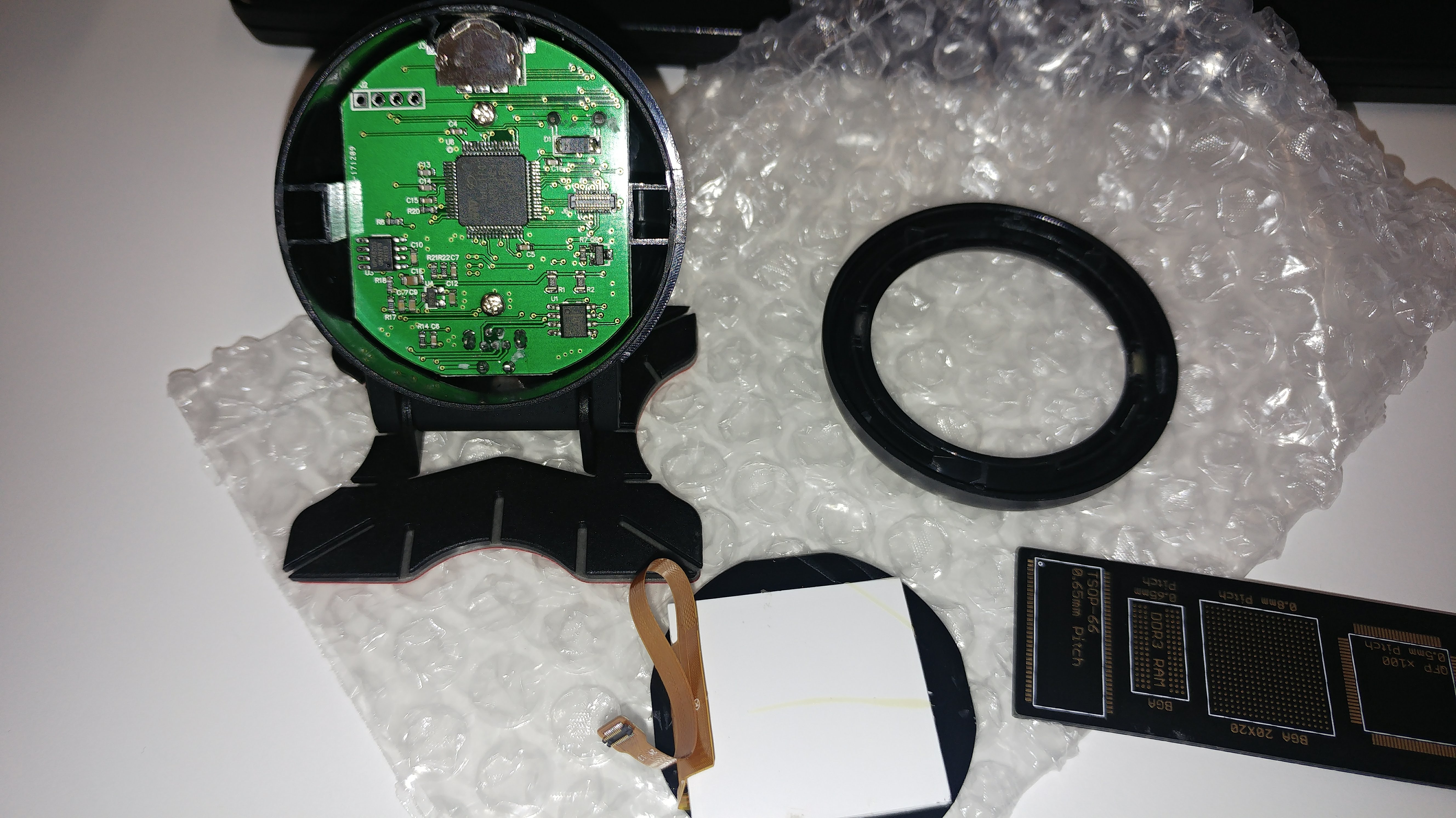
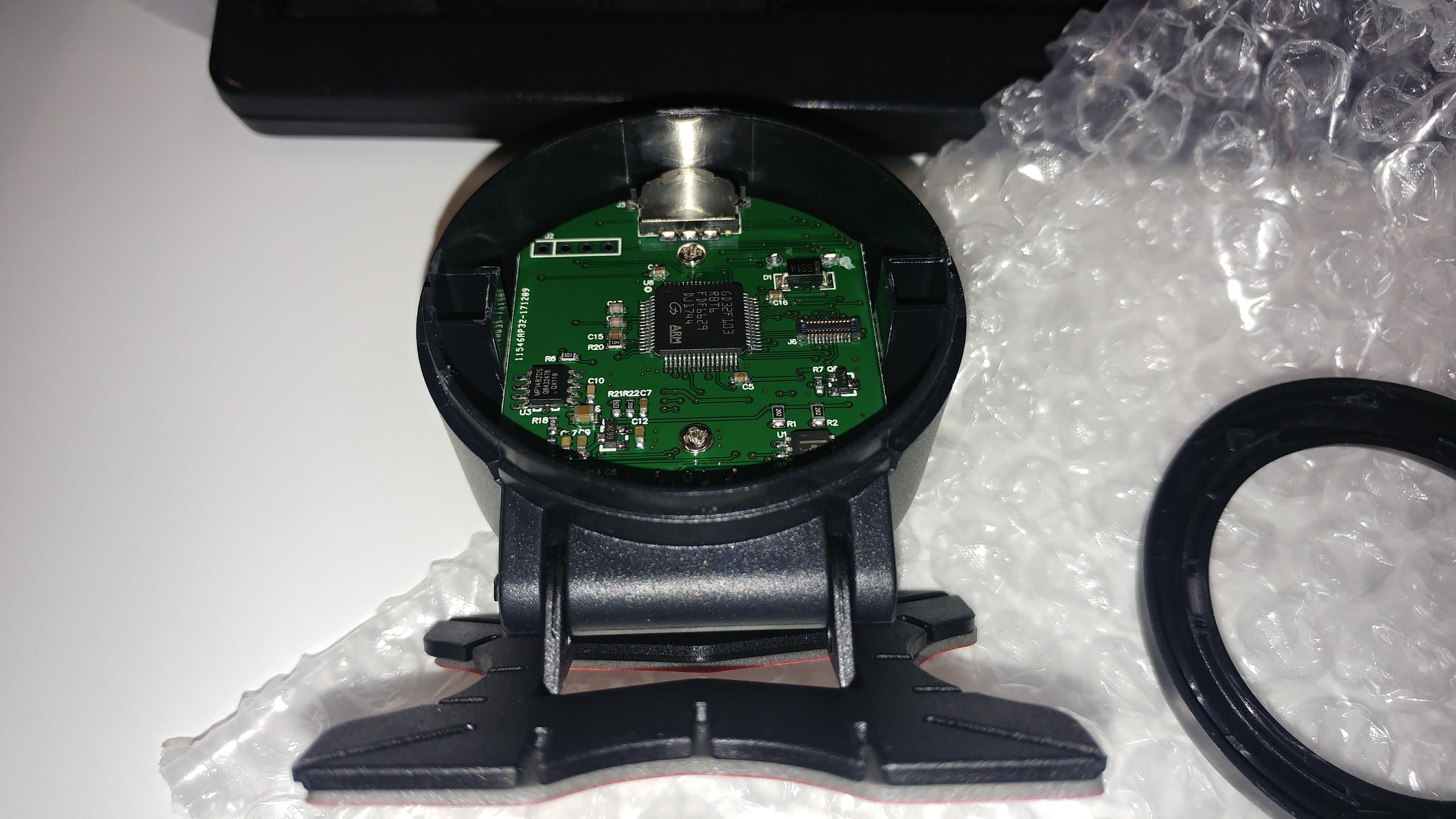
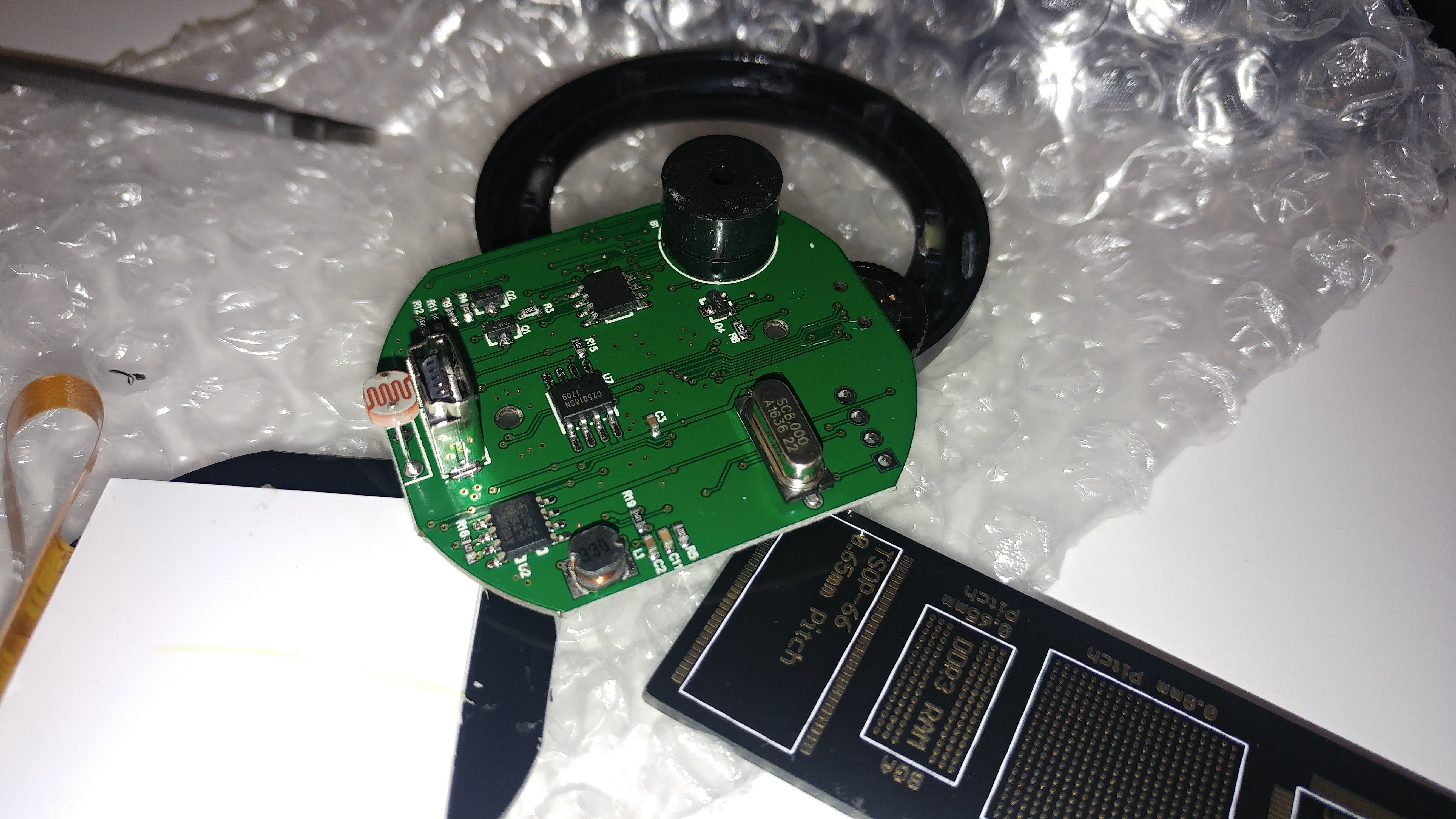
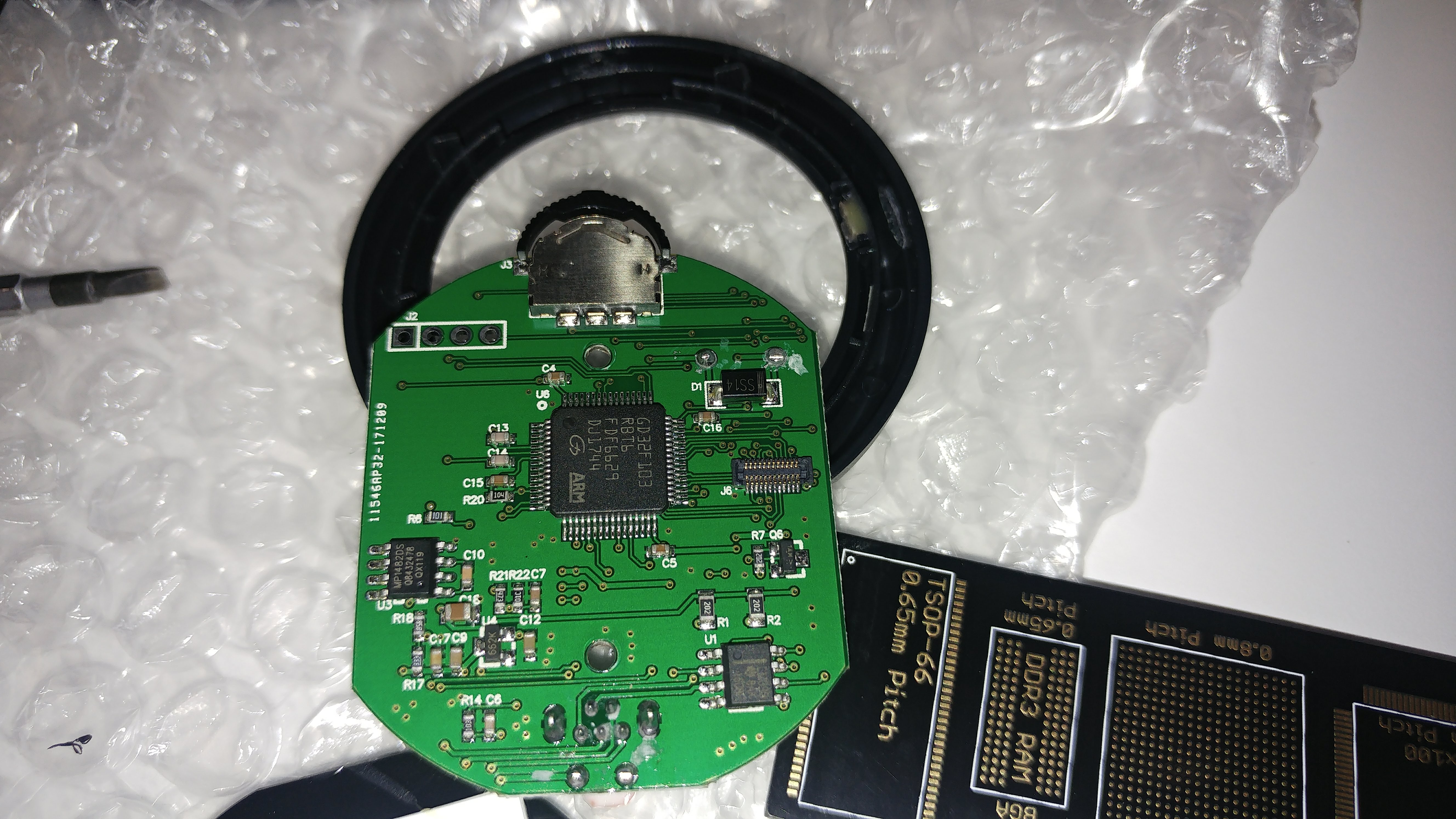
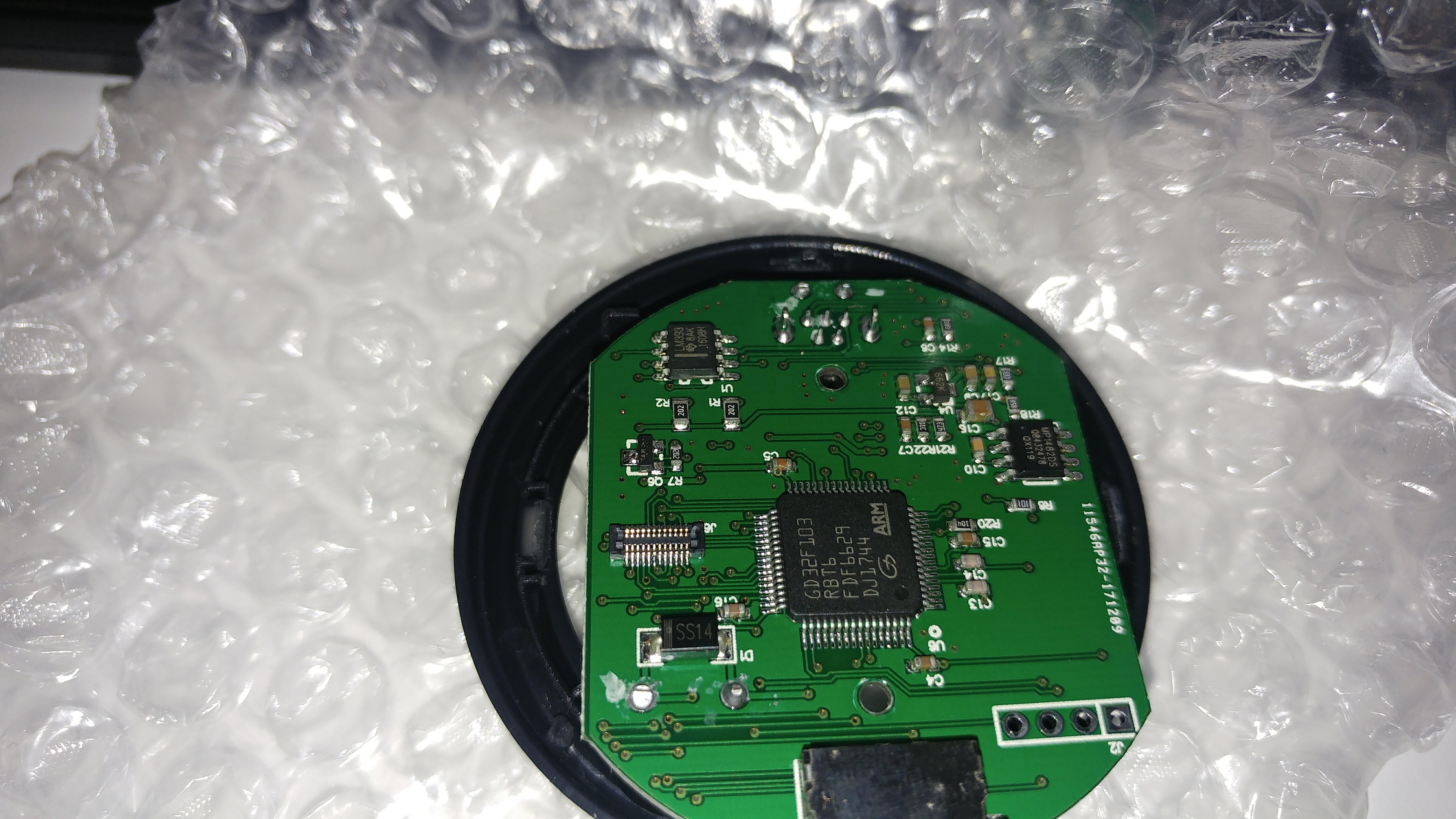
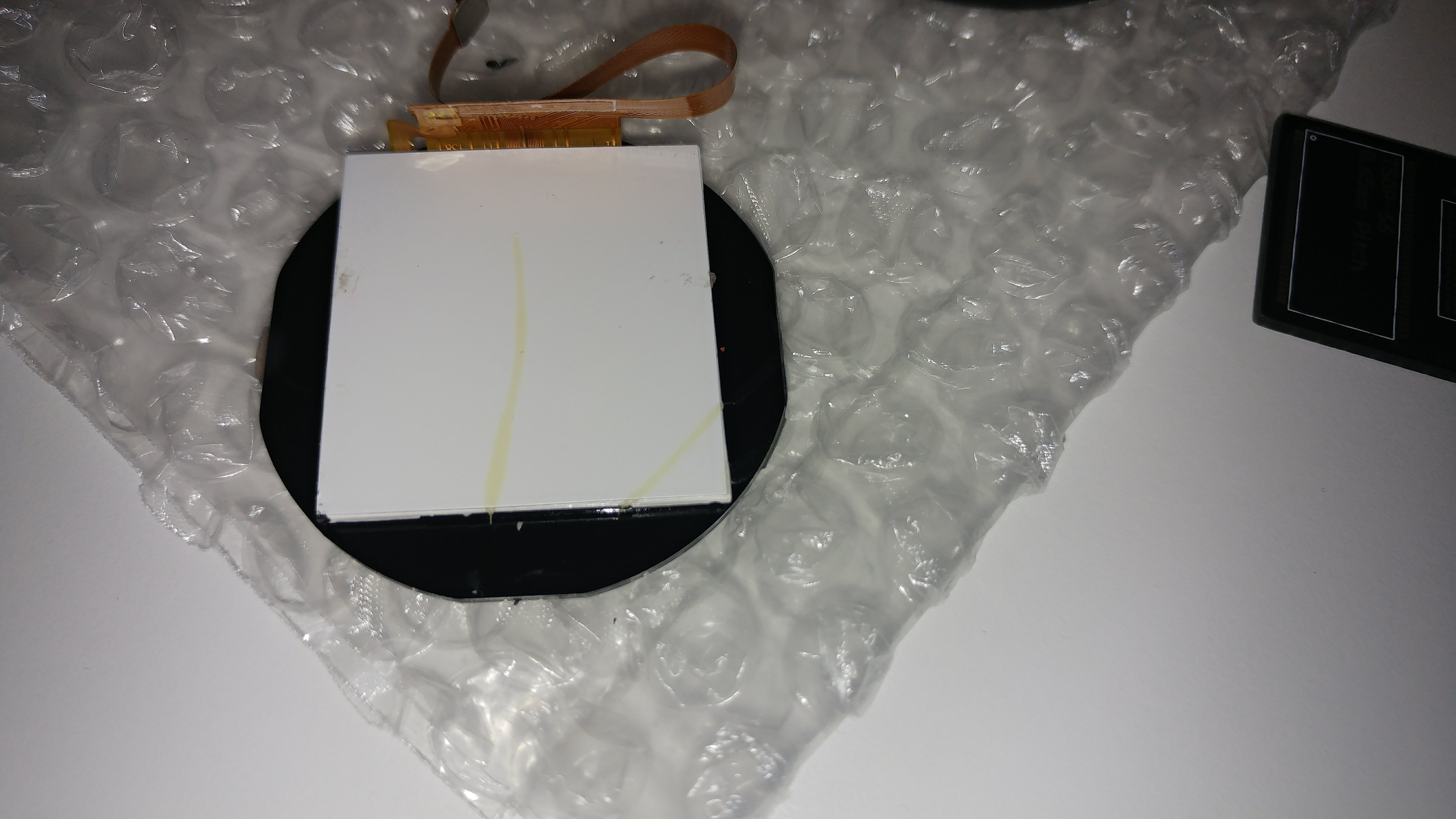
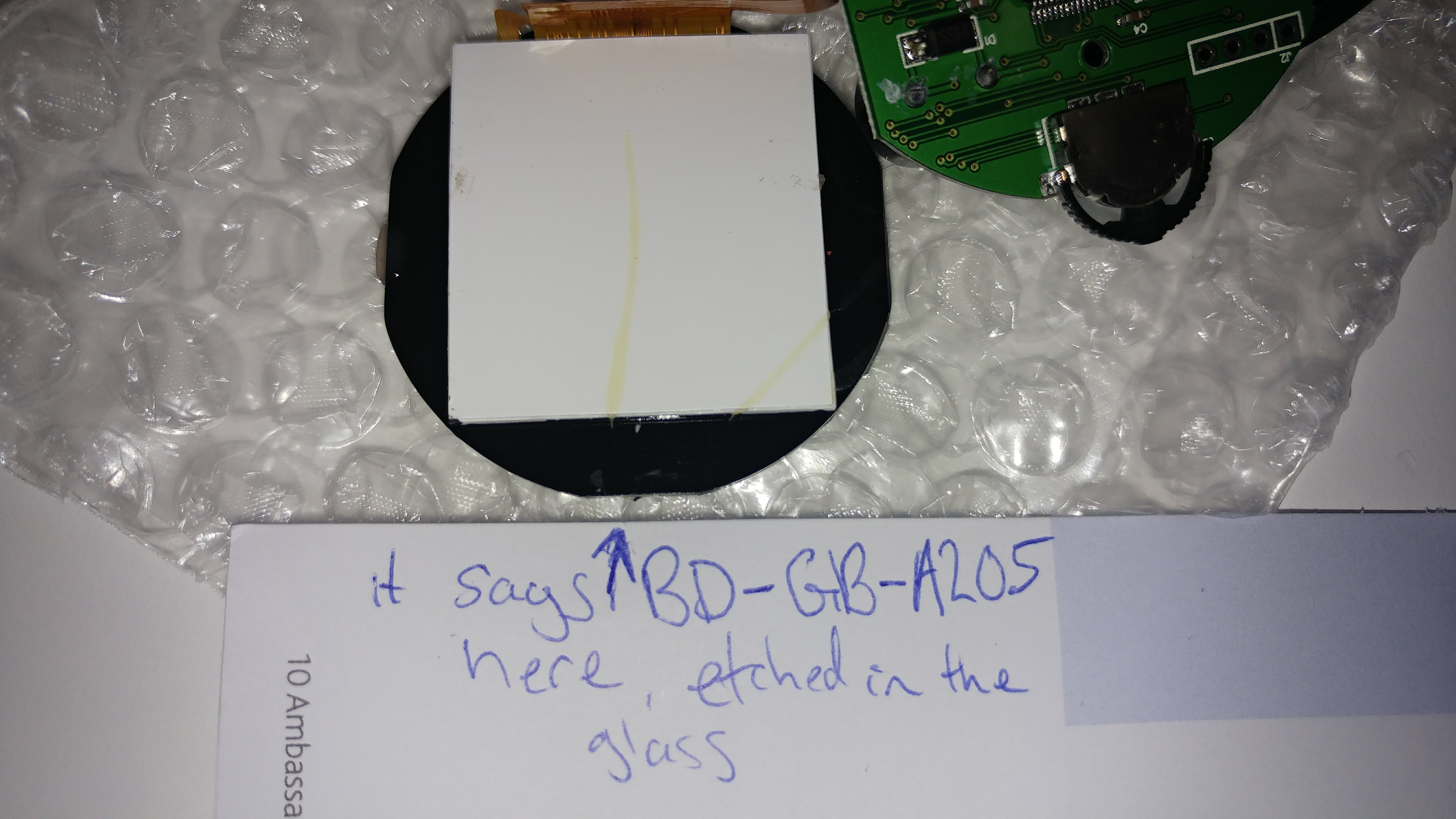
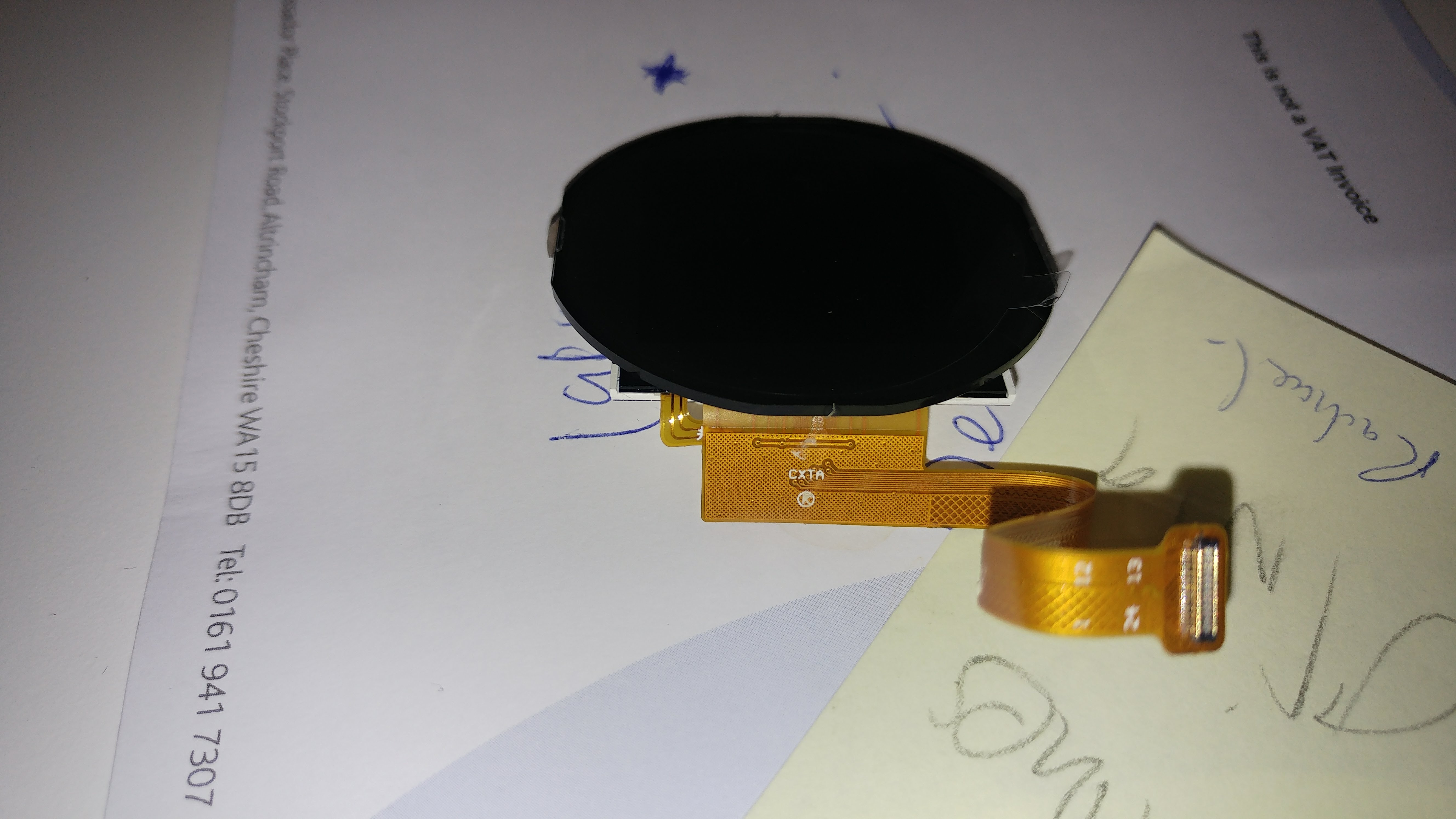
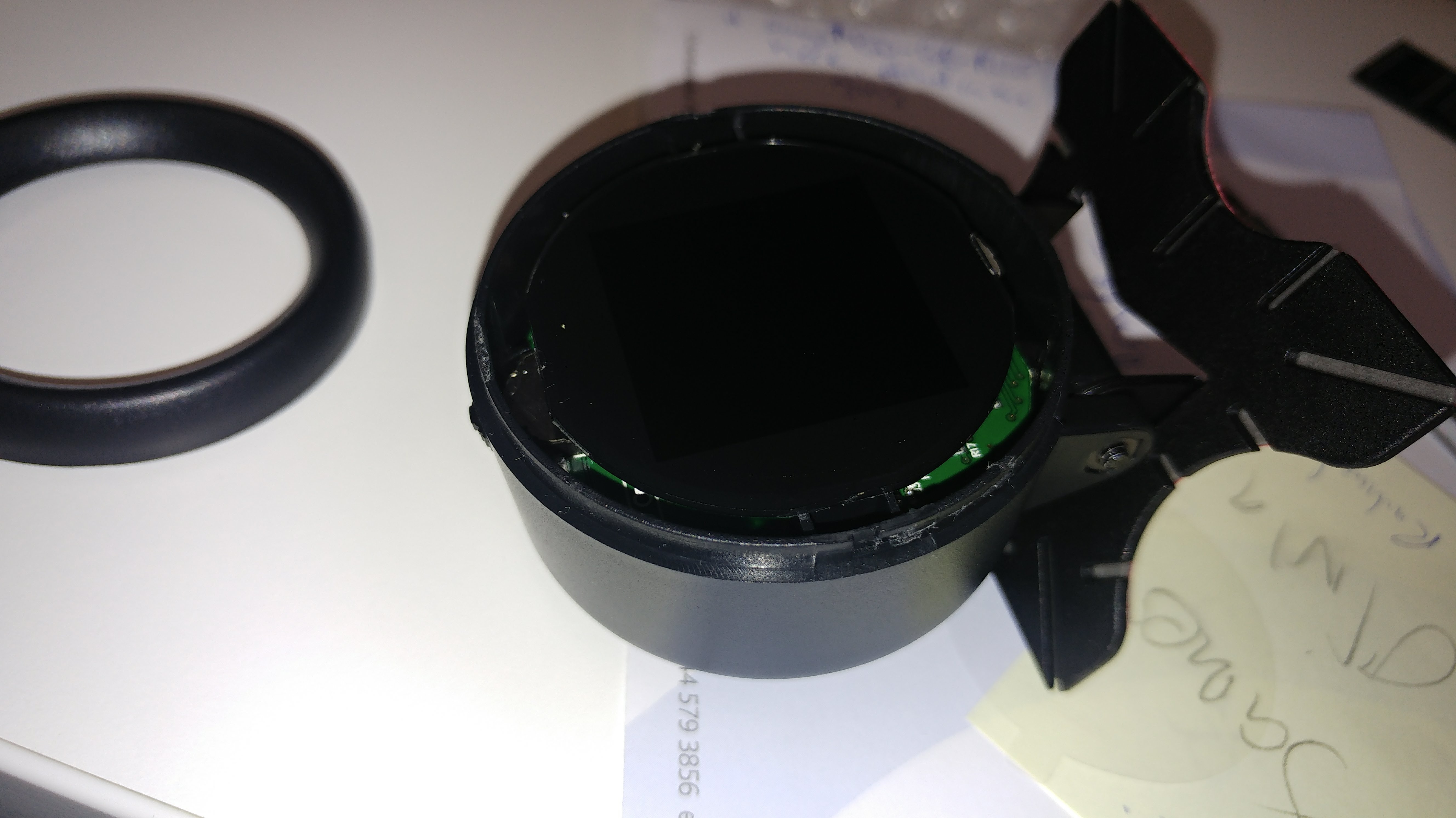
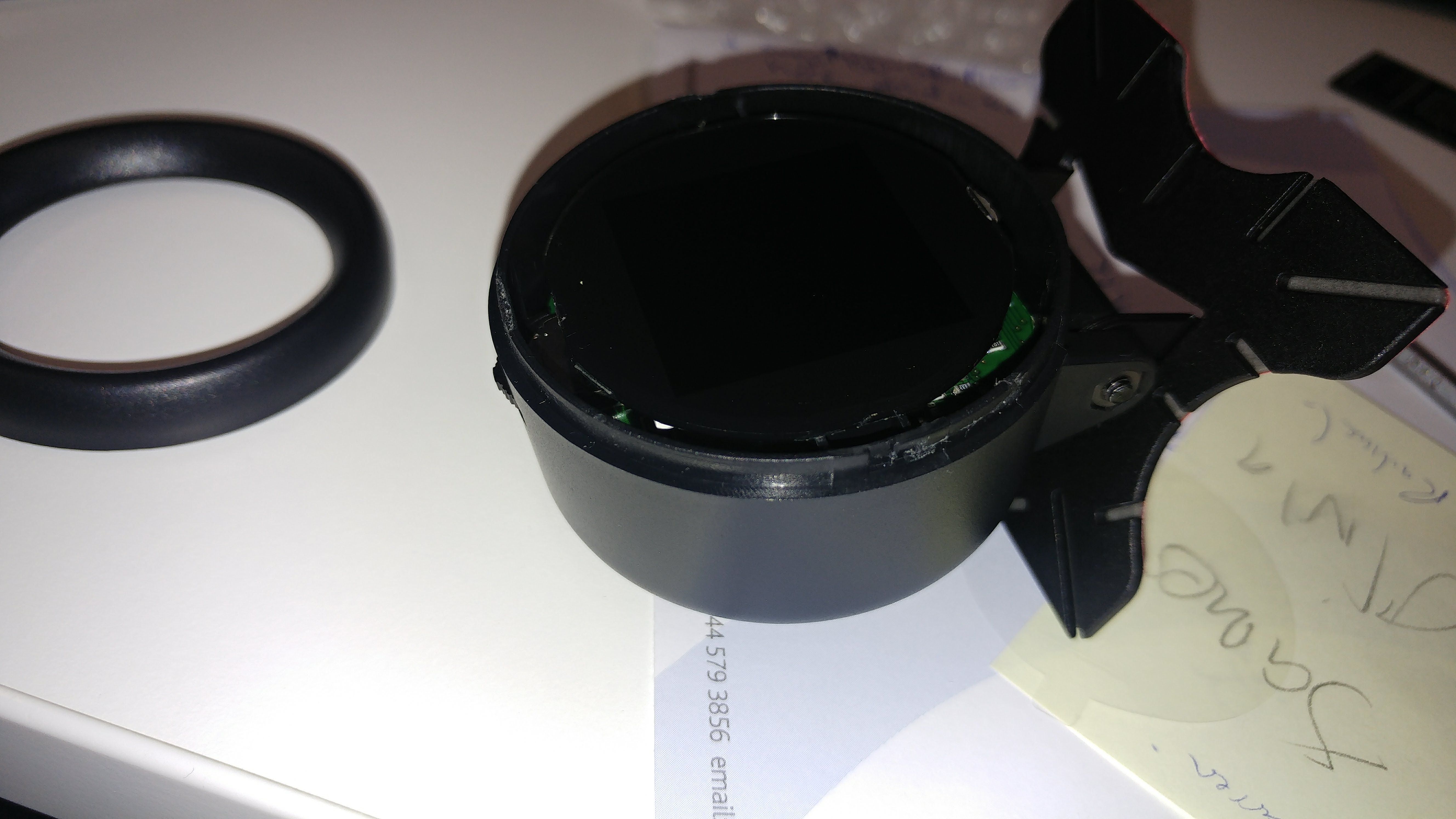
Whatever it is, it is most probably a jellybean part and there will be some kind of a driver for it.
I’m pretty sure we will be able to get it going. BTW is the mystery chip on this unit too? Is it also unmarked?
https://www.alibaba.com/trade/search?fs … =round+tft
Probably this was the least cost option in the size they required.
[carl0s – Thu Apr 19, 2018 10:06 pm] –
Pin outs for the headers, looking from the top of the board where the LCD FFC socket is, with the buzzer at the bottom right.J2
1 (left) – SWDIO
2 – SWDCLK
3 – GND
4 (right)- VDDBoard needs external power to use STLink though. VDD should just be connected to ‘target vcc detection’ pin of STLink (pin #1)
J1
1 (top) – GND
2 – nothing
3 – PB10
4 (bottom) – PB11With the board still in the same orientation, 3 way switch / jog thingy pinouts:
Rotate Left: PC14
Push Middle: PC15
Rotate Right: PC13
Right. So this X60 PCB only has a J2. I did a visual inspection of the traces through the VIAs and thankfully it is still SWDEBUG. So I can program the device.
It’s a shame the UART3 isn’t broken out like it is on the bigger brother.
This is what my visual inspection revealed. From the side that’s actually labelled J2. Obviously I have the order inverted here from what I wrote about J2 on the X50 board:
J2 on X60 model:
1 vdd (pin64)
2 nowhere, maybe ground ? don't have a meter to hand
3 SWCLK
4 SWDIO
[ahull – Fri Apr 27, 2018 11:35 am] –
Its interesting that they went with a square display, as there do appear to be round displays available at fairly reasonable prices.https://www.alibaba.com/trade/search?fs … =round+tft
Probably this was the least cost option in the size they required.
I was looking at these (a lot!) last night, thinking about doing my own in a nice metal & glass fronted gauge. but a lot of them are MIPI, and only Alibaba sellers at the moment, no Aliexpress sellers. I would really like to get my hands on an SPI round one with an ILI or ST driver.
Would be nice to have something more high-end looking, like this:
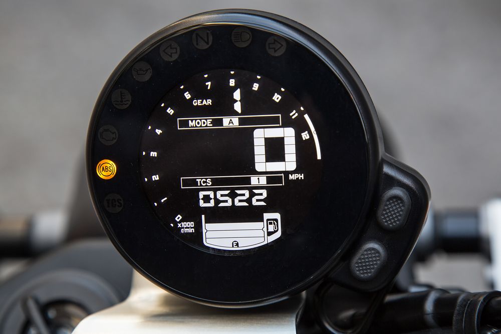
[ahull – Fri Apr 27, 2018 11:26 am] –
It is probably a similar display to the X50, since most of the other circuitry looks identical, but I guess it could also be a 1.5″ OLED, something like -> https://www.ebay.com/itm/1-5inch-OLED-M … SwdXdadsswWhatever it is, it is most probably a jellybean part and there will be some kind of a driver for it.
I’m pretty sure we will be able to get it going. BTW is the mystery chip on this unit too? Is it also unmarked?
Yep, same Mystery chip.
With a little imagination, you can have whatever UI you want.
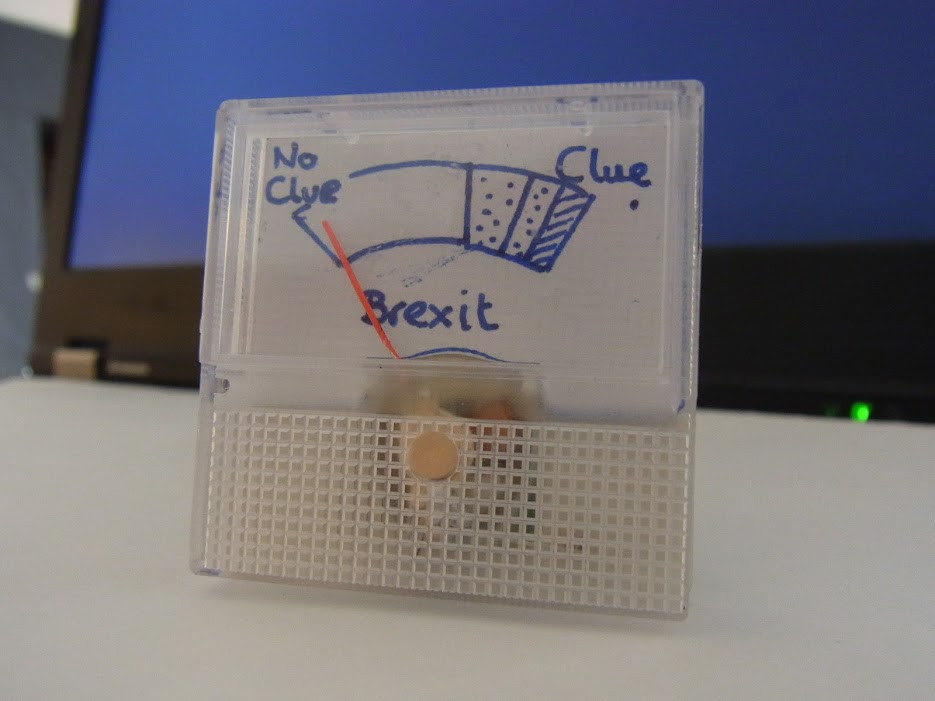
We can overwrite all of the Chinese characters and the images with whatever we fancy. 2Mb of flash gives you a lot of options.
[ahull – Fri Apr 27, 2018 1:29 pm] –
Would be nice to have something more high-end looking, like this:
With a little imagination, you can have whatever UI you want.
We can overwrite all of the Chinese characters and the images with whatever we fancy. 2Mb of flash gives you a lot of options.
![]() I think we’re on the same page with that gauge.
I think we’re on the same page with that gauge.
Although it is similar, it includes some new ones, a few more arrows and another box drawing set.
montage -label '%t' {8837..9682}.png -tile 32x -geometry +1+1 -frame 5 -shadow -stroke "#000000" -bordercolor "#B3997A" -background none montage6.png
Firstly it has a 24pin FPC connector, 0.4mm pitch dual-row, as seen in mobile phones, making it a pain to hook up to. I may hook up fine wires to the MCU legs.
Secondly, the pin-outs don’t look good for SPI. It seems to be connected to general purpose IO on the MCU.
Here are the pins that I can see go from MCU to LCD connector.
PB5

PB15 (WAS TFT_MOSI ON X50 MODEL)

PA11

PA13 (WAS TFT_D/C ON X50 MODEL)

PA15 (WAS TFT_RST ON X50 MODEL)

PC6

PC7
No CLK or EN/SS ?
PB1 BACKLIGHT (SAME AS X50 MODEL)
0x000000 (0) %—- Western Roman Encoded fonts 24×24, these are serifed or ‘Book’ face
0x018C48 (101448) %—- Chinese 24×24
0x09B520 (636192) %Western Roman Bold 24×24
0x0B4168 (737640) %—- Chinese Bold 24×24
0x136A40 (1272384) %— ASCII order sans serif 8×16 — probably the main diagnostic (back channel) font.
0x137030 (1273904) %— ASCII order sans serif 16×24
0x138200 (1278464) %— ASCII order sans serif 16×32
0x1399C0 (1284544) %— ASCII order sans serif 24×48
0x13CF32 (1298226) %—- 10 Large Arabic numbers 40×72 1 or more bytes in-between each number May be some other (pad) bytes before the (-) minus mask.
0x13E157 (1302871) %— icons 32×48
0x13F460 (1307744) %— start of text
0x159406 (1414150) % end of text start of color graphics — next up is to decode the offsets into this area
@carl0s – I wouldn’t worry too much about soldering to that display, I’m sure we can figure it out from some pictures and a little imagination, without needing to resort to microsurgery. The connector looks like some of the Nokia phone connectors. This sort of thing -> http://andybrown.me.uk/2012/06/05/nokia … no-mega-1/ but I think the pin layout is different.
The vast majority of displays are very similar. Can you give me some good macro shots of both sides of the FPC, and some good shots of both sides of the main PCB, so we can follow the tracks and vias.
I would start by identifying all the GND pins on the display connector using the buzzer on your multimeter. Next I would see which pins go where from the GD32 – then perhaps try to figure out which pins look like they might have a backlight LED or two attached. I’m assuming this is a TFT not an OLED display. Again use the multimeter in continuity buzzer or diode mode between GND and the pins to see if there is a dim flicker from the display, it will be very dim I would imagine. You might not get any result for this as the LEDs may be in series.
While we are figuring that out, you could dump the X60 flash and we can see if it is broadly the same as the X50
here is a quick dump of the color image offsets and centered sizes:
0x159432 % 220×160
0x172F11 % 88×180
0x17E977 % 220×80
0x18AFA4 % 320×84
0x19EAE6 % 320×72
0x1AEDE2 % 320×100
0x1C5D98 % 320×72
0x1D3EC8 % 320×72
0x1E4548 % 320×72
0x1F572F % 320×46
Here is a dump of the images rotated an mirrored. I ran some through a reverse image search tinEye and google. The cxat trademark does not show up, which I find curious as it is in there three times. Wonder if it really is a registered trademark? If registered why does it not show up in a reverse image search?
The URL works and leads to a Malaysian website where some of the other graphics are found.
Google giggle gurgle seems to want to auto correct cxat to cat. The car image is a generic clip art piece which show up in a lot of places mirrored or color shifted. Gurgle says it is a Ferrari.

- cobd18428a.jpg (73.75 KiB) Viewed 641 times
The pinouts (SDA on 5 and SCL on 6) match an eeprom, but the VCC and GND pins are opposite, also the amount of data coming to/from is tiny. LIke 1 or at most 2 bytes per read/write. I’m not sure what it is. It might not even be i2c.. the decoder might just be spewing out rubbish.
Here’s a capture of what it does on power-up. view with dsview from dreamsourcelab:
http://www.internetsomething.com/autool … y-chip.dsl
I have nothing that will read the .dsl file, so i can’t examine that information, but if there is little data being exchanged, then perhaps the device is a sensor of some sort (compass, gyro, temperature or whatever).
[ahull – Sun Apr 29, 2018 3:49 am] –
@carl0s – I wouldn’t worry too much about soldering to that display, I’m sure we can figure it out from some pictures and a little imagination, without needing to resort to microsurgery. The connector looks like some of the Nokia phone connectors. This sort of thing -> http://andybrown.me.uk/2012/06/05/nokia … no-mega-1/ but I think the pin layout is different.The vast majority of displays are very similar. Can you give me some good macro shots of both sides of the FPC, and some good shots of both sides of the main PCB, so we can follow the tracks and vias.
I would start by identifying all the GND pins on the display connector using the buzzer on your multimeter. Next I would see which pins go where from the GD32 – then perhaps try to figure out which pins look like they might have a backlight LED or two attached. I’m assuming this is a TFT not an OLED display. Again use the multimeter in continuity buzzer or diode mode between GND and the pins to see if there is a dim flicker from the display, it will be very dim I would imagine. You might not get any result for this as the LEDs may be in series.
While we are figuring that out, you could dump the X60 flash and we can see if it is broadly the same as the X50
The display is really tiny though. I would still like to see if we can work it out, but I’m currently going down a MIPI rabbithole.
I ordered some 1.3″ round displays with ST7789 last night, which are SPI. I then realised that these are likely to be the same size as my 1.54″ screen but with the corners cut off / covered.. Too late now though, I ordered last night from dhgate.
I ordered an STM32L4R9I-DISCO (from Amazon would you believe) but then cancelled it when I DISCOVERed that the stm32s with MIPI-DSI (display interface, as opposed to CSI for Cameras), which is the stm32l4r9 and the stm32f469 and f479, well, they only have 2 MIPI data lanes / channels. Bit like PCI-express lanes. Some of the displays out there, including the nice 3.4″ one on Alibaba with a stunning 800×800 resolution, well, they need 3 lanes, or at least the ILI9881C chip on them is set up for 3 lanes. There’s a register and some ‘external pads’ (jumpers?) you can set, but as far as I can tell, if it’s set for 3 lanes, then to change it to 2 lanes, requires changing LANCEL from a 0 to 1, and that’s an external pad (meaning jumper?) rather than a register.
So now I’m acquiring MIPI displays (sending alibaba enquiries anyway) and hoping to get a board with the SSD2828 chip on it, which converts RGB (and maybe SPI.. not sure) to MIPI up to 4 lanes. There were loads of these boards available but none on Aliexpress any more.
The Amazon Echo Spot has a 2.5″ 480×480 screen that looks interesting. MIPI again though.
[ahull – Sun Apr 29, 2018 6:19 pm] –
Looking at Andy Brown’s Workshop pages and in particular -> http://andybrown.me.uk/2013/02/24/gener … ing-board/ I think it would be worth checking to see if the connector we are looking at is a good match for the Nokia one. The Nokia displays would be a good choice for this kind of device as they are ubiquitous and cheap.
Hi Andy!
It’s not the same connector, no.
It’s slimmer, and also, it has notches in the ends. See below.
A lot of screen seem to use the Panasonic AGX series, then there’s the Molex 504208-2410 (24pin receptacle), which uses 504248-2410 plug, but it’s not that either.
It doesn’t look like the JAE or JST either.
I think a thorough search through mouser/digikey might be in order ![]()
I have just ordered some nice screens that use MIPI though. another project. see if I can do something with them and the SSD2828 bridge IC.
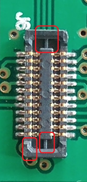
I have a GD32F130C6 and GD32F130C* which I cannot programm them with ST link v2.
Thanks in advance!
… and here -> http://wiki.stm32duino.com/index.php?ti … 103C8_mini
If you have an ST-Link or clone, you then need to identify Gnd, SWDIO (PA13) and SWCLK (PA14) connect those to your ST-Link and progam as per most of the STM32F103 board. There is a GD32 version of the bootloader, but I don’t know how up to date it is.
If the firmware is locked on your device, you may not be able to back it up, and may have to do a complete erase when you first flash any new code to it.
@carl0s may be able to fill in a few more details, as I last played with my red pill GD32 board a couple of years back.
[ahull – Thu Jun 21, 2018 8:25 pm] –
I used an ST-LinkV2 clone to program mine. This thread has a few clues -> viewtopic.php?f=28&t=604
… and here -> http://wiki.stm32duino.com/index.php?ti … 103C8_miniIf you have an ST-Link or clone, you then need to identify Gnd, SWDIO (PA13) and SWCLK (PA14) connect those to your ST-Link and progam as per most of the STM32F103 board. There is a GD32 version of the bootloader, but I don’t know how up to date it is.
If the firmware is locked on your device, you may not be able to back it up, and may have to do a complete erase when you first flash any new code to it.
@carl0s may be able to fill in a few more details, as I last played with my red pill GD32 board a couple of years back.
Yes that’s right. I had issues with the tvcc pin I think it was – target vcc or vdd, used to check/measure target voltage. Had to put that to a different +3.3 maybe. I talk about it near the start of this thread I think. Also I had to have the target device powered externally as the st link wasn’t able to supply enough power for the whole device.
My version is GD32F130 and I see here there’s about GD32F103 ![]()
But your ideas might apply in my case. I’ll see what I get.
For future questions can I post here or it would be thread trashing?
Have a cool weekend!
I have found to test a chip more closely to the one used by carl0s: GD32F103C8 and I’ve had some luck with it but, I’m still in the woods… I’ll use my old thread to ask questions before I get to the other uC.
@ carl0s I haven’t been able to find the pin you’ve mention here on the thread. I’ve tried to use more powerful source for 3.3V, but nothing has changed yet.
Please have a look here: viewtopic.php?f=3&t=3753&p=46635#p46635

