https://www.aliexpress.com/item/STM32-A … 02179.html
So what would it take to get this to work?
Has anyone used this?
Depending on what interfaces you need:
– for “standard” stuff you could try the Roger’s repo (or maybe my repo because it is a bit more developed), see http://stm32duino.com/viewtopic.php?f=39&t=1976.
– for any “special” stuff you should use the official STM core or Daniel’s generic core.
it should work with STM32GENERIC, mine do ![]()
there’re multiple versions of STM32GENERIC, daniel, huaweix??
stephen
that reminded of an A10 aircraft with German markings, nick named as the Devils Cross in Tom Clancy’s Red Storm Rising.
i’ve used it with both of the STM32GENERIC cores; dan- & hua-. and it’s listed in their board manager as a Black F407, a top level menu then selects the particular VE/ZE/ZG variant.
one of advertisers had a reference to ‘compatible tft displays’, albeit a bit pricey, i’ve since seen tft displays with identical “pins count & pin naming” quite a bit cheaper.
stephen
Are there any example programs for this board? My board came with a mass storage program making the onboard flash and sd reader viewable on the computer… (just about its unstable though)
In the STM32GENERIC theres a a zgt (M4 DEMO) listed… is that this board?
Something else I cant find is the info on the flash or the sd reader… What pins or serial/SPI/i2c are they connected to?
Also what pins are the led indicators connected to?
Also program upload and serial print debugging… Whats the best way to do that? From what i can tell the USB on board cant be used for any of that?
Ive used an STlink to reflash some f103 boards but i dont remember it being used for serial debugging?
So whats the best way to go about it all?
there’s also a soic footprint on the back, some people already have done timing tests on SRAM and have posted their results.
2 makes. apart from fast and faster, samsung is one ![]()
yes, i have 10 of each for installation sometime. getting my resources together is worse than trying to herd a cat.
the VET chip is smaller and mounted square to the pcb, not rotated 45 degs
the ZGT is much the same size, way higher pin count and higher pin count side connectors.
i thought i’d posted connectors and such, i’ll gather what i’ve got and post/repost it.
all 3 are in at least one of the STM32GENERIC cores, sub-menu under Black F407 istr
unsure on the libmaple cores.
stephen
But what about the propper way to upload and debug?
i always use st-link method, mainly 20way cable route with blue/white egg shape st-link, although i use the usb stick st-link type for blue pill etc
i’ve never had any real success with the other methods, worst i’ve had on st-link is the odd press reset or even rarer a power disconnect/connect
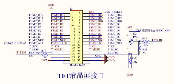
tft connectors change in size 34 v 36 and also change from header to socket on these boards.
pin name wise there are a number of displays that seem usable.
srp
So yeah I have one of those cheap STlink usb dongles…
So that for firmware uploading then.
What about debugging? Can the stlink be used? i assume its not by the normal serial print?
about the usb stick, istr it needs a hardware modification and has to be the right mcu / pcb layout. also been posted, try hackaday i think
srp
And what do i need to modify the stmlink for?
st-link – you need to add the connection for debug serial output (trace signal) also needs a software mod/install and istr that the sticks may have either f101 or f103; also i think only one can be or one is easier to be modified, try looking on instructables
- ve-tgt.png (57.07 KiB) Viewed 293 times
- zgt-tft.png (237.61 KiB) Viewed 293 times
zgt ok
ze too big
ve also too big, but i think it’s on the wiki
- STM32F407ZGT-Devils-Cross-Schematic.pdf
- (72.94 KiB) Downloaded 18 times
For starters I dont have a SWD pin set, but i do have a serial pin RX TX 5v GND, I also have a jumper called j8 and thats 8 pins but no indication for what…
I also dont have an eprom chip. but i do have a 12meg WS flash chip…
Also on the underside of my board i have a SDRAM footprint…
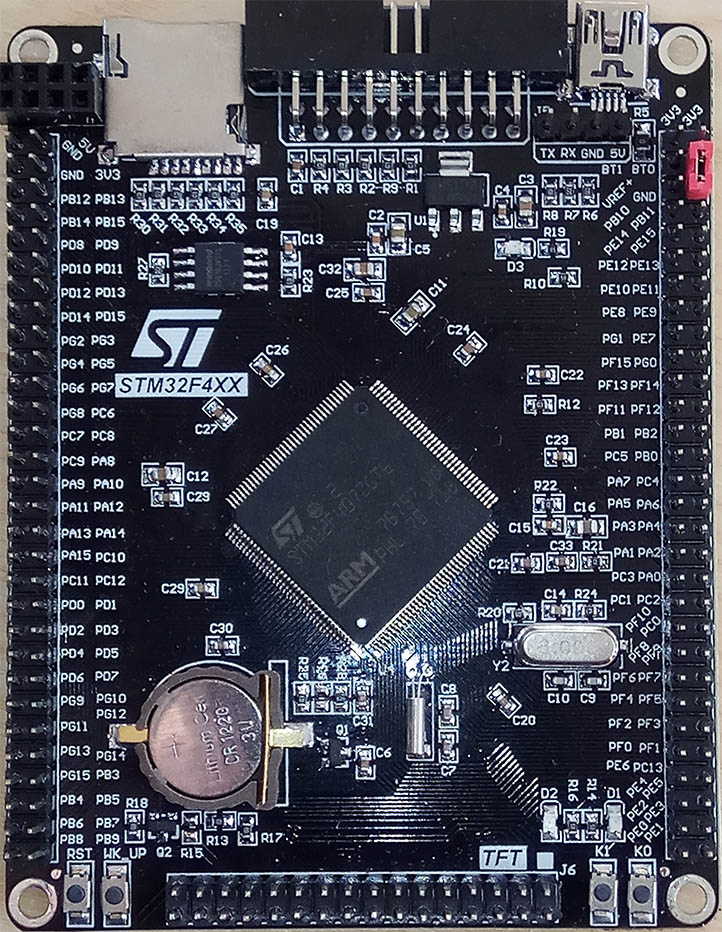
- f4.jpg (245.88 KiB) Viewed 284 times
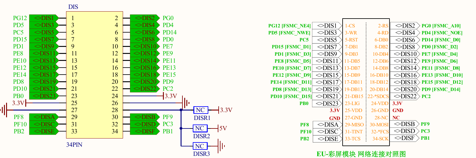
mad session of wiki file uploads, file names are either pretty good or mention the header numbers feel free
files with the name already up i didn’t replace i think.
—————–
well now! that’s a ZGT but the pcb is that of the ZET. connection wise – is it a drop-in replacement ![]()
i’ll check upgrade path in CubeMX, i wish they’d have run out of the zets faster ![]()
mine’s definitely a ZET ![]()
then i’m not surprised the schematic is a bit wacky, 8 pin 4×2 is for a nRF24, connections in schematic might be close though, avo time.
tft high address line used A6/A18/A?? there are some annotations on the display connector outline in the schematic, might also need the avo
do you still some extra pics ?
stephen
You connect that to JTAG header (between SD and USB) pins TMS(PA13)=SWDIO, TCK(PA14)=SWCLK, GND and 3.3V(Vref). That’s all.
i said BMP as OP wanted debug output.
rather than searching for the trace mod to an usb stick st-link, avoids f101/f103 issue as well.
also who hasn’t a spare BP to hand
407 ds doesn’t seem to care ZE v ZG
also
Full compatibility throughout the family

The STM32F405xx and STM32F407xx are part of the STM32F4 family. They are fully pin-

to-pin, software and feature compatible with the STM32F2xx devices, allowing the user to

try different memory densities, peripherals, and performances (FPU, higher frequency) for a

greater degree of freedom during the development cycle.

The STM32F405xx and STM32F407xx devices maintain a close compatibility with the

whole STM32F10xxx family. All functional pins are pin-to-pin compatible. The

STM32F405xx and STM32F407xx, however, are not drop-in replacements for the

STM32F10xxx devices: the two families do not have the same power scheme, and so their

power pins are different. Nonetheless, transition from the STM32F10xxx to the

STM32F40xxx family remains simple as only a few pins are impacted.

Figure 4, Figure 3, Figure 2, and Figure 1 give compatible board designs between the
[Nutsy – Sun Jan 21, 2018 3:06 pm] –
What about debugging? Can the stlink be used? i assume its not by the normal serial print?
OK, I understood that as “normal” debugging, and not debugging with serial print via STLink.
Yes, STLink can be used for debugging, but not sending serial printouts over STLink.


STLink can be used for debugging, but not sending serial printouts over STLink.
It sure can. With some stlink v1 and all v2 and later, you can use the virtual serial port over stlink to transmit data out to a host. I can post a link later.
This opens up a lot of opportunities, like visualization, …

Your VG is massive!
The eBay listing for my VG said it had on-board ST-Link but, of course, it hasn’t.
So I just connected ST-Link SWDIO / SWCLK to PA13 / PA14 and PA9 / PA10 to a separate FTDI and, to my surprise, it all worked (using Arduino IDE and generic F407 setting). A bit of a mess about, but a simple solution.
[Wolfie – Mon Jan 29, 2018 1:35 pm] –
Your VG is massive!
*blushes* why thank you…
oh and the massive board is a zgt, not a vgt or vet
yeah theres a few different versions going around. But good to know stlink works as it should… I might start playing with the board soon…
stephen
Ah yes, my mistake, but I’m not happy that your board is bigger than mine, I want a black zg too!
I think you’re right on both points. I hadn’t thought of it like that.


