A regular Uno shield knows where Analog# A0-A5 are and where digital 0-7 are.
The Maple and Nucleo boards have Shield connectors. Only the Nucleo has A0-A5 defined.
Most Arduino boards have their pin mapping in variants/VARIANT/pins_arduino.h (or variant.h)
Even the small boards like Nano and Pro Mini.
The Teensy boards have digital numbers and Analog numbers.
Most STM32 users seem to refer to pins by their portpin name e.g. PC15
And these can be mapped as enums.
Would it be possible to add some “official” A# style defines for the Maple? (which has shield headers)
Would it be wise to add some “official” A# style defines for the BluePill? (which has a consistent pin layout)
It would also mean that the new BluePill Adapter board will attract plug and go examples for popular Shields.
David.
Most boards are labelled with the official STM names for the pins e.g. PB5
The Maple mini just has pin numbers.
If there was a board which specifically had those pin names on its silkscreen, it would be possible to make a variant for that board, but we already have masses of variants and it would probably need to go into a special branch or possibly be added via a patch, rather than make the core even larger for a board which only 1 or 2 people own.
quote]
Would that actually matter?
Can we not decide on a standard mapping, possibly even based on the Nucleo as below where the blue pin names are what the arduino calls them and the blue numbers are the STM32 pin names and be bilableual (just made that name up) so if you used either A5 od PC0 in your code, both would be recognised?
I’d have to redesign my shield adapter but if it gave the blue pills etc, greater scope, c’est la vie!
btw, Ive put the current designs in a github (never had a git hub before, I’m so proud hehe) https://github.com/BaartCM/STM32_UNOShield
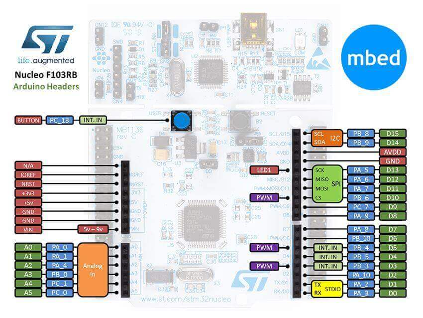
- nucleo_pinout_6.jpg (71.26 KiB) Viewed 1223 times
But, I still think that we could come up with a suitable mapping and you Roger, as the STM32Duino deity can ratify into divine law.
I cant remember if there are #defines in the variant file for the Nucleo F193RB, for the analog or digital pin numbers.
But if not, they could be added.
However for the BluePill etc, I think it could cause problems adding definitions which are not releated to what is written on the hardware.
I.e this change seem to relate to a converter shield for the BluePill, not to the BluePill on its own.
PS.
i dont have final say…
I changed something recently, to enable the SWD pins on all boards all of the time, as several people requested it, despite my misgivings about the change. Only to have a load of complains from other people as the change broke their existing projects.
So I had to remove that change and make those pins back into GPIO.
This strikes me as the same sort of thing. i.e. if a significant proportion of the userbase request this change, I could do it, but there are over 1000 forum members and hundreds of forks of the repo, plus hundreds of people who seem to communicate via youtube, all of whom may or may not want this change.
You didn’t deny being the diety though!
Its not exactly a change, more of an addition. Its just like being able to use NOT or !, interchangable numbering. Like
#define D1 0X00FF
#define PC13 0X00FF
you could use either D1 OR PC13 and get 255 (couldn’t you?)
Anyway, IF you could then here is my first design adapter board. It can be perered from the barrel socket ot either USB and I included the 2X22R resistors and the 1K5 resistor and connected the USB on the UNO board to D-/D+
Steve
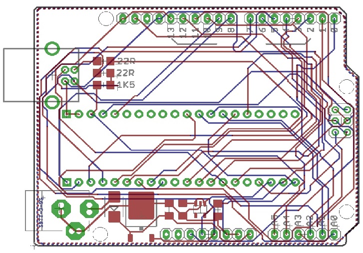
- stm32-UNO.jpg (196.46 KiB) Viewed 1190 times
Steve.
Edit …
In the ….hardware/STM32duino/STM32F1/variants/nucleo_f103rb/board there is a board.h file containing the pin definitions so it can be done whoop whoop.
If you weren’t a dude, I could kiss you!
I quite like the name neutrino too, its fitting and takes me back forty odd years listening to a band called Klatuu!
Steve
<…>
Would it be possible to add some “official” A# style defines for the Maple? (which has shield headers)
Would it be wise to add some “official” A# style defines for the BluePill? (which has a consistent pin layout)
It would also mean that the new BluePill Adapter board will attract plug and go examples for popular Shields.
David.
IMO, it is all about the Big Picture and the original intent of having a forum dedicated more to the advanced user and not the newbie for the 32-bit STM32Fxxx.
IMO, No newbies, no growth in the number of advanced users. And when the older farts like you and me die off, then what?
Steve.
The arduino.cc forum caters for 32 bit Atmel boards which by comparison to the stmf103 is slow. For this exact reason, I moved on from using UNO’s and MEGA2560’s to the blue pill, despite the dificulty of wiring stuff up to them compared to the aforementioned arduinos.
Where does one go to get in depth knowledge of programming the stm32f103 using the arduino IDE if not here.
I never considered this forum to be funded by any corporate organisation I alway thought it was set up by people who wanted to expand their own knowledge by sharing ideas etc and also to pass that knowledge on.
I myself am not deeply knowledgable about the internal workings of the stm32f103’s however, I’m more than capable of designing hardware to make using these devices easier and offering support to those who would make use of them.
I designed an adapter which would allow a blue pill to connect to the various UNO shields available including the many MCUFRIEND TFT shields. It also makes many of the pins available for use too and has many 3.3V, 5V and 0V pins to power sensors from its own power supply. I made the design of this shield available to all who want it. I’m not selling anything here, though I might offer a few on eBay as not everyone has the capability or desire to make their own. I sent David Prentice a board and blue pill as he told me he doesnt actually have a blue pill. He kindly modified his MCUFRIEND_kbv library so it will work with the stm32f103 and my adapter and he made it available on his github. His request at the top of this thread was for the benefit of other stm32duino users, not himself or me. I now have an adapter and working driver for the many TFT screens his drivers support. I’m a happy man. If nobody else wants to use my designs or David’s driver, I’ll still be a happy man. I tried to share.
One last comment, I have seen a few posts where you suggest Roger doesn’t have time and shouldn’t be wasting himself on a particular topic. Shouldn’t HE be the one to decide that?
This is my last post on the subject or we could go on for page after page.
However, if you want to print a rebuttal, then I will read it but not reply. Let’s get back to the work of making the stm32duino greater than it already is.
Steve.
Some wise thoughts.
Rather than try for perfect, it would be useful for some of us working on variants to contribute to the grand experiment that is STM32duino to be able to leverage some of the wisdom of those who have been there before. Roger’s earlier post on trying a new, and possibly improved, layout that broke existing code is a good case in point.
To nuts and bolts.
Stephen (@zmemw16) and I have been collaborating on a F4VET6 variant, primarily to take advantage of Frederic’s new “cube” code. Because our $15 “Black” boards have some onboard hardware (Flash, SDIO) a few of the choices have been made MCU on port/pin assignments. We also have around 90 header pins to play with on the VET6 boards and even more when we get on to the ZET6 variants.
http://wiki.stm32duino.com/index.php?title=STM32F407]
Which are the main things to keep standard across the STM32 variants?
Some of the tradeoffs we’re playing with:
If we try for Uno style digital pin numbers for key functions (e.g. MISO, MOSI, LED=D13…), then the header to digital pin mappings go crazy.
Where is it important to keep the base function ( e.g. SPI1, I2C1, UART1) available and mapped so that libraries designed for simpler chips work?
Are there some clever tricks that can allow us to have our cake and eat it? For instance Frederic mapped physical Uart6 back to a virtual uart3 in the initial cube code for code compatibility.
Any hints for us guys who are trying all this for the first time in STM/Arduino land?
Richard
If we try for Uno style digital pin numbers for key functions (e.g. MISO, MOSI, LED=D13…), then the header to digital pin mappings go crazy.
the sheer variety for stm32 alone with a large number of different pin layouts and mapping (some of them with arduino connectors)
http://www.ebay.com/sch/i.html?_from=R4 … 2&_sacat=0
i’d think makes it ‘impossible’ to define a ‘standard’ physical pin layout, or rather the STM’s definitions of PAn-P?n is probably a good reference.
and e.g this F407ZGT6 Demo Board http://www.stm32duino.com/viewtopic.php?f=39&t=1980 found by zmemw16 breaks out a large number of pins including the fsmc memory/lcd interface pins
and with breakout boards and sensors boards from adafruit (https://www.adafruit.com/category/42), sparkfun (https://www.sparkfun.com/categories/20) and many more variants/oems on ebay, aliexpress etc, basically leaves very little in common in this evolution
and in particular with things like the STM32F407{V,Z}* boards with a large number of pins broken out and in which the mcu has on board support for fast 100mbps ethernet (requires external RMII PHY) and high speed 200mbps usb 2.0 interfaces (requires external PHY), and with fsmc (we could put more sram if really needed), making use of all these pins fast ethernet, usb2.0 high speed, adding sram would launch into areas that ‘arduino uno pins’ has not reach prior. it would seem that this growth would take us further and further away from the modest beginnings of arduino uno. it is in fact a good thing (i’d not be surprised if one day we interface megapixels camera modules, hdmi etc)
that may lead to a some ‘old’ artforms coming back again in full swing e.g. *wire wrapping*
http://makezine.com/2009/07/27/lost-kno … -wrapping/
https://forum.arduino.cc/index.php?topic=62942.0
https://www.bigmessowires.com/bmow1/
i’m seeing it more possible to mix and match mcu boards with the breakouts and it is possible to build pretty functional devices connecting them via wire wraps etc, and they could stay fairly compact in a box as well that way
it seemed we are moving away from the days of ‘shields’
actually what this leaves us is that the basis would be based on a properly done schematic showing where which pin on the mcu goes to which other pin on the ‘header’. i.e. the schematic becomes part of the product for microcontroller boards
just 2 cents
Given that we’re moving away from shields, hats, cloaks and other fixed pinout arrangements, particularly for these more advanced boards, my main motivation is to make things easier for the developer to create software and hardware together.
I read DanielEff as proposing that we move away from the Dx notation in code, as it doesn’t translate physically at all well between boards. Either we get nonsensical physical pin numbering as the Uno default Dx pins are maintained, breaking any straightforward numbering scheme. He advocates simply going with PXNN – which I hear you supporting.
Frederic P seems to have come to the same conclusion, simply numbering the pins down the two inside rows and then the outside rows on the headers, where the board (e.g. Disco) doesn’t have a Uno-style header, and trying for Uno pin number compatibility where they do (Nucleo).
Of course, libraries that still have the Uno pin defaults embedded way down in the code will break. Probably not a big issue, merely tedious, for the kinds of developers attracted to these advanced boards.
Considering that ordering the PXNNs in the various enums and arrays that define PortToPin translations to follow the physical (pin header) layout costs nearly nothing, timewise, that is probably the way to go.
Custom hardware
Daniel’s STM32GENERIC implementation takes this further than Frederic’s by maintaining the AF options for each chip in the core code, e.g. STM32GENERIC\STM32\system\STM32F4\stm32_chip\stm32_STM32F407VE.h for that chip.
Frederic’s leaves these tables at the variant level.
Daniel’s basic choices about where to map pins were excellent (take the SPI1, SPI3 selections where many of the possible pins are available to either).
However, most of the advanced boards have some additional onboard hardware – e.g. the Black F4VET6 boards have SPI flash, SDIO socket, USB_OTG_FS and TX1 already allocated. Optional JTAG, Touch/TFT and NRF24L01 headers are also provided. This may mean that some of the options need to be changed. In Daniel’s implementation that means playing around with the stm32_STM32F407VE.h file or cloning it and then editing stm32_build_defines.h
Each approach has its benefits and costs when implementing new variants and developing projects.
We’re really lucky with the quality of support emerging for F4’s. Creating a few different variant files is a small price to pay!
Richard
i’ve taken a look at this
https://github.com/palmerr23/Black-F407 … PinNames.h
and this
https://github.com/palmerr23/Black-F407 … eralPins.c
i’d think it made a lot of sense for a developer working on the board as the pins are named PAnn – PZnn
and they are mapped nicely in PeripheralPins.c
as an example:
e.g. the analog pins are mapped nicely thought not necessarily in a strict 1 unit increment
analog pins
PA0, PA1, PA2, PA3, PB0, PB1 (and actually more is defined)- this would have given the same resources as an arduino uno board i.e. A1-A6
and this is going beyond the original arduino uno some pins are aliased so that if it is mapped for both analog and say another purpose say spi, it can only be used for either of analog or spi but not both. while in this case, it is a conflict free mapping (i’ve originally thought about using PA5-PA7 for SPI aliasing that with the analog pins, but now it becomes to possible to have both analog1-6 and SPI). imho we have achieved and gone beyond the original specs for arduino uno providing 6 analog pins (and we actually provide more)
similarly arduino uno offers an aliased SPI port (i.e. either gpio / analog or purpose specific), an aliased I2C port, an aliased UART port (RX, TX) , we’ve provided the same resources and are providing more than that and our ports are mostly mutually exclusive as like the adc pins above, we’ve gone beyond the arduino uno. (i.e. meeting the same resources as an arduino uno and actually offering more)
what it would take would be like providing a diagram showing the board layout in which we show the PAnn-PZnn assignments and their default configured functional mappings (e.g. ADC, SPI, I2C, UART, GPIO)
e.g.
http://www.stm32duino.com/viewtopic.php … 913#p25355
using PAnn – PZnn assignments would also help in cases where there are different f407{v,z}et boards where the header pin assignments are different
e.g. PA1 may be the first pin on the header on a particular board, but perhaps it is the 10th pin on another board
the peripheral would still work so long as they are connected to the pin with the same PAnn assignment even if they are literally different boards
i think this echos what danieleff has commented
of course this would break the concept of ‘shields’ even if the 2 different boards and connectors are identically dimensioned
but i’d guess it is fact of life, that’s the way it works
shields i’d think is a ‘hardware concept’, the hardware hence the board or shield is deliberately designed to fit the same PAnn header connectors
the truth is that rather often the same PAxx pins can be reconfigured to a different purpose, dependent on the mcu design of those PAxx pins
however, the implication of our default mappings we do today for the f407{v,z}et6_black may just become ‘set in stone’ if it do become popular and that shields for f407{v,z}et6_black start emerging
just 2 cents
However, most of the advanced boards have some additional onboard hardware – e.g. the Black F4VET6 boards have SPI flash, SDIO socket, USB_OTG_FS and TX1 already allocated. Optional JTAG, Touch/TFT and NRF24L01 headers are also provided. This may mean that some of the options need to be changed. In Daniel’s implementation that means playing around with the stm32_STM32F407VE.h file or cloning it and then editing stm32_build_defines.h
Looks like we’re all on the same page and working in parallel.
I’m just reworking my Black VET6 variant for the Cube / Maple to fit in with Daniel’s advice over the last few days.
I think I’ve now fixed on where the defaults should be, and a useful pin mapping.
I was about to ask you (Daniel) if we could change the Arduino style pin numbering to match the header layout. Pretty much all your other defaults work well.
The only change I’ve made to the schematic’s defaults is to assign SPI3 to the Flash/NRF headers, as this leaves SPI1 available for other purposes, with a full set of NSS pins for SPI-DMA use.
I’ve got the variant code for the the STD32duino core https://github.com/stm32duino/Arduino_Core_STM32F4 – I used to call it the “Cube” version, but yours is equally “cubed”! and have now updated my repo https://github.com/palmerr23/Black-F407VET6-cube with the files.
My logic is in the front worksheet in the Excel spreadsheet in /Documents.
Very happy to hear any suggestions for improvements!
I’ll work up a “STM32Generic” version over the next few days. I just want to make sure the peripheral default pins are correct.
As for a pretty pinmap – it’s on the way – once we’ve stabilised the pins!
Richard
Corrections gratefully accepted.
Richard
I still maintain that STM32 with Arduino Headers should have those pins mapped correctly.
e.g. Maple and Nucleo boards.
Yes, the BluePill, MapleMini, … have portpin names printed rather than any Arduino “digital number”
So it seems wise for the relevant variant.h to just map them in a logical way e.g. with the ordered enum list
In an ideal world, you could choose an Arduino-compatible mapping e.g. like LeafLabs or ST did.
However I don’t think that you can get an effective equivalence. And there would certainly be arguments about which was “best”.
I would suggest that variant.h should contain the “default” USART, SPI, I2C, … mapping for a variant.
The core Serial, SPI, … functions would know which USART, SPI registers to use. And whether any alternate function mapping is needed.
The MapleCore has facilities for alternate mapping and multiple peripherals. The ST core seems to only support a single SPI device at the moment.
Regarding any STM32 project development, the NUCLEO (and DISCOVERY) boards are well designed and convenient. Even if a finished design eventually runs on a custom pcb. And let’s face it. The STM32F4 and STM32L4 are superior to the F103. The STM32F0 is useful too.
David.
ARDUINO_ANALOG1 .. ARDUINO_ANALOG6
and this header can be grouped together with the sketch itself as part of the app, hence you could taylor the app to different boards by updating the mapping
however
– the pins on different boards would be at different physical locations assuming that ARDUINO_ANALOG1 – ARDUINO_ANALOG6 are mapped to the same PAxx pins. this defeats *shields*
– some of the same mcu PAxx pins may not be usable on a different board as they could be assigned for some other purpose, this means that alternative underlying PAxx pins need to be reassigned
– the same compiled binary cannot be used for 2 different boards, they *will not work* even if they have definitions of ARDUINO_ANALOG1 – ARDUINO_ANALOG6 as the underlying PAxx mcu pins are different. this means that you would need to compile from source against the headers for each and every different board even if the mcu is identical.
this literally describes the state of those ‘arduino uno connector’ pins, it may work on different boards with a similar looking connector if you rebuild the program from source and provide the alternate defines / mapping to the underlying mcu pins. and that’s provided you used it for the ‘simple’ purpose e.g. either only analog or gpio depending on those labels
– the aliasing of the arduino pins would be different dependent on the underlying PAXX pins assigned and on the underlying mcu, for example on one board arduino A1-A4 could have an alternate mapping as uart,
assuming you want to use arduino A1 analog pin and uart concurrently now you have a pin conflict, you would either need to use a different analog pin or not use the uart if you choose to remain as A1 for analog, and this can be different between 2 different boards for the *same* mcu and certainly different between 2 different mcu, even from the same manufacturer
In contrast, Freescale also provide sensible mapping on the FRDM boards. But the portpins are different on every board.
Personally, I have always thought that the “Shield” was partly responsible for the success of Arduino. It certainly makes prototyping easy.
Since ST make the chips and ST make the Nucleo boards, I would consider their mapping to be “official”. Of course this does not mean that everyone is happy with their choices.
It does mean that you have some form of “standard”.
David.
All true, and a useful summary of the duscussion.
There’s a concensus brewing that the Dx or Ax Arduino-style numbering is probably worth putting aside for these more advanced boards, as the folks who are programming them don’t need to be insulated from the actual ports/pins.
In fact it’s just another thing to remember. The most important thing is to provide a good set of default pins and some sensible alternates, so that libraries can check for “legal” pins without having to know too much about the hardware, particularly when trade-offs need to be made for particular hardware combinations.
There’s a few gotchas that will need more careful programming- to check combinations, not just pins are legitimate. For instance, on the STMF4 SPI1 and SPI3 can use almost identical pin sets. Thus the tables could contain duplicate port mappings, e.g. PA5, for two different SPIs. Choosing the first matching one would not necessarily be correct.
It’s all part of the fun !
You have certainly captured the early Arduino dream, which still lives on in the Uno and close derivatives. And they’re great for getting into embedded computing.
ST and some others have made Uno “compatible” boards for different CPUs, which has helped to strengthen the Arduino brand as simple and compatible.
Certainly, it makes sense to stay with the ST Nucleo mappings for Uno style layouts.
However, some of their choices don’t play out all that well when you’re trying to harness the full power of the more advanced chips. The Nucleo F4’s alternate headers are a good example – they make the full set of ports are available – more like 80 GPIOs compared to the Uno’s 18!
This doesn’t diminish many of the big Arduino advantages for most folks: the simplicity of the IDE – pre-defined (and invisible) makefiles, pre-built toolchains and lots of libraries that are relatively easy to adapt to new hardware. (Special thanks to Ada and Sparkfun.)
We’re all pretty passionate about evolving the Arduino standards in productive ways, to bring an ever wider set of hardware into the fold, to create the next generation of Arduino compatibles and to create some innovative projects along the way!
https://en.wikipedia.org/wiki/Nonblocki … ing_switch
there can be an include say in Arduino-Uno.h together with the sketch, for now this include would need to be part of the sketch or application
Switch 1: Arduino Uno to MCU pins mapping/translation
#define BOARD_LED_PIN PA6

#deifine ARD_UNO_ANALOG1  PA1

#deifine ARD_UNO_ANALOG2  PA3

#deifine ARD_UNO_ANALOG3  PA8

#deifine ARD_UNO_ANALOG4  PB1

#deifine ARD_UNO_ANALOG5  PB2

#deifine ARD_UNO_ANALOG6  PB5
#deifine ARD_UNO_DIGITAL1 PA10
#deifine ARD_UNO_DIGITAL2 PA11
etc.
And you have the enums in variant.h
Any Arduino initialises as a “bog-standard” e.g. PWM, millis(), …
with the pins in a known state.
And if you choose to do any remapping, this can be catered for too.
Yes, of course you can configure your own code exactly the same as on a Uno, Mega, Due, …
And you take responsibility for your actions. e.g. if you commandeer a Timer for your own purposes.
It just seems wise to provide a simple base-level Arduino compatibility. So that the standard Arduino examples work out of the box.
And standard or third party shields can just work.
What makes you think that Cortex-M0 chips do not have ADC ?
Yes, there are technical differences between M0, M3, M4 peripherals.
David.
the notion that ‘standard arduino shields’ would ‘just works’ needs to fit very restricted context
e.g. based on the arduino uno
– it needs to have arduino uno connectors, with specific exact matching dimensions
– it will be restricted to the arduino uno sub set, i.e. those analog pins will only be analog pins no aliasing of other pins on those same pnis
(alternate mapping may be impossible to be catered as the underlying mcu architecture is different
– it needs to have a led pin and at the identical mapping as arduino uno
– the digital pins will simply be gpio pins
– and the spi port will be a single spi port – no changes no reassignments whatsoever as the alternate of that spi is different across mcus and pin mappings
hence the above will only work and applies to ‘adruino uno’ compatible boards
as i mentioned at front, not all generic boards would fit the ‘arduino uno’ compatibility framework, some mcus simply don’t have analog pins (no adc)
some board don’t have a user led, hence you can’t blink that
and so call ‘fitting within’ arduino uno framework means restricting otherwise useful functionality on the other generic boards (e.g. configuring alternate functionality on those same pins, because the alternate functions are certainly not going to be the same even if the same connector is used)
and lets just say that we want ‘arduino uno’ compatibility across the broadest class of *any* known generic boards and mcu (be they nucleo boards, all the oem china generics, or just about any other generic cortex-m boards)
the only reasonable way to achieve that is that the sketch needs to do all that mapping to those specific boards to achieve the restricted arduino uno functionality fitting its restricted needs, i.e. analog a1 – a6 is strictly analog a1 – a6, spi is spi and so no alternate functions (no spi1, spi2, uart1, uart2, no ethernet etc) i.e. only that specific restricted subset is going to work, the sketch needs to know its board and mcu and do that mapping accordingly
and any way all the generic or any 3rd party board do not necessary provide an ‘arduino uno’ connector. hence all that ‘arduino uno’ shields is simply not going to fit anyway. except for those so specifically designed to fit arduino uno connectors
in short, arduino (uno) compatibility is the problem of the sketch, not variant.h as variant.h needs to cater to the optimum use of board resource and not restricting itself to the subset of arduino (uno), i.e. the sketch does it own mapping into the PAxx assignments defined by variant.h so that the sketch can always use is own restrictive arduino uno subset and mapping and view of the arduino uno world

