Is there a way to sync the timers? Using PWM I have trouble with one channel high side going up and the low on the other timer going out of phase, so it doesn’t move and than jumps when it matches! I bought a logic analyzer to test it but if anyone can help me I’ll be a very happy camper! I’ll post the 3 phase sine generator code as soon as I make it work!
The driver is IR2101S, and I’m using a 24khz PWM frequency
 HardwareTimer timer1(1);  timer1.setPeriod(40);

HardwareTimer timer4(4);  timer4.setPeriod(40);
https://electronics.stackexchange.com/q … -same-time
Other results: https://www.google.com/search?q=STM32F1 … ronization
Good luck,
Ray
TIMER1 channels both normal and negate signals are available on pins, check the pin mapping in the chip manual.
TIM1_CHx and TIM1_CHxN, wherein x = [1,2,3] == PA8,PA9,PA10 + PB13,PB14,PB15 (RM0008 p.178, Table 46).
Steve, 3*2 will not work to… if it’s out of sync when the 2 values start matching it will go at twice the rate and when they aren’t matching there will be no LOW and HIGH at the same time so the motor will not turn, and then the motor will jump between not on to 2x matching… I really need the 6 channels to run in sync!!!
Ray, thanks!!! That’s exactly what I need! The stm32duino has this:
void HardwareTimer::setMasterModeTrGo(uint32_t mode) {

this->dev->regs.bas->CR2 &= ~TIMER_CR2_MMS;

this->dev->regs.bas->CR2 |= mode;

}
You are well ahead of 90% of the members because you have a logic analyzer. ..
I’m off in defective SSD land on a new product delivered Friday – I do not do well when name brand companies pump junk through distributors such as NewEgg.
Anyway, were I doing what you are doing, I’d get out my Saleah and make it earn its keep. STM has a PDF or two on timers and several online sources may be of value:
https://www.google.com/search?q=stm32f1 … r+tutorial
Also Geoffrey Brown from Indiana U. has at least one STM32 PDF and also a github page full of STM32 resources… might be worth a diversion.
The STM32DUINO has its roots deeply in the Leaflabs Maple effort and those pages are still online & searchable (via Google):
Like this: stm32f103 timer synchronization site:leaflabs.com
And, there is that dreaded TechRefMan.
Good luck,
Ray
The step by step instruction is in RM0008 p.399 “Timer synchronization” -> “Using one timer to start another timer”.
Just try it and you will see it is not that bad to use low level code. The big issue is to first make clear what you exactly need ![]() .
.
Tomorrow the logic analyzer will arrive and then i’ll be able to test it precisely, I just found out the un-sync with a oscilloscope, I’ll look on the leaflabs and the stm32duino cores to try finding the how to’s!!!
I did a while ago fixed a SSD from OCZ… lord knows how but the atmel eeprom was corrupted, had tree ssd’s two working just cloned one to the other and it worked…
The ssd’s should have a diagnostic system… usually they have a RX TX pins but nothing useful for us mortals…
Again thanks for all!!!!!!!!
Here’s the code, it’s messy for now I put 3 arrays one for each fase… I’ll use only one with a 120 degree diference for each phase, I tought that the problem was there so i made the code as direct as possible… Only after all that I discovered that the problem was the un-sync timers! And the speed control etc. is just for testing! At least the hardware works perfectly ![]()
//INIT
const int8_t sineU[] = {
0,3,7,10,14,17,21,24,28,31,34,37,41,44,47,50,53,56,59,62,64,67,69,72,74,77,79,81,83,85,
87,88,90,91,93,94,95,96,97,98,98,99,99,99,99,99,99,99,99,99,98,98,97,96,95,94,93,91,90,88,
87,85,83,81,79,77,74,72,69,67,64,62,59,56,53,50,47,44,41,37,34,31,28,24,21,17,14,10,7,3,
0,-3,-7,-10,-14,-17,-21,-24,-28,-31,-34,-37,-41,-44,-47,-50,-53,-56,-59,-62,-64,-67,-69,-72,-74,-77,-79,-81,-83,-85,
-87,-88,-90,-91,-93,-94,-95,-96,-97,-98,-98,-99,-99,-99,-99,-99,-99,-99,-99,-99,-98,-98,-97,-96,-95,-94,-93,-91,-90,-88,
-87,-85,-83,-81,-79,-77,-74,-72,-69,-67,-64,-62,-59,-56,-53,-50,-47,-44,-41,-37,-34,-31,-28,-24,-21,-17,-14,-10,-7,-3};
const int8_t sineV[] = {
87,85,83,81,79,77,74,72,69,67,64,62,59,56,53,50,47,44,41,37,34,31,28,24,21,17,14,10,7,3,
0,-3,-7,-10,-14,-17,-21,-24,-28,-31,-34,-37,-41,-44,-47,-50,-53,-56,-59,-62,-64,-67,-69,-72,-74,-77,-79,-81,-83,-85,
-87,-88,-90,-91,-93,-94,-95,-96,-97,-98,-98,-99,-99,-99,-99,-99,-99,-99,-99,-99,-98,-98,-97,-96,-95,-94,-93,-91,-90,-88,
-87,-85,-83,-81,-79,-77,-74,-72,-69,-67,-64,-62,-59,-56,-53,-50,-47,-44,-41,-37,-34,-31,-28,-24,-21,-17,-14,-10,-7,-3,
0,3,7,10,14,17,21,24,28,31,34,37,41,44,47,50,53,56,59,62,64,67,69,72,74,77,79,81,83,85,
87,88,90,91,93,94,95,96,97,98,98,99,99,99,99,99,99,99,99,99,98,98,97,96,95,94,93,91,90,88};
const int8_t sineW[] = {
-87,-88,-90,-91,-93,-94,-95,-96,-97,-98,-98,-99,-99,-99,-99,-99,-99,-99,-99,-99,-98,-98,-97,-96,-95,-94,-93,-91,-90,-88,
-87,-85,-83,-81,-79,-77,-74,-72,-69,-67,-64,-62,-59,-56,-53,-50,-47,-44,-41,-37,-34,-31,-28,-24,-21,-17,-14,-10,-7,-3,
0,3,7,10,14,17,21,24,28,31,34,37,41,44,47,50,53,56,59,62,64,67,69,72,74,77,79,81,83,85,
87,88,90,91,93,94,95,96,97,98,98,99,99,99,99,99,99,99,99,99,98,98,97,96,95,94,93,91,90,88,
87,85,83,81,79,77,74,72,69,67,64,62,59,56,53,50,47,44,41,37,34,31,28,24,21,17,14,10,7,3,
0,-3,-7,-10,-14,-17,-21,-24,-28,-31,-34,-37,-41,-44,-47,-50,-53,-56,-59,-62,-64,-67,-69,-72,-74,-77,-79,-81,-83,-85};
//Motor
int32_t motorStep = 0, motorPhase = 0, motorStepTimer = 0;
byte NRD = 1;
int throttle = 0;
//Debounces
uint32_t encoderDebounce = 0, gearDebounce = 0;
//PIN ASSIGNMENT
#define UH PB9
#define UL PB8
#define VH PB7
#define VL PB6
#define WH PA10
#define WL PA9
#define REVERSESW PB1
#define DRIVESW PB0
//int UH = PB9, UL = PB8, VH = PB7, VL = PB6, WH = PA10, WL = PA9;
//int REVERSESW = PB1, DRIVESW = PB0;
//FLOATS AND OTHERS
int32_t kU = 0, kV = 0, kW = 0;
int16_t jU = 0, jV = 0, jW = 0, currentStep = 0, oldStep = 0;
//----------------------------------------------------------------------------------------------------------------------------------------------------------------------------------------------
void setup(){
//PINMODE
afio_cfg_debug_ports(AFIO_DEBUG_SW_ONLY);
adc_set_sample_rate(ADC1, ADC_SMPR_7_5); adc_set_sample_rate(ADC2, ADC_SMPR_7_5);
HardwareTimer timer1(1); timer1.setPeriod(40);
HardwareTimer timer4(4); timer4.setPeriod(40);
//Serial3.begin(200000);
pinMode(REVERSESW, INPUT_PULLUP); pinMode(DRIVESW, INPUT_PULLUP);
pinMode(UL, PWM); pinMode(VL, PWM); pinMode(WL, PWM); pwmWrite(UL,0); pwmWrite(VL,0); pwmWrite(WL,0);
pinMode(UH, PWM); pinMode(VH, PWM); pinMode(WH, PWM); pwmWrite(UH,0); pwmWrite(VH,0); pwmWrite(WH,0);
//Charge BOOTSTRAP
pwmWrite(UL,2880); pwmWrite(VL,2880); pwmWrite(WL,2880);
delay(50);
pwmWrite(UL,0); pwmWrite(VL,0); pwmWrite(WL,0);
motorSquare();
//Throttle
pinMode(PA0, INPUT_ANALOG); pinMode(PA2, INPUT_PULLUP); pinMode(PA7, INPUT_PULLUP);
} //--------------------------------------------------------------------------------------------------------------------------------------------------------------------------------------------
void loop(){
//Throttle
throttle = adc_read(ADC1, 0);
//if(throttle < 409){throttle = 0;}
//GEAR
//if(digitalRead(REVERSESW) == digitalRead(DRIVESW)){NRD = 2;}
//if(digitalRead(REVERSESW) == LOW){NRD = 1;} if(digitalRead(DRIVESW) == LOW){NRD = 3;}
//if(NRD == 2){throttle = 0;}
if(micros() - motorStepTimer > throttle*100){motorSine();}
} // VOID LOOP END --------------------------------------------------------------------------------------------------------------------------------------------------------------------------------------------
void motorSine(){
kU = (sineU[motorStep]*288)/10;
if(kU == 0){pwmWrite(UH,0); pwmWrite(UL,0);}
if(kU > 0){pwmWrite(UH,kU); pwmWrite(UL,0);}
if(kU < 0){kU = kU*-1; pwmWrite(UH,0); pwmWrite(UL,kU);}
kV = (sineV[motorStep]*288)/10;
if(kV == 0){pwmWrite(VH,0); pwmWrite(VL,0);}
if(kV > 0){pwmWrite(VH,kV); pwmWrite(VL,0);}
if(kV < 0){kV = kV*-1; pwmWrite(VH,0); pwmWrite(VL,kV);}
kW = (sineW[motorStep]*288)/10;
if(kW == 0){pwmWrite(WH,0); pwmWrite(WL,0);}
if(kW > 0){pwmWrite(WH,kW); pwmWrite(WL,0);}
if(kW < 0){kW = kW*-1; pwmWrite(WH,0); pwmWrite(WL,kW);}
motorStep++;
if(motorStep < 0){motorStep = 179;}
if(motorStep > 179){motorStep = 0;}
motorStepTimer = micros();
}
https://www.tinaja.com/magsn01.shtml
Ray
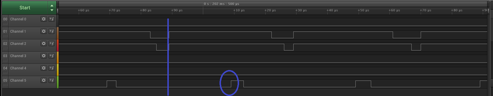
- un sync phase.png (33.13 KiB) Viewed 354 times
[mrburnette – Mon Aug 06, 2018 12:15 pm] –
It may be useful, if for no reason but a mental interlude, to review Don’s Magic Sinewaves:
https://www.tinaja.com/magsn01.shtml
Ray
Back in my 8051 assembly language days I wrote some code to make magic sinewaves for a 60hz inverter. It had a nice output but was hard to regulate to a precise voltage.
There are some good memories on the tinaja.com website. I still have a few original copies of his books on my shelf.
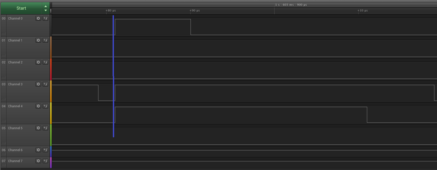
- sync phase.png (41.42 KiB) Viewed 326 times
Thanks….
TIMER1->regs.bas->CR1 |= 0x20;
[jdenis – Sat Aug 18, 2018 11:21 pm] –
Maybe it would be useful to put some of this commands on the PWM lib, to sync, center and other stuff that can be done!!!
Sounds like a plan…
What would you suggest ?

