
 The setup with stm32duino is easy and you don’t even need additional hardware (ST-link, Serial-USB converter…)
I think this is a really good board for greater projects and/or as main dev board.
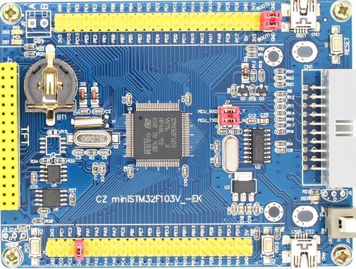
Key facts:
Price: about USD 10 —> http://www.aliexpress.com/item/FREE-SHI … 80157.html
MCU stm32F103VET6:
512kb Flash, 64kB RAM,
2 × 12-bit D/A converters
112 fast I/O ports
2 × I2C
5 USARTs
3 SPIs (18 Mbit/s), 2 with I2S interface multiplexed
32 kHz oscillator for RTC with calibration
Supports Compact Flash, SRAM, PSRAM, NOR and NAND memories
Board features:
all pin holders / rows already soldered
Boot0 and Boot1 jumper
jumpers (RX,TX) for the USB-Serial converter
2x USB one with CH340 RS232-USB-converter chip (“Serial1”)
32.768kHz and 8Mhz oscillators on board
CR1220 battery holder
reset button
Two user buttons: PD12, PC0
Two controllable LED; PE5, PE6
power indicator LED;
JTAG / SWD 20 -pin standard interface ;
32 foot FSMC TFT LCD screen interface
Board size : 101.5 mm x 76.68 mm
additional chips (already soldered)
SPI flash W25q16 (on SPI1: CS: PA4, MISO: PA6, MOSI: PA7, SCK: PA5)
EEPROM 24C02 (on I2C1: SCL: PB6, SDA: PB7 both with 4.7K pullup) IC Adress: 0x00 ( A0=A1=A2=GND)
space holder for 485 IC (PA3, PA0, PA2) and DS18B20 (Data: PB14)
Installation / preparation to use with STM32duino
Serial upload
Since the board has an USB-serial controller uploading is easy:
Install the CH340 drivers for your OS (google “CH340 arduino”) switch Boot0 jumper from GND to 3.3V, connect USB2 from board and use “serial upload” method. vola!
Drawback: for every upload you must switch the Boot0 jumper.
Bootloader upload
Sadly there is no ready made *.bin bootloader for this board (LED’s on PE5, PE6), but I already compiled one (see attachment). Set Boot0 to 3.3V connect it to USB2 and use the serial tool of your choice to upload the bootloader. After upload set Boot0 jumper back to GND and connect it via USB1 and use the board like your maple mini! Don’t forget to switch in the arduino IDE the upload method to “bootloader”! Benefits: You have a second serial-usb port (Serial1/USB2) so if you plan to do other USB things like mass storage, MIDI-USB you always have a debug option on serial1 !
additonals documents (attachment)
a) a schematic I found for this board (warning: usb-serial converter chip is different, but MCU pins are the same)
b) the new bootloader
Todo:
Code example and libraries for SPI flash W25q16 and EEPROM 24C02
edit:
I see Roger posted about this board, but maybe this topic is a good summery with additional infos (bootloader, schematics…)
The bootloader bin file in the attachment is named as “***pa9” but it’s really “***pe5”, so don’t get confused (will update it later)
Thanks for sharing the details. It looks like a great board.
Can you post the bootloader config.h and makefile with your changes, and I’ll update the repo and also build a bin and put it in the binaries folder.
Thanks
Roger
Roger, I thought you own this board already?
Can you post the bootloader config.h and makefile with your changes, Bit 7 Bit 6 Bit 5 Bit 4 Bit 3 Bit 2 Bit 1 Bit 0
1 0 1 0 A2 A1 A0 R/W
warning so far i’ve only seen the zet variant of this board on ebay or ali-express that doesn’t the eeprom or spi flash
stephen
Matthias
I have a VET and. ZET board, but they are much smaller, and only have 1 LED, which I don’t think can be on the same pin as your boards.
I will make a new generic board at the weekend, with an LED on PE5, which pin do you want the button to be attached to ?
Bit 7 Bit 6 Bit 5 Bit 4 Bit 3 Bit 2 Bit 1 Bit 0
1 0 1 0 A2 A1 A0 R/W
warning so far i’ve only seen the zet variant of this board on ebay or ali-express that doesn’t the eeprom or spi flash
stephen
All I can say is, that this board is really good designed “under the hood” (like 2 diodes for the battery, superb jumper positions…) . For USD10 its a real bargain for all those features.
Edit: Victor: You got exactly the same as mine!
generic_boot20_pe5
Button is on PD2
Maybe we should give our similar board names?
This board is called “Beauty Betty Blue”
Maybe we should give our similar board names?
This board is called “Beauty Betty Blue”
All I can say is, that this board is really good designed “under the hood” (like 2 diodes for the battery, superb jumper positions…) . For USD10 its a real bargain for all those features.
Edit: Victor: You got exactly the same as mine!
All must be reduced to acronyms! Maybe B-cubed? Or, BBB, 3B, or B^3
Be careful, Ray, BBB is already an acronym for Beagle Board Black, (and since few days, there is BBG for Beagle Board Green) …

Yea…
… Guess selecting acronyms follow the old adage, “If you snooze, you lose!”

Ray
“AVTduino“
“The device specially recommended users AVTduino”
That’s a new one (“duino”) for me… but an interesting board with the onboard Ethernet. The PDF was dated 5/2012
A search of github showed nothing for ‘AVTduino’, however. Vaporware? (or, maybe intended for the MApleIDE?)
Ray
I believe is not intended to even work with Maple. The usb port is connected to an usb-serial converter, so doesn’t use DFU, only the rom serial bootloader.
I think their intention is to just provide an STM32F1 board, and users need to find their own IDE and libraries.
I posted to “Don’t buy this board” and then! found this thread.
I have this exact ( pictured ) board, really needed this information, and could not get anything.
So,
(1) Has anyone found a exact plugin LCD for it?
(2) I am very much a victim of SSTM (senior short term memory) and the dreaded TMT (too many toys)
but if there are other neat things that need testing please let me know.
Many thanks for this info,
Bert
(1) Has anyone found a exact plugin LCD for it?
(is it worth starting a lcd connectors thread under hardware?)
http://www.aliexpress.com/store/product … 38181.html
http://www.aliexpress.com/item/2-8-TFT- … 38181.html
btw demo photo shows controller as an ILI9320
i’ve just spotted that the lcd’s are ‘sockets’ , that the zet6 boards, which i thought were identical
are different : J5(32 way) is a pin header on one and a socket on the other and the silk screen
pin descriptions for J5 are the same
these boards are 5 volts(J2) only
stephen
Bit 7 Bit 6 Bit 5 Bit 4 Bit 3 Bit 2 Bit 1 Bit 0
1 0 1 0 A2 A1 A0 R/W
warning so far i’ve only seen the zet variant of this board on ebay or ali-express that doesn’t the eeprom or spi flash
stephen
?? means a ‘something’
i’m not sure. i am aware that there may well be male and female connector versions of the 34 pin variety,
so far for lcd pinouts, i’ve seen lots! try a google images search.
also that they’ll most likely be yellow. also make sure they’re not shields, if unclear query the store??
does simplify there wiring though.
libraries, possibly 2 or 3 ….
i’ve finally sussed is that the display ‘module’ is really just 3 interface blocks on a single pcb and not one;
1. spi sd
2. spi touch
3. spi [edit]display interface with a data 8080/6800 micro type interface [/edit], just an extended hd44780 interface. someone will
no doubt tell me this can be connected/seen as an ‘spi’ type interface. is it ‘a’ or ‘an’, ‘an’ if subject first letter is a vowel??
i’ve been looking at the FSMC with CubeMX, frankly it’s a bit confusing and that’s without generating code..
there appear to be basically four(?) blocks, each with a selectable cs pin, each block can be a lcd or nand or ram or ….(4 or 5 options with right click);
it’s a lot of permutations for someone to use.
so unless it’s stated that in ‘our’ world block 0 will be sram, blk 1 flash, blk 2 is nand and blk3 is lcd, that middle layer HAL glue code is not going to be nice at all. ok – it’s somehow or will be an object with n types of behaviour/interface/parentage, missed that lesson.
this is also a problem with a physical board, how do you determine what each block is actually used for, put a led on the device cs and toggle?
yeah, probably; just a lot of v and z series boards out there – i’ve got at least 4/6/8 any of the ‘r’s??
c/v/z how many pins for mcu 48/64/??/???, next is a ‘level’ for functionality(8/b/e) and next is how the package is packaged(t=tray??)
also whilst the fsmc pins are nice and sequentially named in the circuit diagram, the physical pins had a bad hair day – all over the place.
stephen
what it means is it has a touch screen ic prob either xptnnnn or an adnnnn, both are common
and the display driver is either an ILI9325 or an ILI9328
you’re pretty unlikely to actually damage the chip if you try both drivers
hth
stephen
I have tried but not succeed
by the way which driver chip exactly this lcd used ?
http://www.waveshare.com/wiki/File:3.2i … -C-Code.7z
They provides code with both method by using Normal IO and with FSMC.
I do not know the FSMC more so I unable to configure it
In Normal IO method my board layout uses different pin configuration then code provided. I try to change pin config but unable to get success.
my stm32 board uses PortD amd PortE pins for LCD Data
I’ve a similar display but still have not gotten it to work yet …
http://wiki.stm32duino.com/index.php?ti … 2F103V_-EK
Edit.
The top 20 posters to this forum have been added as editors to the wiki, just do a password reset request with your login and you should get sent an email with instructions on how to reset / assign a password
Hope its is not OT:
– I am also using the Board described here and have started to work with it (have first loaded the STM32duino bootloader as described)
– have set the board type in Arduino as ‘Platine: “Generic STM32F103V series”‘ and as ‘Variant: “STM32F103VE”‘
– then done a small sketch which prints “Hello Worldx” on all five UARTS (x is the number of the serial port)
– in the code Serial1.begin to Serial3.begin is printed in red, Serial4.begin and Serial5.begin in black (unknown???).
– Compiling shows no errors
– the first three Uarts print ‘HelloWorldx’ as expected, Uart4TX and Uart5TX print ‘Hello World1’
(- I have additionally done Serial.begin(9600) and Serial.Println(“Hello World”) and the USB prints “Hello World” as expected)
Any idea how to use the whole five UARTS?
Regards, Jörg.
PS: I have added STM32 Support like described by RogerClark somewhere under ‘Installation on Windows.
PPS: seems I am stupid! After restarting everything and compiling and downloading everything works. I think I might have forgotten to set the variant correctly in the previous attempt? Sorry for the mess …
The first 3 UARTS are USARTS the last 2 are UART (No Synchronous transmission)
I remember having to change some code to make the last 2 serial channels work because they are subtly different
I thought I had tested it… However there are so many board variants I could have easily missed something
Everything is working for me now.
There is just one little thing and that is that the Serial4 and Serial5 keywords in the code (Arduino editor) are black and not red. Is this something that can be solved with some settings in the board files easily?
BR, Jörg.
Ummm
As Serial is a built in function (not a library), I don’t know of a way to make them get color coded correctly.
Its probably something that would need to be posted as an issue with the Arduino IDE
(though someone may correct me) 
https://github.com/arduino/Arduino/blob … ywords.txt
[Edit] Not just probably. Actually. I changed the file and recompiled the arduino java IDE and it worked.$ git diff
diff --git a/build/shared/lib/keywords.txt b/build/shared/lib/keywords.txt
index a89b7a1..ecb7768 100644
--- a/build/shared/lib/keywords.txt
+++ b/build/shared/lib/keywords.txt
@@ -180,6 +180,8 @@ Serial KEYWORD1 Serial DATA_TYPE
Serial1 KEYWORD1 Serial DATA_TYPE
Serial2 KEYWORD1 Serial DATA_TYPE
Serial3 KEYWORD1 Serial DATA_TYPE
+Serial4 KEYWORD1 Serial DATA_TYPE
+Serial5 KEYWORD1 Serial DATA_TYPE
SerialUSB KEYWORD1 Serial DATA_TYPE
begin KEYWORD2 Serial_Begin
end KEYWORD2 Serial_End
$
Did your fork the IDE on github or are you making local changes? (Actually, Can you easily send them a PR ?)
Thanks
$ cat FatSerial/keywords.txt
#######################################

# Syntax Coloring Map Servo

#######################################
#######################################
# Datatypes (KEYWORD1)
#######################################
Serial4 KEYWORD1 Serial
Serial5 KEYWORD1 Serial
Thank you very much. It is just a small detail, but very ‘nice to have’.
BR, Jörg.
Can I add this to the repo?
Can I add this to the repo?
I will see if I can do it this morning before heading over to Maker Faire
Todo:
Code example and libraries for SPI flash W25q16 and EEPROM 24C02
For I2C EEPROM : http://github.com/JChristensen/extEEPROM
For I2C EEPROM : http://github.com/JChristensen/extEEPROM
(I’ve used them since awhile, but I don’t remember if I had to tweak them and how, it should be pretty easy)
The SPI flash its SPIFlash.cpp:60:11: error: ‘SPSR’ was not declared in this scope _SPSR = SPSR;
TA
M
viewtopic.php?f=13&t=9&p=10&hilit=winbond#p10
All you have to do is to change in the examples every
if(mem.begin(_W25Q64,SPI,10))
to W24Q16 (if it is a library example)
As I remember in the zip folder there are some example with and without library, but this should be easy.
For the I2c EEPROM I took any of the standard libraries for Arduino (Or did I wrote it myself from the datasheet? – can’t remember) – so every “standard” I2c driven library should work. But you managed it already.
The SPI flash its SPIFlash.cpp:60:11: error: ‘SPSR’ was not declared in this scope _SPSR = SPSR;
The SPI flash its SPIFlash.cpp:60:11: error: ‘SPSR’ was not declared in this scope _SPSR = SPSR;
Here are two of the latest examples I found: One with the use of the library and the other one without
Keep in mind you have to erase one sector before you can overwrite it. (Maybe you can read my infos (german))
Example with library:
// ACHTUNG!!!! Immer zuerst den zu schreibenden Bereich vorher löschen, sonst Mist!!!!!

// löschen nur in Sektoren (4KB = 4096) möglich. d.h. immer 4096 Schritte einplanen oder zwischenpuffern

// Workaround: zuerst den Bereich, den man füllen möchte, mit 0xFF überschreiben? nicht geklappt
#include <SPI.h>
//#include <Metro.h>
#include "winbondflash.h"
winbondFlashSPI mem;
void setup()
{
pinMode(10,OUTPUT);
SPI.begin();
SPI.setBitOrder(MSBFIRST);
SPI.setClockDivider(SPI_CLOCK_DIV2);
SPI.setDataMode(SPI_MODE0);
Serial.begin(9600);
Serial.println("InitWaitingChip...");
delay(2000);
Serial.println("Init Chip...");
if(mem.begin(_W25Q64,SPI,10))
Serial.println("OK");
else
{
Serial.println("FAILED");
while(1);
}
}
void loop()
{
if(Serial.available() > 0)
{
switch(Serial.read())
{
case 'R':
{
//R0,100
Serial.print(F("Read "));
int addr = Serial.parseInt();
int len = Serial.parseInt();
Serial.print(F("addr=0x"));
Serial.print(addr>>8,HEX);
Serial.print(addr,HEX);
Serial.print(F(",len=0x"));
Serial.print(len>>8,HEX);
Serial.print(len,HEX);
Serial.println(F(":"));
uint8_t *buf = new uint8_t[len];
while(mem.busy());
mem.read(addr,buf,len);
for(int i = 0;i < len; i++)
{
Serial.print((char)buf[i]);
}
Serial.println();
Serial.println(F("OK"));
delete [] buf;
}
break;
case 'W':
{
//W0,test string[LF]
//
Serial.print(F("Write "));
int addr = Serial.parseInt();
Serial.print(F("0x"));
Serial.print(addr>>8,HEX);
Serial.print(addr,HEX);
Serial.read();
uint8_t buf[256];
memset(buf,0,256);
uint8_t len = Serial.readBytesUntil('\n',(char*)buf,256);
Serial.print(F(",0x"));
Serial.print(len>>8,HEX);
Serial.print(len,HEX);
Serial.print(F(": "));
while(mem.busy());
mem.WE();
mem.writePage(addr,buf);
Serial.println(F("OK"));
}
break;
case 'E':
while(Serial.available() < 1);
char x = Serial.read();
//Serial.print(x);
switch(x)
{
int addr;
case 'S':
Serial.print(F("Erase Sector "));
addr = Serial.parseInt();
Serial.print(F("addr=0x"));
Serial.print(addr>>8,HEX);
Serial.print(addr,HEX);
Serial.print(F(": "));
mem.WE();
mem.eraseSector(addr);
Serial.println("OK");
break;
case 'b':
Serial.print(F("Erase 32k Block "));
addr = Serial.parseInt();
Serial.print(F("addr=0x"));
Serial.print(addr>>8,HEX);
Serial.print(addr,HEX);
Serial.print(F(": "));
mem.WE();
mem.erase32kBlock(addr);
Serial.println("OK");
break;
case 'B':
Serial.print(F("Erase 64k Block "));
addr = Serial.parseInt();
Serial.print(F("addr=0x"));
Serial.print(addr>>8,HEX);
Serial.print(addr,HEX);
Serial.print(F(": "));
mem.WE();
mem.erase64kBlock(addr);
Serial.println("OK");
break;
case 'A':
while(mem.busy());
mem.WE();
mem.eraseAll();
long ss = millis();
while(mem.busy())
{
Serial.print(millis()-ss);
delay(1000);
}
break;
}
/*
if(Serial.read() == 'S')
{
//ES0
Serial.print(F("Erase Sector "));
int addr = Serial.parseInt();
Serial.print(F("addr=0x"));
Serial.print(addr>>8,HEX);
Serial.print(addr,HEX);
Serial.print(F(": "));
mem.WE();
mem.eraseSector(addr);
Serial.println("OK");
}
break;
*/
}
}
}
I was excited about this board, cause it seems to be versatile and it seemed to meet my requirements for a daily development device for testing purposes and so on…
I ordered it on aliexpress (9€) but what finally I got yesterday looks a little different but not so bad at all:
(If not already known here in the forum …)
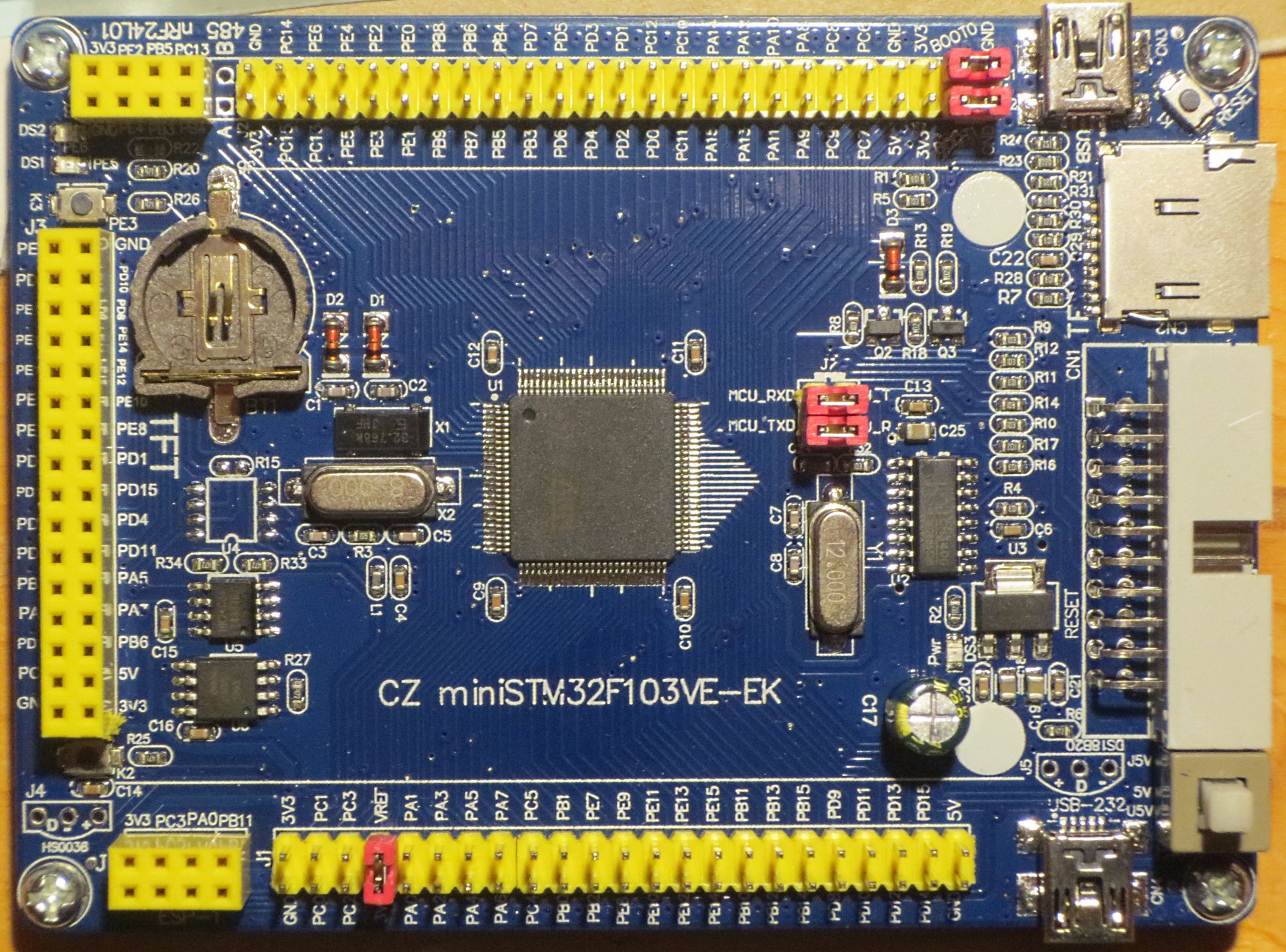
you can see that compared to madias board is has some new/different features:
- different name: CZ miniSTM32F103VE-EK (instead of CZ miniSTM32F103V_-EK)

- additional SD-Card Reader

- additional socket for ESP-01 Wifi-Module
- additional socket for nRF24L01-Module (2.4GHz ISM Transceiver)
- two user buttons on different ports now: PE3, PC5 (moved as well to different locations now)
- a more ‘modern’ RTC-crystal in plastic SMD package
- different serial I²C EEPROM 24C04 (512 Byte) (instead of 24C02)
- different / smaller RS485 connector space holder
- no inner mounting holes
- slightly larger Board size : 104.7 mm x 76.8 mm (instead of 101.5 mm x 76.68 mm)
the rest of the board seems to be the same:
- MCU: STM32F103VET6
- power on/off switch
- reset button (moved to different location now)
- Boot0 and Boot1 jumper
- jumpers (RX,TX) for the USB-Serial converter
- VREF jumper
- 2x USB one with CH340 RS232-USB-converter chip (“Serial1”)
- 32.768kHz and 8Mhz crystals on board
- CR1220 battery holder
- Two controllable LED: PE5, PE6
- power indicator LED (moved to slightly different location now)
- JTAG / SWD 20 -pin standard interface
- 32 foot FSMC TFT LCD screen interface
- SPI flash W25q16
- space holder for 485 IC
- space holder for DS18B20 (moved to slightly different location now)
- space holder for HS0038
i have the one in the image, x3 actually
if you look back in the thread there are details of the esp8266 and nrf24 connectors
i’m still trying ‘drive’ these boards
i also have the zet variant, all of tft, nrf24 & esp8266 as well
stephen
[zmemw16 – Wed Jan 03, 2018 5:08 pm] – if you look back in the thread there are details of the esp8266 and nrf24 connectors
could not find it in this thread, can you post a link please.
[zmemw16 – Wed Jan 03, 2018 5:08 pm] – i also have the zet variant, all of tft, nrf24 & esp8266 as well
do you have a picture of the ‘zet’ variant ?
viewtopic.php?f=28&t=2913&hilit=esp8266
this one starts at the pictures i posted
viewtopic.php?f=28&t=2913&hilit=esp8266#p37809
the details just happen to be still in my Notes app
ESP-1 WIFI module

Pin PC3 --- Reset

Pin PA0 --- CH_PD

Pin PB11 --- ESP RX

Pin PB10 --- ESP TX

Pin PC1 --- GPIO 0

Pin PC0 --- GPIO 2
NRF24L01 wireless module
Pin PE2
Pin PB5
Pin PC13
Pin PE4
Pin PB3
Pin PB4
[BlackBrix – Wed Jan 03, 2018 4:36 pm] –
I was excited about this board, cause it seems to be versatile and it seemed to meet my requirements for a daily development device for testing purposes and so on…I ordered it on aliexpress (9€) but what finally I got yesterday looks a little different but not so bad at all:
I got the same board in your picture, the one with the SD card slot, and the ESP8266 connector.
You say:
different serial I²C EEPROM 24C04 (512 Byte) (instead of 24C02)
Do you know what the I2C address for the EEPROM? Is it 0x50, 0x57, or something else?
Did you use a certain library for that EEPROM to work?
Another issue is that I can flash the bootloader using a USB to TTL converter, but even after I do this, I can’t use the mini USB cable to flash sketches. It works fine on the Blue Pill.
Still no solution to using the bootloader with the USB cable so far.
I used the I2C scanner from the examples, and there are two devices, one at 0x50 (the EEPROM), and another at 0x51 (not sure what that is).
I was able to write the to EEPROM using some Arduino examples. The EEPROM is only 512 bytes long, and the MSB/LSB code in the examples does not work for some reason.
Another question, did you try the SD card? I assume it is SPI connected.
If you have a 24c16 for example then you see devices 0x50 to 0x57
See here for an example of how this looks -> http://stm32duino.com/viewtopic.php?f=4 … 2&start=20
Furthermore, as I recall devices larger than a 24c16 (24c32, 24c64 etc) behave differently.
The board has a single 24C04, so only 512 bytes of EEPROM.
Initially I thought I would get the onboard EEPROM working, while I wait for a DS3231 RTC that I have on order. This has an onboard 24C32 (4096 bytes), and there are libraries for that that do work.
Of note is that you, like me, commented out the << and && lines for MSB and LSB to get the small EEPROMs working.
I wasted a couple of hours yesterday before I figured out that part. And the code is not portable easily between the smaller EEPROMs and the larger ones. So I guess it is best to wait.
Tried a couple of examples in the well written SdFat library, which supports SPI on STM32.
Whether I set SPI CS to SS pin or SS1 pin, it does not work.
try ‘cz 2018’ as a search.
you might want to check if it’s a non-spi version, forgotten the name, sdio ?
hopefully someone has a new schematic ?
stephen