Hello everyone,
I’ve started off using Arduino Nanos and built a couple little projects. One is a power meter for the house mains. It is based off of the OpenEnergyMonitor project. Works pretty good, but just not the resolution I need/want.
I’ve started off using Arduino Nanos and built a couple little projects. One is a power meter for the house mains. It is based off of the OpenEnergyMonitor project. Works pretty good, but just not the resolution I need/want.
So I got some STM32F103C8T6 boards. Here are the ones I got: ebay.com/itm/323591665224
moderator edit, seller relisted as
https://www.ebay.com/itm/STM32F103C8T6- … 3632180484
I would like to use one of these to upgrade the Energy Monitor project to a faster and greater resolution.
My current problem is that I can’t seem to flash it with anything “other” than the firmware that came with the boards. I used the STM Demonstrator GUI program to pull a good copy of the firmware off the boards. I use this to reflash the boards if something doesn’t work (which is 100% atm). The default firmware will bootup and flash PC13 at about 1000ms.
I have tried flashing:
generic_boot20_pb12.bin
generic_boot20_pc13.bin
generic_boot20_pc13_fastboot.bin
maple_mini_boot20.bin
All of which do not show up when I connect via the USB cable. I know the cable works as it works just fine with several other devices (cell phones, tablets, etc). The only way I can flash is using an FTDI232 board. I have even tried compiling the Arduino blink and then using the Demonstrator to upload the bin file, and it still didn’t blink.
Here’s the code I’m using:
int pins[] = {PC13, PC14, PC15};
// the setup function runs once when you press reset or power the board
void setup() {
// initialize digital pin PB1 as an output.
for (int i = 0; i < 3; i++)
{
pinMode(pins[i], OUTPUT);
}
}
// the loop function runs over and over again forever
void loop() {
for (int i = 0; i < 3; i++)
{
digitalWrite(pins[i], HIGH);
}
delay(500); // wait for a second
for (int i = 0; i < 3; i++)
{
digitalWrite(pins[i], LOW);
}
delay(500); // wait for a second
}
Go here: http://wiki.stm32duino.com/index.php?title=Main_Page
Read:
- Installation
- Bootloader
- Uploading a sketch
With Windows, you must install drivers: http://wiki.stm32duino.com/index.php?ti … stallation
[Korishan – Sun Dec 23, 2018 9:39 pm] –
mrburnette: I did that, all of those steps. Nothing’s working. That’s why I’m here
OK.
What I can tell you that the procedures work for 99% of the forum members. This leads us to Blue Pill users on Windows 10 Pro who are having similar issues… which breaks down into bad hardware, wrong/overwritten bootloaders, bad cables (try another), of a non-standard Windows installation or other Win issues such as premissions, relocated directories, failed IDE installs, etc.
Maybe Google using this criterion:
blue pill download problems site:stm32duino.com
You have not given much information with which to work. You may have destroyed the bootloader by uploading the .bin file; you could try a serial interface. ArduinoIDE generally expects to be used with the bootloader. Serial upload or ST Link overwrite the bootloader. Of course, you already read that here: http://wiki.stm32duino.com/index.php?ti … g_a_sketch
Ray
I have used both Arduino IDE and the STM Demonstrator Flash program, a separate USB cable, tried to get the resistor value down to 1.5k for USB interface. I’m using an FTDI232 interface, which works. The Demonstrator program will talk to the board and get the stats of the board just fine, this is not saying there is still something wrong with the board but this does show that the FTDI and the USB cable are working to talk to the board.
I haven’t given much info because I don’t know “what” to give. I have told you exactly what I have done, and exactly what the results are. I haven’t tried any other methods as I don’t ‘know’ what other method to try.
Images of Flashing using Demonstrator
Even after the “successful” uploads, when I plug in the usb directly to the stm32 board, I get the unknown device, which is also in the image. Also, the code does not run in either connected to the usb directly, or connected through the ftdi connection.
Are these boards dead? If so, why do they seem to take a flash, but then won’t run it? I don’t get that. Do I need to contact the seller and tell them all 5 of the boards I received are dead?
[Korishan – Sun Dec 23, 2018 11:40 pm] –
… exactly what I have done, and exactly what the results are. I haven’t tried any other methods as I don’t ‘know’ what other method to try.Images of Flashing using Demonstrator
Even after the “successful” uploads, when I plug in the usb directly to the stm32 board, I get the unknown device, which is also in the image. Also, the code does not run in either connected to the usb directly, or connected through the ftdi connection.
Are these boards dead? If so, why do they seem to take a flash, but then won’t run it? I don’t get that. Do I need to contact the seller and tell them all 5 of the boards I received are dead?
Most boards have a Blink sketch but few have a DFU bootloader; exception Maple Mini.
So, I keep pointing you to the WiKi references but I guess I need to explain a bit more.
You can only use DFU if there is a bootloader installed: http://wiki.stm32duino.com/index.php?ti … bootloader
It is the bootloader that supports DFU. No bootloader or corrupted bootloader, no DFU.
But, Windows must have a driver successfully installed for DFU to enumerate over USB. Windows users often have driver install issues… 2 or 3 failures per month, I guess. You can use forum or Google search to read these posts.
Upload via STM32duino bootloader
First, you need to ensure you have the drivers for the Serial and DFU (upload) devices installed — see Installation for instructions.
Also, your STM32 board needs to have the STM32dunio bootloader — see Burning the bootloader.
If your board does not yet have a sketch running, it appears as a Maple DFU device. This will be used to upload the first sketch.
Once a sketch is running, the DFU is not present, but the Maple Serial device is. Select its COM port from the Tools -> Port menu.
Both serial upload and ST-Link overwrite the bootloader… bye bye bootloader.
You purchased a cheap piece of hardware. You modified the board to use the USB enumeration. You used a utility to create a backup and it “appears” to me you used the utility to re-flash the uC. That is not something I can address … your bootloader+sketch may or may not have been successfully replaced… or you may never have had abootloader!
I suggest:
Try to (re)install the DFU bootloader using the above link.
-OR-
Load the bootloader 2.0 sketch using serial/STLINK and let the sketch burn a good bootloader copy.
Good luck,
Ray
Check again the USB pin soldering, and re-solder them if needed.
I suggest to use STLink for upload (set it in Arduino IDE) and try the blinky sketch.
PC14/15 is bad to use because the 32kHz xtal (for RTC) is mounted on those pins. Use only PC13.
1. Enable the native bootloader by setting Boot0=1 and Boot1=0.
2. Connect your USB/Serial adapter to pins PA9, PA10, GND, and 3.3V.
3. Flash this bootloader using the ST demonstrator GUI: https://github.com/rogerclarkmelbourne/ … 0_pc13.bin
4. Set both boot jumpers = 0. This enables the board to run the new bootloader that you just uploaded.
5. Use a USB cable to connect to your computer. Press reset on your board. You should see the LED blink rapidly for about a second followed by about 5 slower blinks for another second.
6. Check device manager. You should see a new USB Serial device in “Ports and LPT.”
7. Use PuTTY or another terminal program to connect to the serial device noted in step 6. The default serial settings (baud rate, etc) for PuTTY are ok but you will need to change the COM port to match device manager.
Verify that you see this message repeating about every second on the PuTTY screen:
Congratulations, you have installed the STM32duino bootloader

See https://github.com/rogerclarkmelbourne/STM32duino-bootloader
For more information about Arduino on STM32

and http://www.stm32duino.com
Also, the blink sketch should work even if being uploaded through the usb serial link. So there’s still that problem.
I agree with the STLink, I just don’t have one. I got the FTDI232 as it was one of the best (that I could gather from various sources) serial uplinks. I will probably get an STLink interface in the future, tho. It will be nice to have different tools to check different things with.
fredbox: Yep, totally agree. I followed those instructions to the letter, multiple times.
Here’s the video I sent to the seller: https://youtu.be/5DsDhkl3bpE
[fredbox – Mon Dec 24, 2018 5:53 pm] –
For step 3, you probably will need to use the ST GUI to remove the write protection from the board. The last boards I received had a blink program preloaded but were not writable until the protection was removed.
This is interesting. I missed this when I posted the previous reply. I’m testing this out now. I didn’t know you could do this. Please stand by…..
—————————————————————
Nope, didn’t work. ![]()
I reloaded the Demonstrator and saw the remove write protection. I did that, but it didn’t change the end result. grrrr
Everything looks okay up to about 2:30. At that point, when you pressed reset, you should have seen the led flash. If the led doesn’t flash, then the bootloader isn’t being recognized. The bootloader does not include a blink sketch, but you should see the PC13 led blinking on reset for a couple of seconds.
Did you also try powering the board from USB once you had uploaded the bootloader? The board should enumerate as a DFU device then as a COM port. You might also try removing the blue pill from your breadboard. I’ve seen those breadboards cause some problems. If there is any flux remaining on the board, you might try cleaning it off with alcohol. The boot pins have 100K series resistors, so residual flux could be an issue.
In your blink sketch, don’t use pin numbers. Use pin names like “PC13” instead.
The program that comes on the board will blink the LED but not enumerate as a recognized USB device, this is normal.
Just upload the blinky sketch. Does it work?
For USB you may have to install the USB drives with admin rights.
Yes, I’ve connected directly using the usb cable. That is shown in the video. I know the usb is good as it works with my other boards, tablet, and phone.
I never get a blinking of the PC13 led. I tried several times with different boards. All 5 units have the same problem. I’ve cleaned the flux off the boards using toothbrush and alcohol.
Stevestrong:
I used the Arduino IDE and changed the setting to serial. Are you mean SerialUSB instead of the SerialUART? The SerialUSB won’t work if the device isn’t seen in Device Manager as a functional port.
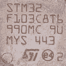
You likely have boards with the wrong CPU chip installed. At 1:30 in your YouTube video, I see 32K.
I received three new boards this morning that report as 32K and do not work. The other boards I have here report 64K and work correctly.
Working boards:./st-info --probe
Found 1 stlink programmers
serial: 513f6906493f51504816093f
openocd: "\x51\x3f\x69\x06\x49\x3f\x51\x50\x48\x16\x09\x3f"
flash: 65536 (pagesize: 1024)
sram: 20480
chipid: 0x0410
descr: F1 Medium-density device
Working:
- STM32-working.png (3.5 KiB) Viewed 353 times
I’m not sure how “st-info” makes its determination about the IC.
My best guess is that the chip that didn’t work is a cheaper ST device re-labelled as the F103 e.g. perhaps its a F101?
(But I don’t know what F1 series would match the results given my st-info, (assuming what st-info reports is correct …..))

Based on the STM32 data sheet, I’m guessing these are probably STM32F103C6.
st-info (Linux), ST Demonstrator GUI (Windows), and ST-Link Utility (Windows) all agree on the memory and the device ID.
Seems you are not the first: Fake STM32 “Blue Pill” Boards
You have two options:
Option 1)
Install Roger’s libmaple core. This is the one that works with the DFU user bootloader:
https://github.com/rogerclarkmelbourne/Arduino_STM32
After you install Roger’s core please select the proper board:

Option 2)
Continue to use the STM official core, and use the ROM bootloader with your FTDI USB serial dongle as the uploader.
Also, could you please provide the vendor that sold you that bluepill so the rest of use can avoid this pain?
[RogerClark – Wed Jan 16, 2019 2:06 am] –
Alexpress are often very good with getting a refund. So you may be able to get your money back
On the positive, 32k flash is the same as UNO Atmega328P, but 10K SRAM is 5X the UNO and 72MHz is 6X the clock, so at $1.69 each delivered, the mutant faux clone Blue Board is still a useful board.
Based on my experiences… For small quantities, the Aliexpress.com vendor is likely to issue a full-refund and reject return of same.
But this chip-swapping was bound to eventually happen, IMO. eBay and Aliexpress.com vendors with good ratings are apparently caught up in this deception; and I doubt it it is on a small scale as the grinding and relabeling is not without cost. Until this shakes out, any reseller is suspect. Again, more than before, we are in a “buyer beware” marketplace. Someone just threw cold watter on the hot Blue Pill market.
Ray
The link from fpiSTM on the fake boards has instructions on modifying the linker and boards.txt files to allow compilation. I’ll have to experiment and see if I can make these work. Rarely does one of my programs need more than 32kb of flash.
I also tried to get Roger’s core working, but am not successful yet. This would be the most desirable outcome, as many things seem to be missing for the blue pill in the official fpistm core.
[fredbox – Sat Jan 19, 2019 3:46 pm] –
I also tried to get Roger’s core working, but am not successful yet. This would be the most desirable outcome, as many things seem to be missing for the blue pill in the official fpistm core.
Which things?
CDC is in the current github version, DFU should come with 1.5.0 (I hope).
[fredbox – Sun Jan 20, 2019 12:01 am] –
Once I enable CDC and use Serial.begin compilation fails with an out of ram error (need another 1K). If I compile for a standard blue pill with 64 or 128K, compilation is successful.
Compilation is important, but the running system may likely fail due to SRAM exhaustion: stack and/or heap. Bottom line: 10K SRAM and 32K flash means the programmer must be judicious about how to use these reduced resource uC’s. Still, for the right application and for under $2 per board, these are rather useful even if half of what was expected.
Ray
[fredbox – Sun Jan 20, 2019 12:01 am] –
Once I enable CDC and use Serial.begin compilation fails with an out of ram error (need another 1K). If I compile for a standard blue pill with 64 or 128K, compilation is successful.
AH OK gotcha, yes, the current github base version of CDC has ~ 6K of buffers allocated, there’s a PR in that shrinks this down to ~256 bytes, see PR#399 -> https://github.com/stm32duino/Arduino_C … 2/pull/399
It’s awaiting a rebase, which I guess Frederic will get around to this week.
[BennehBoy – Sat Jan 19, 2019 5:47 pm] –
Which things?
I’ve had a few days to experiment with the “official” core. on my fake and genuine blue pill boards. I guess the main thing I miss is an easy to use hardware timer. I compiled the blink example using a timer from another thread and it works, but is a bit more complicated to set up. Also timer related, I use systick_attach_interrupt() in Roger’s core for blinking leds and scanning inputs such as rotary encoders and switches. I’m sure it will get easier as I read the documentation and get more familiar with the core. It took a while to get comfortable using the Roger/Leaflab core.
The part number from the STM datasheet for a part with these specifications is STM32F103C6T6. I copied the linker script and added four lines to boards.txt for the fpiSTM core with for a part with these specifications and it appears on the menu as a blue pill with 32K. I can compile and upload simple programs and they execute successfully. Serial works on the UART pins, but USB serial takes too much memory for now.
[fredbox – Thu Jan 24, 2019 3:00 am] –
…
Serial works on the UART pins, but USB serial takes too much memory for now.
USB serial is vastly overrated ![]()
While using a Maple Mini clone with USB serial is “nice” for debugging statements on the ArduinoIDE serial console, it rarely is needed after development where a Blue Pill or this new resource crippled-Bluepill will suffice.
With the increased Internet stories about the under $2 Blue Pill, the demand was sure to create a market for Asian suppliers of fake merchandise. I strongly suggest all who are in receipt of fake marketed Blue Pills to demand a full refund… only then will distributors vet their suppliers to ensure quality parts. But, if the seller refunds your money and allows you to keep the faux board, it still has project value.
Ray
[RogerClark – Thu Jan 24, 2019 8:45 am] –
I’ve also used Serial USB in some of my projects, hence the current screw up when I removed the requirement for devices to set DTR, as a lot of software (in my case it was Stellarium) does not set DTR
[BennehBoy – Thu Jan 24, 2019 7:18 am] –
It may be overrated but it’s very handy for bootloading. (although with 32kb flash I concede the point on this chip… still 2kb hid BL)
A few years back, I purchased a large number of those Chinese CH340’ish adapters. I find this to be a preferable solution and removing USB-serial from the Pill board leaves the uC without the need to deal with CDC serial concerns – just makes a software design a wee bit simpler with interfacing requirements can be moved to dedicated hardware. I just checked AliExpress, the CH340 is only $0.59 quantity one, free shipped.
Ray
[BennehBoy – Thu Jan 24, 2019 4:11 pm] –
Each to their own
True. But, the LOL should be more of a geek’ish icon. I prefer ![]()
3 lines changed in variants/BLUEPILL_F103C8/ldscript.ld:
-**                64/128KByte FLASH, 20KByte RAM

+**                32/64/128KByte FLASH, 10/20KByte RAM
-_estack = 0x20005000; /* end of RAM */
+_estack = 0x20000000 + LD_MAX_DATA_SIZE; /* end of RAM */
-RAM (xrw) : ORIGIN = 0x20000000, LENGTH = 20K
+RAM (xrw) : ORIGIN = 0x20000000, LENGTH = LD_MAX_DATA_SIZE
[fredbox – Sat Jan 26, 2019 5:59 pm] –
I’ve updated to the latest fpiSTM Github code from yesterday and modified boards.txt and ldscript.ld for the 32k parts. I don’t have a Github account, so here are my changes if anyone else needs them:3 lines changed in variants/BLUEPILL_F103C8/ldscript.ld:
-**                64/128KByte FLASH, 20KByte RAM

+**                32/64/128KByte FLASH, 10/20KByte RAM
-_estack = 0x20005000; /* end of RAM */
+_estack = 0x20000000 + LD_MAX_DATA_SIZE; /* end of RAM */-RAM (xrw) : ORIGIN = 0x20000000, LENGTH = 20K
+RAM (xrw) : ORIGIN = 0x20000000, LENGTH = LD_MAX_DATA_SIZE
I’ve made a fix to build properly for a C6.
Number of peripheral is not the same between STM32F103C6 and CB
C6 does not have USART3 and TIM4.
https://github.com/BennehBoy/Arduino_Core_STM32/pull/1


