headers for oled, nrf24, esp8266 and bluetooth, uart and swd to 2×4 header
http://www.ebay.co.uk/itm/191974161480? … EBIDX%3AIT
a rather neat small board
stephen
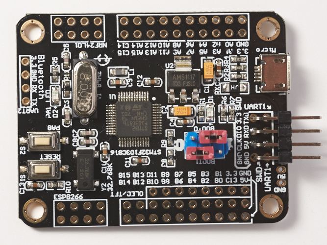
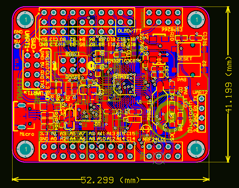
Looking at BP board it seems there just be enough space for one WB SPI Flash chip on bottom side ![]()
USB seems to be connected and there is a 1.5k USB pullup (which is correct)
i also included an AAA battery for sizing, short side is 1 AAA in length, long side ~1.5??
sot pads for 24c02 and flash are marked as such, also more pads ( identified by D/R/C) for the support components, so i expect
some work in finding appropriate values, but straightforward work.
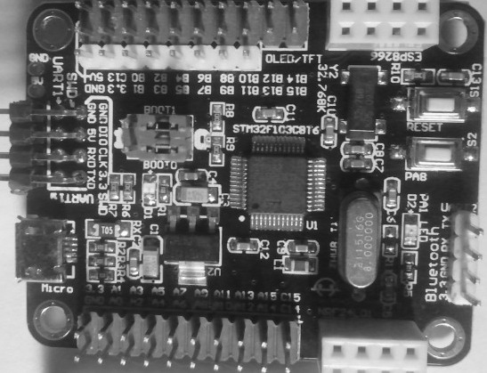
seems to have button on PA8, LED on PA1 ?? ??
headers,
2 off 2×20, [A0-A15, C14, C15, 3v3, GND] [ B0-B15, C13, 3v3, 5v, GND]
1 off 4×2 [GND, SWD, SWCK, 3V3] & [TXD, RXD, 5V, GND]
1 OFF 4X1 [3V3, GND, RX, TX]
pth for 5v & GND, regulator is an AMS117 type
if there are any conflicts is unknown, but someone put in time and effort. i wonder if i can find a schematic … … …
nrf24 and esp8266 at the same time ??
stephen
if you order 2, you save £1 on the price of 2 times 1 off. i did again
Even if 24C02 was already soldered, I would rather unsolder it and resolder a bigger one.
did it again & zoomed icon view
ok it saved them in 2005 – why oh why
dimensions – more like 1 x 1.25 AAA
took top and bottom, opened in gimp, did a really zealous crop, saved as xcf and exported as jpg (250k/500k)
redid as png – nope way too big
changed to greyscale
judges marks for readability please, n.b. tft-oled not labeled with pins
- neat-tidy-top.jpg (87.26 KiB) Viewed 2649 times
– soic8 and sop8 are synonym. Flash there soic8W (wide 208mil version)
– don’t use 24C02, place a 24C32 or higher such 24C512, they are pin compatible. (64KB vs 256 bytes)
However best to get out the calipers and check. => http://www.topline.tv/SizeChart.html
i’m in the uk and shipping is list as from somewhere to the east.
STM32F103C8T6 ARM Minisystem Development Board STM32 Development Core Board CK…
STM32F103C8T6 ARM Minisystem Development Board STM32 Development Core Board CK
Estimated delivery: Thu. 15 Dec. – Wed. 18 Jan.
Item ID: 191974161480
Transaction Id 1333131683009
Quantity: 2
can anyone tell me a sensible price for a AT24C256 £1.81 for 10 off seems slightly suss
oh well they 35 orders and 10 for £1.87
https://www.aliexpress.com/snapshot/853 … 2632083200
stephen
srp
and there was me thinking it’s just the 3 (1206 0805 0604) i need to worry about
link, bit overwhelming but useful.
@evildave_666
regular suppliers? price?
@roger
please snaffle those pics for the wiki if you want to. maybe slot it in above 103 with nrf24 and its variant 107 ?
stephen
the feline has found herself a cubby hole in one of my heaps, as she grooms, the whole of it rattles
she does a lot of grooming. ![]()
evidently she tidied house, disturbed a tin box full under there. almighty clang from it.
i don’t mind her stepping across me, but not in 2 bounds and all i get is a view of her tail. she could least say hello ![]()
zmemw16 wrote:i must be a fan, just ordered 2 more.
i’m in the uk and shipping is list as from somewhere to the east.
STM32F103C8T6 ARM Minisystem Development Board STM32 Development Core Board CK…
STM32F103C8T6 ARM Minisystem Development Board STM32 Development Core Board CK
Estimated delivery: Thu. 15 Dec. – Wed. 18 Jan.Item ID: 191974161480
Transaction Id 1333131683009
Quantity: 2
can anyone tell me a sensible price for a AT24C256 £1.81 for 10 off seems slightly suss
oh well they 35 orders and 10 for £1.87
https://www.aliexpress.com/snapshot/853 … 2632083200stephen
zmemw16 wrote:
@evildave_666
regular suppliers? price?
£4.86 == $6.12 – close enough ![]()
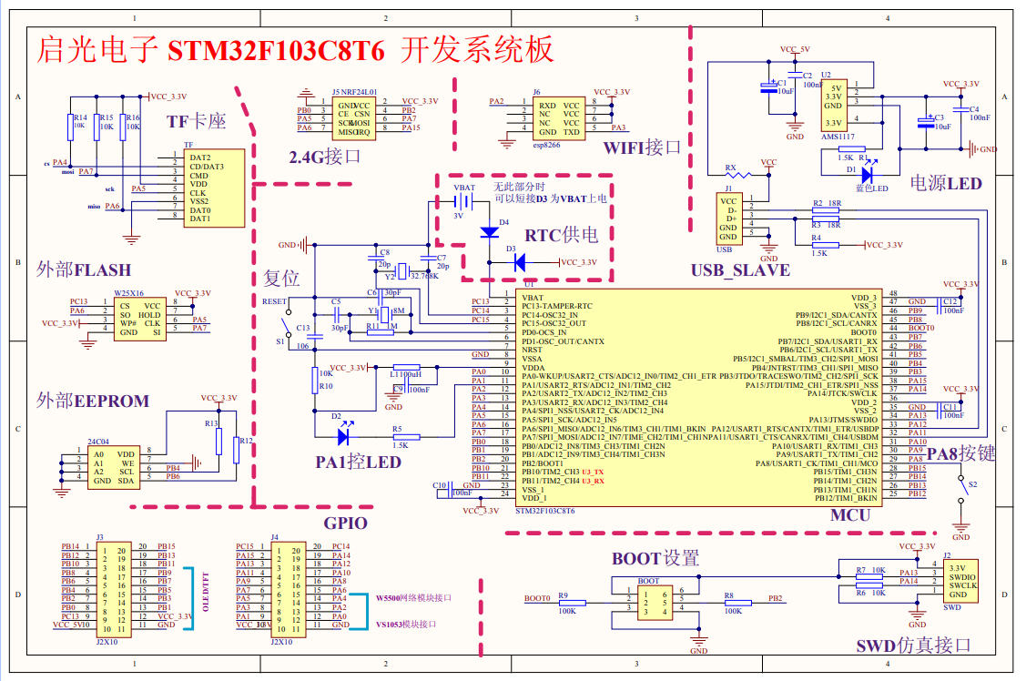
isn’t that sch missing an oled connector ? saved anyway.
stephen
srp
Generic 2.0 bootloader on pa1 binary from the github works fine. USB upload worked from the first go after getting the bootloader on.
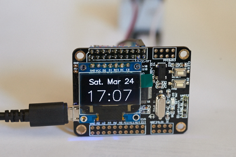
Note that the swdio and swclk labels on the board’s silkscreen are swapped from what they should be. Also if it wasn’t clear, the TFT/OLED pins are just tied to the pins adjacent to them on the 20-pin header.
// Declare the instance that the users of the library can use

//TwoWire Wire(SCL, SDA, SOFT_STANDARD);

//TwoWire Wire(PB6, PB7, SOFT_STANDARD); // this is how the wire.cpp file originally is

TwoWire Wire(PB4,PB6,SOFT_STANDARD); // EEPROM pins in the blackboard
there is probably more documentation than anything else on this machine, from A Touch of Frost – lottery win – he lost it;
” paperwork Jack, i keep telling you, paperwork” !
or something close.
i’ve only just again found my SMT soldering station.
but my 24c256’s have arrived which is what prompted the search, solder is next … … … paper index after that !
stephen
zmemw16 wrote:please, please, it would be really nice if you put up a picture of whatever connections are hiding behind the board and display.
there is probably more documentation than anything else on this machine, from A Touch of Frost – lottery win – he lost it;
” paperwork Jack, i keep telling you, paperwork” !
or something close.i’ve only just again found my SMT soldering station.
but my 24c256’s have arrived which is what prompted the search, solder is next … … … paper index after that !stephen
i was after the circuit/sketch on the paper, there were some strange to me at least port numbers. i suspect that’s the esp socket?
for example my 103rc boards with just a nrf24 socket, it’s on spi 1 pins a4-a7 with cs & irq on port c4 & c5 istr
regarding alternate functions, 407xx pdf has 9 pages of it, i’m wondering if there’s the same or more for 103. what chance the same mapping ????
stephen
well, found them and most definitely not the same format / mechanism
RM0008 Reference Manual STM32F101xx, STM32F102xx, STM32F103xx, STM32F105xx and STM32F107xx advanced ARM®-based 32-bit MCUs
November 2015 / DocID13902 Rev 16 / 1137 pages
and its 21 or so pages for the 103. start page may well be early at 174(182??) ends about 195.
stephen
Guess what?
Works perfectly with the default SD library. Chipselect pin is PA4. It could use an activity led to indicate when the pin is pulled low, like on some micro-sd card readers.
oh, so i didn’t actually need to solder those resistors in
srp
that’s about as good as it gets, however most of it is boiler plate.
if you can find any one of PA4-PA7, that’s SPI1 etc.
same sort of thing for the I2C & UART’s etc
OLED might be a problem.
all a bit of match the blobs jigsaw ![]()
i just tried looking at it with GIMP, it is just about readable.
stephen
The NRF2401 Socket should be:
1 GND

2 VCC

3 PB0 CE

4 PB2 CSN

5 PA5 SCK

6 PA7 MOSI1

7 PA6 MISO1

8 PA15 IRQ
1 GND
2 VCC
3 PB0 CE
4 PB2 CSN
5 PA5 SCK
6 PA7 MOSI1
7 PA6 MISO1
8 PA15 IRQ
Thx
Sorry for late reply… got the NRF working on this board using the RF24-STM https://github.com/jaretburkett/RF24-STM. I Used the RF24(PB0,PB2) and used autoACK, dynamic Payload and enableackpayload features.
As already mentioned I use this for my DIY RC transmitter / drone. The ackPayload gives some info back from the drone ( Battery voltage, pressure, heading,…). Its already working on arduino, I’m trying to port the code to STM32 with the magnificent help of the video of Joop Brokking (
Happy 2018!
srp
there’s a space in the link – missed it completely.
srp
https://www.youtube.com/playlist?list=P … LQVkDFHbxC For his videos on his STM32 drone project.
D
[electrobling – Sun Jan 28, 2018 12:00 am] –
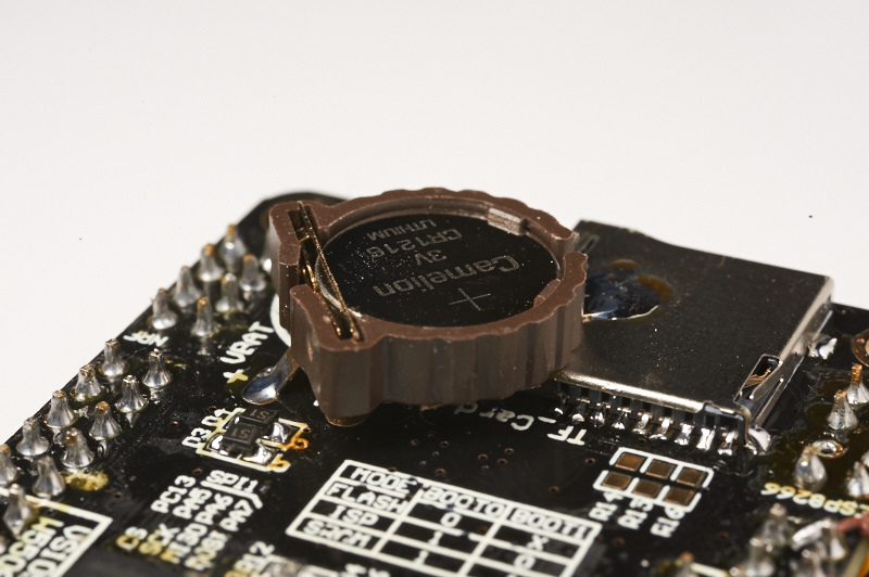
One possibly strange thing I noticed – the VBAT pin has diodes on it. One to the battery, one to VCC_3.3V. It looks like they want to relieve the battery when the power is on. But looking at the processor data sheet, it looks like it has provision for that internally. I haven’t seen other boards that have a provisioned battery backup, so I don’t know if it is really needed or if it is a standard practice. With simpler boards, I hope I can just connect the battery to VBAT and not worry about it.
I think the diode to VCC is to prevent the backup battery from powering the entire circuit when the main power source is removed. The internal diode was meant to protect against reverse voltage whilst the external added diode to VBAT may be a zener diode clamping the voltage to 3.3V.
It will be a few weeks before my boards arrive, so I can’t try it, but it seems to me that the processor must adequately isolate the battery when power is off, and the designers of this board just got paranoid and threw the isolation diodes on without testing.
See 5.1.6 Power supply scheme on page 36/117 of the data sheet.
I’ll buy the explanation of battery reverse voltage, as it is possible to stupidly insert a coin battery backwards. However, I think the chances of a higher voltage than 3.3V appearing there are almost nil, so although it is a bit of mind reading without proof, I think the intention was to supply voltage from VCC in the absence of a battery. In other words, confusion. ![]() Or it was cloned from some other device.
Or it was cloned from some other device.
Edit – this board does not have a removable battery, it’s soldered in. I think the ability to check polarity is assumed with the ability to solder. ![]()
Anyway, it is important to me because a working RTC is a big part of my plans.
srp
Edit – I should really download the other processor data sheets and compare. None of those are 103C version.
not a good result
a very long time ago, i used a transformer 6v ac winding, full diode bridge and a 6v dc capacitor for smoothing.
i also discovered i could navigate 3 floors of stairs to the water tap with my eyes shut.
then again i’ve never repeated it either.
when looking at the schematics, we need to work out how the designer sees the peripheral devices.
it maybe that they don’t see them as straight out interfaces, but in order to get the required devices to meet their specifications they’ve used that ability to remap ( move ) them to different pins.
so we read the schematic and because of remapping means they’ve moved spi1 to the spi3 pins and i2c1, spi2, i2c2 … … etc as an example they might need both 3v3 & 5v tolerant spi interfaces, moving spi1 (portA 3.3v) to spi3 (portB 5v)
also they might as all the outside world (us) uses them rename(renumber) the interfaces spi1->sp3 spi2->spi1 etc
stephen
[stevestrong – Fri Feb 02, 2018 5:13 pm] –
If you got blue pills, then do not wonder, 2 out of 10 cheap boards are statistically “bad”, showing not working USB, or not starting crystal.
After some inspection, it seems that pin 1 and pin 2 on the micro-usb connector seems to be shorted. Looks like I have to reflow that connector and see if it works properly after that.
- CIN_1296.jpg (209.07 KiB) Viewed 606 times
- CIN_1279 (1) .jpg (230.94 KiB) Viewed 603 times
[zoomx – Sun Mar 25, 2018 6:28 pm] –
I have populated the microSD slot.
Great. I have 10 holders on order. I placed D3 so that VBAT is powered from VCC, even if there is no battery. That should improve LSE stability. If you use the LSE, and plan to never place a battery, the pads could be shorted to do that. I will pull a pin from the ESP socket and jumper CH_PD to PB14 so I can shut down the ESP-01 when it is not in use.
- CIN_1333.jpg (184.39 KiB) Viewed 364 times
It’s a PDF, and it seems like there’s also a pcb design file. What program uses .PCB?
There are also some larger files, but I can’t seem to download them without installing a chinese botnet app.
Check this out:
[aroldorosenberg – Mon Feb 04, 2019 12:18 am] –
I found the schematic for this board in a taobao listing.
Great! Thanks for sharing your findings. The schematic posted earlier on the thread had some an annoying overlay. Unfortunately I don’t know the answer to your question.
Board design:
Schematic:

