Hi there!
Maybe this could be moved to the relevant section in the forum!
I’ve just got to know the BluePill and I’m now migrating all my personal projects (AVR 8-bit based) to ARM!
One of my first needs was a very small bootloader that I can use in my projects. Tried stm32duino bootloader (Thanks, Roger, for the great work on it!), but I needed something simpler, smaller, driverless and compatible with latest GCC toolchains.
So I came up with this small bootloader:
https://github.com/bootsector/stm32-hid-bootloader
Maybe that could be useful for some of you guys!
Cheers,
bootsector
Interesting
Can you link to the program used to upload to this bootloader e.g. what is hid-Flash
PS. I have seen similar bootloaders that enumerate as USB mass storage, but also need a special uploader.
However they were much bigger than 1k in size.
Also on an unrelated note, I have noticed a trend for companies now to use raw HID for their products, because Windows doesnt need a special driver.
Well, the dfu bootloader does not really need a driver dll to be installed, all the installer does is associate the dfu driver that comes with Windows to be associated with the USB VID PID of the bootloader
But Microsoft’s approach has just moved the perceived problem of not allowing unknown devices to connect, and now all devices masquerade as HID or mass storage even if they are a completely different type of device
hid-flash sources is also included in the repo: https://github.com/bootsector/stm32-hid … master/cli
Trigger condition for the USB HID bootloader is pulling A8 LOW during startup.
Cheers,
bootsector
[Slammer – Sun Apr 15, 2018 2:46 pm] –
And the vector table is redirected to 0x8001000, as I can see…
Correct! That’s where user program should go, so make sure to adjust your vector table when using this bootloader.
The bootloader takes the first three 1K flash pages. Another 1K flash page is reserved for user configuration data, if desired.
So total size is 4K ?
But it should be possible to change that to jump to the existnug Address used by LibMaple as it’s start address
Does it check if a sketch already exists and flash the led etc and then jump to the sketch after a few seconds ?
Does it support locking in hid bootloader mode using the battery backed ram registers ?
It’s just a shame on Windows that the serial driver still needs to be installed ![]()
[RogerClark – Sun Apr 15, 2018 9:24 pm] –
So total size is 4K ?
That’s correct, I’m reserving the first 4K for the bootloader itself plus some space for optional user program configuration data
But it should be possible to change that to jump to the existnug Address used by LibMaple as it’s start address
Right, bootloader can be configured to jump to any flash address you want!
Does it check if a sketch already exists and flash the led etc and then jump to the sketch after a few seconds ?
It just jumps to the defined user program address without checking anything if A8 is not LOW when bootloader runs.
Does it support locking in hid bootloader mode using the battery backed ram registers ?
If bootloader is activated by driving A8 LOW while it starts, firmware will be in HID USB mode until manually restarted or disconnected.
It’s just a shame on Windows that the serial driver still needs to be installed ![]()
I’m not sure what you mean here. No drivers should be needed to be installed even on windows.
Just for clarity, this is a very simple and straightforward bootloader. It fits my use cases just fine, but it might be useless for other use cases though.
[RogerClark – Sun Apr 15, 2018 9:24 pm] –
It’s just a shame on Windows that the serial driver still needs to be installed
I think Roger means the general USB serial functionality. For code upload only, this bootloader should work without drivers. I think nobody in this forum will use/program/debug without serial, but building things for third persons this bootloader would be from interest.
[madias – Sun Apr 15, 2018 10:09 pm] –[RogerClark – Sun Apr 15, 2018 9:24 pm] –
It’s just a shame on Windows that the serial driver still needs to be installedI think Roger means the general USB serial functionality. For code upload only, this bootloader should work without drivers. I think nobody in this forum will use/program/debug without serial, but building things for third persons this bootloader would be from interest.
Gotcha! Yeah, serial functionality should be inside the user program and that would require a windows driver, for sure!
I really like the idea of the driverless installation of the bootloader, and that it’s only 4K.
Using a special program to upload is also Ok, as we currently have to use DFU-Util and that needs versions for every platform.
I think it should be easy to take the code from the Stm32dunno bootloader which checks if the program start address ram vector contains real data, and then jump after a predefined delay
And flash the LED while waiting , and also do the USB bus reset..
And still be under 4K
Also..
Do you think it would be possible to compile this for the F4 series
As we desperately need a bootloader or the F4
Yeah, checking for valid code before jumping should be very straightforward to implement. Additional custom commands could also be implemented, including USB reset.
What cheap F4 board do you recommend? I can purchase one and try to port the bootloader to it.
A scenario could be a outdoor or hard to access indoor device so you can program it with a OTG capable Android smartphone (I think all of them are USB OTG meanwhile) the easy way without balancing a laptop on the last stage of the ladder.
[madias – Sun Apr 15, 2018 10:23 pm] –
F4 board: There is a F4-bluepill under construction in this forum. I ordered this one (well supported here): https://www.aliexpress.com/item/Free-sh … 84907.html
Awesome! Thanks! I will order one of those. It could take a couple of months for it to arrive here in Brazil, though… ![]()
Can you link to F4 CMSIS files ??
I will clone the repo and add them etc
[RogerClark – Sun Apr 15, 2018 10:47 pm] –
Can you link to F4 CMSIS files ??I will clone the repo and add them etc
Everything should be inside this big zip package: http://www.st.com/en/embedded-software/stm32cubef4.html (scroll down to the end until you see the blue “Get software” button).
Edit: Looking at the reference manual, the F4 board uses a completely different USB peripheral compared to the F1. So this should be more of a completely rewrite than a direct port…
Ah.
OK.
Thats a shame about the F4 needing a complete re-write.
We have the same problem on the stm32duino bootloader, as it doesnt even use the CMSIS, it just controls the ports directly.
So changing it to work on the F4 would require lots of changes.
Did you consider using LibOpenCM3 ?
I guess perhaps the resultant binary was much bigger
[bootsector – Sun Apr 15, 2018 9:51 pm] –
That’s correct, I’m reserving the first 4K for the bootloader itself plus some space for optional user program configuration data
Wow, that is one compact bootloader. I’ve seen another bootloader that weighed in around 4KiB, but it made extensive use of hand-written assembly everywhere, particularly for the USB stack. I’m impressed.
As a friendly word of advice, I noticed that you’re using USB vendor ID F055, which doesn’t seem to be publicly assigned by the USB-IF. There shouldn’t be any issue doing that for personal use, but in case your project becomes a major success and starts conflicting with some future company that uses that VID, you might want to get a dedicated USB VID/PID pair.
The pid.codes project and OpenMoko both maintain free USB PID allocation programs for open source hardware/software/firmware projects. I’ve used pid.codes before – it’s a very simple process to get your PID assigned.
[madias – Sun Apr 15, 2018 10:21 pm] –
Driverless bootloader would make another thing possible:
A scenario could be a outdoor or hard to access indoor device so you can program it with a OTG capable Android smartphone (I think all of them are USB OTG meanwhile) the easy way without balancing a laptop on the last stage of the ladder.
Not to derail this discussion too much, but that is actually possible already, today, using WebUSB. If you put the normal stm32duino bootloader into persistent bootloader mode, you can use my demo to load a .bin file over the DFU interface.
[RogerClark – Sun Apr 15, 2018 11:15 pm] –
Ah.OK.
Thats a shame about the F4 needing a complete re-write.
We have the same problem on the stm32duino bootloader, as it doesnt even use the CMSIS, it just controls the ports directly.
So changing it to work on the F4 would require lots of changes.
Did you consider using LibOpenCM3 ?
I guess perhaps the resultant binary was much bigger
I didn’t consider to use any third party library, as I wanted to learn and use the blue pill available peripherals to the register level by only using CMSIS. F4 register references and interrupt related constants should be available on its CMSIS header, so if one day I come up with a bootloader for it, I will be using only CMSIS as well.
[devan – Sun Apr 15, 2018 11:43 pm] –
As a friendly word of advice, I noticed that you’re using USB vendor ID F055, which doesn’t seem to be publicly assigned by the USB-IF. There shouldn’t be any issue doing that for personal use, but in case your project becomes a major success and starts conflicting with some future company that uses that VID, you might want to get a dedicated USB VID/PID pair.
Thanks for the tip! I will definitely register for a PID! 0xF055 was a failed attempt to make available VID for open source projects in the past. It looks like there are some people trying to revive it here https://f055.io/
Edit: just created the PR: https://github.com/pidcodes/pidcodes.gi … m/pull/320 ![]()
I just forked your repo and tried to compile but it looks like it may only work with newer versions of Gcc
Can you tell me which version you are using, as I’m getting compile issues with c99 errors, which I resolved but it now does not recognize asm as a command.
[RogerClark – Mon Apr 16, 2018 10:17 am] –
I just forked your repo and tried to compile but it looks like it may only work with newer versions of GccCan you tell me which version you are using, as I’m getting compile issues with c99 errors, which I resolved but it now does not recognize asm as a command.
I’m using
gcc-arm-none-eabi-7-2017-q4-major-mac.tar.bz2
I didn’t actually tested with older toolchains. I will do that and make the necessary adjustments so it works with older toolchains when I have a chance.
OK
No worries
I tried with 4.8
I think I have some other newer versions installed but not in my path
Not sure why it doesnt accept the asm commands, possibly something missing from the CFLAGS
I’ll check
I made a few changes and got it to compile with gcc 4.8
I needed to replace asm with __asm__
and also the linker command -Wl,–print-memory-usage was not supported, so I commented it out
file size of the bin is 2,988 bytes
How big is your bin file
(PS not actually tried it yet, probably won’t have time this evening to test it)
BTW. I had to add
CFLAGS += -std=c99
as well to get it to compile with gcc 4.8
BTW. One thing I noticed in your code is the jump to the user program
I recall this had issues in the stm32duino bootloader in some versions of gcc
Obviously it worked for you, but I recall something far more complex being needed for other compiler versions (though I can’t remember the precise details)
Awesome! I will check the generated code size, but I remember it getting below the 3000 bytes as well.
If possible, try to add -std=gnu99 instead of plain c99 since gnu extension has some additional features.
From what I’ve read about the user program jump, you need to make sure that a pop is not generated by the assembler after the jump call. In order to verify that, you can issue make main.s and see the generated assembler code.
Thanks
I will check tomorrow
PS. You may like to add the Windows etc binaries onto GitHub, often people just want to install and use the bootloader but not compile it.
So put the bootloader bin in GitHub as well
This is the bootloader compilation stats by using the gcc-arm-none-eabi-7-2017-q4-major toolchain:
Memory region         Used Size  Region Size  %age Used

RAM:        2760 B        20 KB     13.48%

FLASH:        2920 B        64 KB      4.46%
This is very nice!! I think it shows good potential to be used as a general purpose compact bootloader.
I just spent my lunch hour testing it on Linux and my locked down Win7 work PC. I was able to load a simple timer controlled blinky on both without needing special permissions or drivers.
A couple of comments though
- when PA8 is high the device is still appearing as a usb device (unknown on Windows) and generating errors on Linux (unable to enumerate USB device). I think, it would be better not to appear as a device.
- I think the descriptor is missing a string field. On Linux I get (string descriptor 0 read error: -22) when PA8 is low
I can’t comment on the speed since I was only loading an 1100 byte binary.
When I get the chance I certainly want to have a look at the code to see how you have implemented it.
Eric
[eggsylah – Mon Apr 16, 2018 7:16 pm] –
[*] when PA8 is high the device is still appearing as a usb device (unknown on Windows) and generating errors on Linux (unable to enumerate USB device). I think, it would be better not to appear as a device.
If you are using a Blue Pill, make sure your user program calls USB_Shutdown() (from usb.c) as the first thing, otherwise Windows will try to enumerate the board since it has a pull up resistor on A12. This is necessary if your user program doesn’t implement an USB device.
[*] I think the descriptor is missing a string field. On Linux I get (string descriptor 0 read error: -22) when PA8 is low
I will look at that. Did you flash the firmware under Linux?
Edit: You don’t necessarily have to call USB_Shutdown() in order to deactivate USB on your program if you are not using it. You can simply configure A12 as output and drive it LOW. This is not related to the bootloader but to the BluePill that has USB always enabled via physical pullup resistor.
I think it would be better if you did not need to use an external pin to force into bootloader mode.
Timeout is better.
Also use a battery backed ram register to lock the bootloader in upload mode following soft reset from the application program would be good.
[RogerClark – Mon Apr 16, 2018 9:04 pm] –
I think it would be better if you did not need to use an external pin to force into bootloader mode.Timeout is better.
Also use a battery backed ram register to lock the bootloader in upload mode following soft reset from the application program would be good.
A timeout will interfere with my use cases and an external pin works best for me. I might work in a configurable option inside Makefile in order to allow the user to select how to go into USB HID mode in the future.
I’ve released a binary version: https://github.com/bootsector/stm32-hid … r/releases
@eggsylah
I’ve updated the firmware so it should now return String descriptor 0 (Lang ID) correctly in your Linux box. Let me know if otherwise.
Cheers,
bootsector
I updated to your latest version and the string error has gone.
I also followed your advice about PA12 and that has stopped the USB errors I saw on Linux and the unknown device on Windows.
So it is looking good on my side.
Yes I was using Linux and a regular bluepill board.Roger,
I think the idea would be to see if this approach was worthwhile and then try emulating the way the current bootloader works (eg timeout and all other features).
I’d like to see if I can make it work on my L462 blue pill board
Eric
OK
I’ll pull the latest changes and then investigate adding a timeout rather than using an external pin.
I’ve also changed the source so it compiles and links with older versions of GCC e.g the version used by the Arduino IDe
Although wastes 4k of Flash, I’ll initially set the application start address to the 8k location to match the best LibMaple based (stm32duino) bootloader
I’ve pushed a new version that aside of checking for A8 as LOW, alternatively it will also check for BOOT1 jumper as 1. So keeping BOOT0 as 0 (default) and BOOT1 jumper as 1, USB HID bootloader will kick in. I think this is a nice addition for the Blue Pill since the jumper is already there to be used! ![]()
@bootsector
Great job ! Well done. I slightly modified your source code to work with the Arduino IDE upload method: STM32duino bootloader on STM32F103C8 bluepill
For those who want to try that HID bootloader:
- Burn the bluepill with the attached HID bootloader (HIDBOOTLOADER.bin file).
- Select the upload method: STM32duino bootloader from the Arduino IDE
- Compile your sketch
- Find where your compiled .bin file exists (for example: Blink.ino.bin) and copy it to the same folder where hid-flash.exe exists
- Connect the PA8 to the GND and reboot the bluepill.
- Execute the following CLI command
hid-flash.exe blank-config.bin Blink.ino.bin
I only find this really feasible if I don’t need to mess with extra pin setting (PA8 to GND and then release).
So for me it should be able to automatically:
– get a “magic sequence” to reboot in bootloader (or wait for it a while after a reset)
– flash the new software and
– run the newly flashed sw
as the current stm32duino bootloader does.
Looking forward to test such a version.
EDIT
I think we need an extra entry under “Bootloaders and Cores” to move this topic.
[stevestrong – Tue Apr 17, 2018 8:31 am] –
I only find this really feasible if I don’t need to mess with extra pin setting (PA8 to GND and then release).So for me it should be able to automatically:
– get a “magic sequence” to reboot in bootloader (or wait for it a while after a reset)
– flash the new software and
– run the newly flashed sw
as the current stm32duino bootloader does.Looking forward to test such a version.
Steve
I’ve already posted the same requirement
Also it needs to flash the LED slowly while waiting and quickly when flashing the sketch
[stevestrong – Tue Apr 17, 2018 8:31 am] –
I only find this really feasible if I don’t need to mess with extra pin setting (PA8 to GND and then release).So for me it should be able to automatically:
– get a “magic sequence” to reboot in bootloader (or wait for it a while after a reset)
– flash the new software and
– run the newly flashed sw
as the current stm32duino bootloader does.Looking forward to test such a version.
EDIT
I think we need an extra entry under “Bootloaders and Cores” to move this topic.
I agree with you. There is (almost) nothing that can not be done in programming. The basic (great) idea of a HID bootloader was achieved. The next step is to add the features you mentioned earlier.
Below should be the necessary steps in order to get automatic user code jump functionality:
– Add a flag that tells bootloader to jump to user code (initially set as false)
– Setup a timer ISR that will set user code jump flag as true after X seconds and no USB custom command received (this requires another flag)
– Activate USB HID
– Add a new custom command (i.e., {‘B’,’T’,’L’,’D’,’C’,’M’,’D’, 0x01}) that will set user code jump flag as true
– Change HIDUSB_HandleData() so it updates the custom command received flag used by the timer interrupt ISR
– Main loop should poll for the user code jump flag
– Before jumping to user code, call USB_Shutdown() from usb.c and turn timer off
On the CLI side:
– Send the new custom command after flashing is done
I will leave to the community to try that. If it takes too long and nobody comes up with something, I will implement it. ![]()
[stevestrong – Tue Apr 17, 2018 8:31 am] –
I only find this really feasible if I don’t need to mess with extra pin setting (PA8 to GND and then release).So for me it should be able to automatically:
– get a “magic sequence” to reboot in bootloader (or wait for it a while after a reset)
– flash the new software and
– run the newly flashed sw
as the current stm32duino bootloader does.Looking forward to test such a version.
EDIT
I think we need an extra entry under “Bootloaders and Cores” to move this topic.
Bootsector already added support for checking boot1 pin instead of A8, I think that covers the first point in the list, at least for boards with the jumpers, and the core function that reboots with DTR and 1eaf sequence should still work with this bootloder.
I think adding the option to stay in bootloader indefinitely if a) there is no sketch, or b) there is a magic word in backup register would make it match the current bootloader pretty close.
Changing the button pin to any other pin, should be a straight change. Originally the maple bootloader only included code for the original button and Roger added support for others with macros at compile time. Most likely the same can be done here without increasing sketch size a lot.
Blinking the led as Roger suggested would be a nice visual cue on what’s the bootloader doing.
I wonder if after all that it will stay under 3KB.
One more thing that would be nice is adding support for other page sizes, so it can be used with all F1 mcus, and perhaps later with F4, which include multiple page sizes in the same device.
Btw very interesting project and thanks to bootsector for sharing it.
It is possible the “magic sequence” to write something in a memory flag indicating that bootloader will be activated after reset.
So the bootloader activation can be done by one of these conditions:
1. applying a signal in Boot 1 or any other pin,
2. by a memory flag
3. In case of empty flash or bad crc of program.
With this operation it is possible to program and autoreset the board, with or without an additional wire or button.After all, if the size of bootloader stays below 4K limit, it is possible to give 4K more space in the program relocating the reset vectors at 0x8001000
I would think most of the changes requested can be ported straight from our bootloader (checking for the magic word, checking if something resembling a sketch is loaded, and blinking the pin)
I am sure that @RogerClark can answer for this.
I am working on this HID bootloader for adding the “magic sequence” and the DTR signal.
I have almost done it.
However at the moment the core does not set a magic number into DR10.The Maple bootloader ( stm32bootloader) already checks for DR10 and will hold in the bootloader if the magic number is found.
I wanted to add the magic number into DR10 into the core but I recall some people objected to this, but I can’t remember why.
IMHO it would make things a lot better as we could almost do away with the bootloader waiting time.
I also proposed using Boot1 was the Button pin for the BluePill, like has been implemented on this bootloader, but again there were a load of objections ( again I can’t remember why)
Perhaps is should pander less to small minorities and just implement both changes.
[Vassilis – Tue Apr 17, 2018 5:13 pm] –
I am working on this HID bootloader for adding the “magic sequence” and the DTR signal.I have almost done it.
This is untested:
/*

* STM32 HID Bootloader - USB HID bootloader for STM32F10X

* Copyright (c) 2018 Bruno Freitas - [email protected]

*

* This program is free software: you can redistribute it and/or modify

* it under the terms of the GNU General Public License as published by

* the Free Software Foundation, either version 3 of the License, or

* (at your option) any later version.

*

* This program is distributed in the hope that it will be useful,

* but WITHOUT ANY WARRANTY; without even the implied warranty of

* MERCHANTABILITY or FITNESS FOR A PARTICULAR PURPOSE.  See the

* GNU General Public License for more details.

*

* You should have received a copy of the GNU General Public License

* along with this program.  If not, see <http://www.gnu.org/licenses/>.

*/
#include <stm32f10x.h>
#include "usb.h"
#include "hid.h"
#include "bitwise.h"
// HID Bootloader takes 3K. 1K of config flash follows it.
#define USER_PROGRAM 0x08001000
typedef void (*funct_ptr)(void);
uint16_t get_and_clear_magic_word() {
bit_set(RCC->APB1ENR, RCC_APB1ENR_BKPEN | RCC_APB1ENR_PWREN);
uint16_t value = BKP->DR10;
	if(value) {

bit_set(PWR->CR, PWR_CR_DBP);
BKP->DR10 = 0x0000;
bit_clear(PWR->CR, PWR_CR_DBP);
}
bit_clear(RCC->APB1ENR, RCC_APB1ENR_BKPEN | RCC_APB1ENR_PWREN);
return value;
}
int main() {
uint32_t userProgramAddress = *(volatile uint32_t *)(USER_PROGRAM + 0x04);
funct_ptr userProgram = (funct_ptr) userProgramAddress;
// Turn GPIOA clock on
bit_set(RCC->APB2ENR, RCC_APB2ENR_IOPAEN);
// Set A8 as Input Mode with Pull-ups
bit_clear(GPIOA->CRH, GPIO_CRH_MODE8);
bit_clear(GPIOA->CRH, GPIO_CRH_CNF8_0);
bit_set(GPIOA->CRH, GPIO_CRH_CNF8_1);
bit_set(GPIOA->ODR, GPIO_ODR_ODR8);
// Turn GPIOB clock on
bit_set(RCC->APB2ENR, RCC_APB2ENR_IOPBEN);
// Set B2 as Input Mode Floating
bit_clear(GPIOB->CRL, GPIO_CRL_MODE2);
bit_set(GPIOB->CRL, GPIO_CRL_CNF2_0);
bit_clear(GPIOB->CRL, GPIO_CRL_CNF2_1);
// Wait 1uS so the pull-up settles...
for(int i = 0; i < 72; i++) {
asm volatile ("nop\n");
}
// If A8 is LOW or B2 is HIGH enter HID bootloader...
if((!(GPIOA->IDR & GPIO_IDR_IDR8)) || (GPIOB->IDR & GPIO_IDR_IDR2) || (get_and_clear_magic_word() == 0x424C)) {
USB_Init(HIDUSB_EPHandler, HIDUSB_Reset);
for(;;);
}
// Set A8 to input floating
bit_clear(GPIOA->CRH, GPIO_CRH_MODE8);
bit_set(GPIOA->CRH, GPIO_CRH_CNF8_0);
bit_clear(GPIOA->CRH, GPIO_CRH_CNF8_1);
bit_clear(GPIOA->ODR, GPIO_ODR_ODR8);
// Turn GPIOA clock off
bit_clear(RCC->APB2ENR, RCC_APB2ENR_IOPAEN);
// Turn GPIOB clock off
bit_clear(RCC->APB2ENR, RCC_APB2ENR_IOPBEN);
SCB->VTOR = USER_PROGRAM;
asm volatile("msr msp, %0"::"g"(*(volatile u32 *) USER_PROGRAM));
userProgram();
for(;;);
}
Thanks…
I think my the time PC13 LED flashing and timeout is added, 4K will be a realistic size. Which is still half the size of a DFU bootloader.
Can we leave clearing the magic word to the core rather than the bootloader?
This section
if(value) {
bit_set(PWR->CR, PWR_CR_DBP);
BKP->DR10 = 0x0000;
bit_clear(PWR->CR, PWR_CR_DBP);
}
I agree that we shouldn’t clear the magic (half-)word from inside the bootloader. So function would get as:
uint16_t get_magic_word() {

bit_set(RCC->APB1ENR, RCC_APB1ENR_BKPEN | RCC_APB1ENR_PWREN);
uint16_t value = BKP->DR10;
bit_clear(RCC->APB1ENR, RCC_APB1ENR_BKPEN | RCC_APB1ENR_PWREN);
return value;
}
Yes.
The register is only used because it survives a soft reset
If the power is removed, the register is erased
The reason is simple: the BP has not too many pins, the application may use all available pins, so that PA8 (or PB2 aka BOOT1) could be hardwired.
A pull down resistor on these pins would mislead the bootloader.
I think there will be lots of users complaining later in their application because of the sketch not running, similar to the debug pins…
Steve
I understand your concerns, but I’m not sure how many people would be using the Boot1 pin on the Blue Pill.
All pins on the side of the BP and possibly the SWD pins, but I’d be surprised if that many people use Boot1
I think the Maple mini uses Boot1 for its button, so it would be compatible with that as well.
If one agree on BOOT1, then PA8 can be left away, saving couple of bytes in flash.
I guess there is no need to have a button at all, if a timeout is used.
But the problem on one systems e.g. Mac the timeout needs to be very long to guarantee upload, as the USB seems to take a long to re-enumerate
[stevestrong – Wed Apr 18, 2018 5:33 am] –
I use PB2 for LCD projects (16 bit parallel), so I could put there a pull-up down to avoid any issue.
If one agree on BOOT1, then PA8 can be left away, saving couple of bytes in flash.
I think it reasonable to keep only B2 (BOOT1) pin checking (HIGH) for now. I’m removing the A8 pin check.
HID bootloader progress up to now:
- Added an extra menu to the Arduino IDE (STM32F103C8 variant): upload method: HID bootloader [Done]
- Made all modifications to the boards.txt and platform.txt files to use the new HID bootloader [Done].
- The Arduino IDE sends the DTR, RTS signals and the Magic sequence 1EAF to the STM32 [Done]
- If the sequence is correct, the STM32 reboots in bootloader [Done]
- It stays there for some time. If the upload is finished or the timeout occurs, the STM32 jumps to the user code [Done]
- Made the necessary modifications to the CLI file too (hid_flash.c)
I also used, the battery backed ram register for faster power-on the bluepill.
I need to make some more tests and then I will send a pull-request
Very cool…
I had a brief look at the code to see how easy it would be modify but the CMSIS is barely above hardware level access, and needs a detailed understanding of the bits in each control register
I wonder how hard it would be to port to the F4. But I susoect it’s not that easy.
[RogerClark – Wed Apr 18, 2018 9:28 pm] –
Very cool…I had a brief look at the code to see how easy it would be modify but the CMSIS is barely above hardware level access, and needs a detailed understanding of the bits in each control register
I wonder how hard it would be to port to the F4. But I susoect it’s not that easy.
CMSIS is pretty straightforward if you’re following the Programming/Reference Manuals and, personally, I think it works better than using a higher level library.
I came from the Arduino/Libraries world, then programmed a little bit of bare metal AVR as well and now I’m having a really good time and having lots of fun by writing my own device libraries on the STM32 by using CMSIS and having the ST technical docs as reference.
Once we figure the USB hardware interface of the F4, everything else should be pretty easy.
I understand how to program the registers directly.
I am just not familiar with the definitions used by the CMSIS. So I keep having to refer to the hex values in the defines, and then convert them to binary and then look at the programming manual to determine what that would do.
It’s yet another API to learn.
Just purchased this F4 based board:
https://www.ebay.com/itm/311702413371
Hopefully it arrives in less than 3 months! ![]()
Can’t wait to play with its FIFO based USB/OTG interface! ![]()
[bootsector – Wed Apr 18, 2018 11:29 pm] –
Just purchased this F4 based board:https://www.ebay.com/itm/311702413371
Hopefully it arrives in less than 3 months!
Can’t wait to play with its FIFO based USB/OTG interface!
cool
The new bootloader probably can be optimized but and then, it will be close to 3kb. So, I would like to ask:
– Do we really need the 1 kb of the user flash section (I suppose that the @bootsector use the user flash section for some reason) ?
It would be better if we could use the entire 4kb for the bootloader firmware only (and its future updates).
Of course, we could use the first 4kb for the bootloader and the next 1kb for the user flash section if that is necessary. I say that theoretically.Another issue is that the blank-config.bin file is overwritten every time we flash the STM32 with a new firmware (sketch).
What is your opinion about these issues ?
[Vassilis – Thu Apr 19, 2018 6:06 pm] –
The modified bootloader is currently 3176 bytes. I see that the intention is to keep the bootloader up to 3 kb and the user flash section to 1kb.
The new bootloader probably can be optimized but and then, it will be close to 3kb. So, I would like to ask:
– Do we really need the 1 kb of the user flash section (I suppose that the @bootsector use the user flash section for some reason) ?
It would be better if we could use the entire 4kb for the bootloader firmware only (and its future updates).
Of course, we could use the first 4kb for the bootloader and the next 1kb for the user flash section if that is necessary. I say that theoretically.Another issue is that the blank-config.bin file is overwritten every time we flash the STM32 with a new firmware (sketch).
What is your opinion about these issues ?
Config area is being used in one of my projects. I think it will make sense that it’s removed from the general public firmware I’ve released. I will remove that from it as well. Cheers.
Slightly off topic, but I just modified the Blue Pill bootloader to use the Boot1 pin to lock in DFU mode.
I needed to change a few things as the pullup resistors on the jump links are weaker than the internal pull down that was enabled by default in the stm32duino bootloader, but I added another #define so that each variant can specify what input mode they want e.g. (generally pull down or normal input)
I’ll do a post to general / announcements
@Roger
I sent you a pull request for the HID bootloader (https://github.com/rogerclarkmelbourne/ … 2/pull/504)
The only core file I modified is the usb_serial.cpp. I added 4 lines of code
...

#ifdef SERIAL_USB

// Got the magic sequence -> reset, presumably into the bootloader.

// Return address is wait_reset, but we must set the thumb bit.
bkp_init(); <------------------------ (1)
bkp_enable_writes(); <------------------------ (2)
bkp_write(10, 0x424C); <------------------------ (3)
bkp_disable_writes(); <------------------------ (4)
uintptr_t target = (uintptr_t)wait_reset | 0x1;
asm volatile("mov r0, %[stack_top] \n\t" // Reset stack
"mov sp, r0 \n\t"
"mov r0, #1 \n\t"
"mov r1, %[target_addr] \n\t"
"mov r2, %[cpsr] \n\t"
"push {r2} \n\t" // Fake xPSR
"push {r1} \n\t" // PC target addr
"push {r0} \n\t" // Fake LR
...
[RogerClark – Fri Apr 20, 2018 11:08 am] –
Slightly off topic, but I just modified the Blue Pill bootloader to use the Boot1 pin to lock in DFU mode.I needed to change a few things as the pullup resistors on the jump links are weaker than the internal pull down that was enabled by default in the stm32duino bootloader, but I added another #define so that each variant can specify what input mode they want e.g. (generally pull down or normal input)
I’ll do a post to general / announcements
I agree with that and I will change on the HID firmware as well. It’s impossible to know the exact value of the internal resistors, although they can go up to 50K, I believe. If that’s the case an internal pull down of 50K on BOOT1 would represent a voltage divider with the 100k pull up from the Blue Pill, making the voltage to drop up to marginal levels of the VIL of BOOT1. So it’s really safer to deactivate internal pull down.
When I initially tested the new code it did not work.
I double checked the pin etc and I realised that the problem was the internal pull down.
I think the data sheet for the STM32 says that the value of the internal pull down can be between 30k and 50k.
After I changed the code to not use the pull down, things worked fine.
Note. I think some BlackPill boards do not have a boot1jumo link, they only have Boot0, but Boot1 must be permanently pulled low on these boards, otherwise no one could use the internal bootloader to install into flash.
However most STM32 boards have both links, so I think using Boot1 is a better option if the board does not have a “user” button on it
@bootsector
I forked your repo, and Vassilis sent me a PR to add your bootloader to the LibMaple core.
But I don’t think adding bootloader sources to the Arduino “core” sources would be a good idea..
I’ve modified my fork of your repo and then merged the files from Vassilis
See https://github.com/rogerclarkmelbourne/ … bootloader
He also changed the heirarchy a bit, by putting the firmware in its own folder, which I think is a good idea
I could do a PR for the changes to put them back into your version, however I suspect you won’t want most of them, as you have different requirements for the bootloader to the majority of people on this forum
BTW.
I’m not sure why your .o .size .map etc file are not in your repo, because your .gitignore file would not exclude them, so I’ve updated the gitignore so that those types of files are not tracked.
Hey Clark,
As I’ve already chatted with Vassilis, I think I will keep the original firmware sources as simple as possible in order to make it easier for people to add features to it in their derivative works.
I agree that the firmware in its current form is not very useful for most of people on this forum, and I’m glad you guys did a great job on making a version of it that integrates smoothly with the stm32duino ecosystem.
On a side note, I really like the idea of having the firmware in a separate folder and a more complete .gitignore file
OK
Vassilis will make a new repo with the current version of the modified sources, because he will make more changes, and you do not want PR’s
I will probably add the host source code to the Arduino STM32 repo in the tools folder because the sources for the other tools are in that repo
I will add a readme to credit you and link to your repo
I uploaded a patch zip file for the ArduinoSTM32 for those who want to try the new HID bootloader.
Please remember to get a backup before apply the patch.
So far it works very good on Windows 10 (64-bit) with bluepill board.Support for Linux is coming soon.
P.S. Roger wants to make some tests to the HID bootloader before he add it to the Arduino_STM32 repo.
Looking good, @Vassilis! ![]()
Keep up the great work!
I used Flash Loader Demonstrator to load the hid_bootloader.hex file to the 8000000 address.
Them I’m able to use arduino to flash the board in HID Bootloader mode and it load my program.
After that, putting boot1 to high start HID Bootloader again.I took your changes and implemented them in the STMCore. I’m now able to compile and flash my bluepill with Arduino but my main program wont execute.
I changed the linker scrip to reflect the new ORIGIN memory at ORIGIN = 0x8001000.
I’m not sure if there is anything else to do at this point…
Vassilis
BTW.
I just forked your repo
https://github.com/rogerclarkmelbourne/ … Bootloader
I don’t think I will make any changes, but if I do, I will able to send a PR
I will probably test it today
Ok, I also flashed the new HID-Bootloader via ST-Link tools and it worked only one time, after uploading something like “Serial out example” it wont get into the bootloader mode anymore
+----------------------------------------------------------------------+

|         HID-Flash v1.4 - STM32 HID Bootloader Flash Tool             |

|     (c) 04/2018 - Bruno Freitas - http://www.brunofreitas.com/       |

|     (c) 20/2018 - Vassilis Serasidis - http://www.serasidis.gr/      |

|   Customized for STM32duino ecosystem - http://www.stm32duino.com/  |

+----------------------------------------------------------------------+
Sending Magic sequence "1EAF"
Unable to open device.
I also flashed the normal 2.0bootloader again to “cross” proof it. The 2.0 works without problems.
[Vassilis – Tue Apr 17, 2018 7:44 am] –
@bootsector
Great job ! Well done. I slightly modified your source code to work with the Arduino IDE upload method: STM32duino bootloader on STM32F103C8 bluepillFor those who want to try that HID bootloader:
- Burn the bluepill with the attached HID bootloader (HIDBOOTLOADER.bin file).
- Select the upload method: STM32duino bootloader from the Arduino IDE
- Compile your sketch
- Find where your compiled .bin file exists (for example: Blink.ino.bin) and copy it to the same folder where hid-flash.exe exists
- Connect the PA8 to the GND and reboot the bluepill.
- Execute the following CLI command
hid-flash.exe blank-config.bin Blink.ino.bin
It seems I forgot to add one modified core file into the patch zip file (usb_serial.cpp).
That is why the automatic reset was not working.
Please copy the usb_serial.cpp file into the
... Arduino_STM32\STM32F1\cores\maple
[Vassilis – Fri Apr 27, 2018 5:43 pm] –
It seems I forgot to add one modified core file into the patch zip file (usb_serial.cpp).
That is why the automatic reset was not working.Please copy the usb_serial.cpp file into the
... Arduino_STM32\STM32F1\cores\maple


Is this my windows’s fault?
—> https://github.com/rogerclarkmelbourne/ … stallation
If you don’t need the serial driver (“Serial.print” –> USB) you can try this:
remove the boot1 jumper (near to “reset”) and disconnect(!) the device and reconnect it.
why the COM port didnt show up? I’ve already installed the maple driver (many times uninstall and reinstall)
even the command lines was success?
thanks
 Update, I’ve tried to use another computer and it installed the driver for maple serial just fine, I dont know why windows so terrible in driver management
You use an old HID-flash tool (1.0)
The latest is v1.4
Offtopic: Which is the easiest way to do Makefile under Windows without bloating downloads?
[madias – Sat Apr 28, 2018 7:43 am] –
@Vassilis: Ok, I mixed up yours with the repo from Roger (still include the old version)…now everything is working again – even with reset (only a timeout error line about the com-port, which I can ignore)
Offtopic: Which is the easiest way to do Makefile under Windows without bloating downloads? GnuWin is only 32 bit and GnuWin64 is dead…
[madias – Sat Apr 28, 2018 7:55 am] –[madias – Sat Apr 28, 2018 7:43 am] –
@Vassilis: Ok, I mixed up yours with the repo from Roger (still include the old version)…now everything is working again – even with reset (only a timeout error line about the com-port, which I can ignore)Offtopic: Which is the easiest way to do Makefile under Windows without bloating downloads? GnuWin is only 32 bit and GnuWin64 is dead…
Well, the tools I use are:
1. gcc-arm-none-eabi-7-2017-q4-major-win32.exe
2. MinGW
3. Notepad++ for editing the Makefiles
You can always find the latest HID_bootloader here
Using mingw for make is a bit of overkill.
I think I am using gnu make. I will double check…
I also think I am using the version of Gcc which is installed by the Arduino IDE, though I had to make some minor changes to the makefile etc
I double checked and I have GNU Make 3.81 installed
I’m not sure where i got it from…
Added support to maple mini board https://github.com/Serasidis/STM32_HID_Bootloader
There are the binary bootloader files for maple mini and generic_pc13 (bluepill) boards.
I didn’t use the DISC pin on maple mini. I used the PA12 pin to GND for enumerating the USB. It is tested on 3 windows computers and works ok.
[Slammer – Sun Apr 29, 2018 8:25 am] –
A small modification in makefile for cli is needed for linux/mac build, you have to add rs232.c to SOURCES for all platforms.
Hello Slammer, it is in my future plans to support linux/mac operating systems.
I have compiled the cli for linux and the bootloader itself. It seems to work under linux. I want to see the autoreset sequence because the current procedure is a bit unstable on linux.
Note: The serial port “magic sequence” for autoreset must be optional in the cli. If there is no argument about serial port the program must skip the serial commands.
I have tried a lot of possible solutions found on stm32duino forum but none of those solved the problem.
Many times after sending the reset sequence, the bluepill is getting freezed, actually no reset happening to enumerate again. Always a hard reset enumerates correctly the dfu device.
I think that in Linux the timing of sequence is much faster than windows and this creates something strange in autoreset routine, is not an enumeration problem, is a bad reset sequence problem.Read this topic about autoreset in Linux and my efforts to improve some issues viewtopic.php?f=22&t=3448&p=43584#p43573
Nice little bootloader. It took a bit of massaging, but it is working here.
The pre-compiled bootsector-repository binaries are not working for me, but I got everything built. Some info for the devs (may it be of help): On Mac OS X Sierra, Vassilis’ maple-mini-target version built fine on a Baite clone. It was flashed with a modified serial tool and py script from this project. I have not tried Debian or win7 yet.
$lsusb Bus 250 Device 007: ID f055:0001 f055 STM32F HID Bootloader
The device did not show up under /dev/ (and consequently the Arduino IDE) until I uploaded a sketch via command line, but now it has sorted itself out and appears under /dev/cu.usbmodemFA411 as usual, and in the IDE.
The hid-flash tool from the same repository (with the rs232 files) will not build, BUT the bootsector CLI tool built fine and passed the test: I built the stm32 blink example and uploaded the blink.ino.bin from /var/ via hid-flash, and it loaded like a champ after reboot, and is currently blinking away.
Additional info:
For Vassilis’ CLI tool I initially got, “fatal error: ‘windows.h’ file not found”, so I tried commenting the windows components out to see how much further it would build, and got:
gcc main.o hid-mac.o -framework IOKit -framework CoreFoundation -o hid-flash
Undefined symbols for architecture x86_64:
“_RS232_CloseComport”, referenced from:
_serial_init in main.o
“_RS232_OpenComport”, referenced from:
_serial_init in main.o
“_RS232_SendBuf”, referenced from:
_serial_init in main.o
“_RS232_disableDTR”, referenced from:
_serial_init in main.o
“_RS232_disableRTS”, referenced from:
_serial_init in main.o
“_RS232_enableDTR”, referenced from:
_serial_init in main.o
“_RS232_enableRTS”, referenced from:
_serial_init in main.o
ld: symbol(s) not found for architecture x86_64
I checked the makefile and tried massaging some code, but I gave up on it since the bootsector tool built fine.
Thanks!
After a few days of source code thorough check, I found how to solve the upload problem on Linux. Now the upload success on Linux and Windows is 100% (at least on my 4 machines).
Working boards so far: bluepill and maple mini
_
- Arduino_STM32_patch_180507_01.zip
- (63.21 KiB) Downloaded 21 times
Did you change the hid-flash program?
[Slammer – Mon May 07, 2018 11:38 am] –
@Vassilis
Did you changed the hid-flash program?
Yes, I did to the …\cli\main.c file
- cli.zip
- (75.64 KiB) Downloaded 20 times
I confirm that the autoreset sequence is working very well in Linux (much better that old bootloader/autoreset). I tested some sketches with heavy serial traffic (where the original bootloader has some problems) and the reset/upload is working.
I get some errors but finally the reset/downloading is OK. I downloaded over 20 sketches, more than 2-3 times each, and it was 100% success.
Sending Magic sequence "1EAF"

unable to set portstatus: Broken pipe

unable to get portstatus: Input/output error

unable to set portstatus: Input/output error

unable to get portstatus: Input/output error

unable to set portstatus: Input/output error

Sending <reset pages> command...

Flashing firmware...

.......................................................................

.........................................................

Done!

Sending <reboot mcu> command...
Guys
I’m looking at the way the core resets for upload, not just for the HID bootloader, and there are some strange things in the code which I will try to fix
There seems to be some redundant code about requiring the terminal to be set to 1200 baud.
On the PC this code doesnt seem to be needed at all, and looking in the existing upload_reset utility it doesnt set the terminal to 1200 either (however perhaps the PC JAR file does this.)
We’ve never had the sources for the PC JAR, but I think it has been decompiled in the past, so I’ll need to decompile it again to see if it sets the terminal baud rate to 1200 or not.
I don’t think it should be necessary, as I think just toggling the DTR line and then sending the magic sequence should be all thats needed to reset the CPU.
BTW.
I also think there is a potential issue, because this code, does not clear the
    if (reset_state == DTR_NEGEDGE) {

reset_state = DTR_LOW;
if (usb_cdcacm_data_available() >= 4) {
uint8 chkBuf[4];
// Peek at the waiting bytes, looking for reset sequence,
// bailing on mismatch.
usb_cdcacm_peek_ex(chkBuf, usb_cdcacm_data_available() - 4, 4);
for (unsigned i = 0; i < sizeof(magic); i++) {
if (chkBuf[i] != magic[i]) {
return;
}
}
I will post the code when I go home.
Roger, it seems that always the 4 bytes are sent together as one package and for this reason there is no problem. Potentially there is a risk to get the 4 bytes in two frames.
Another issue is the detection of DTR Negative Egde, it is much simpler and cleaner to detect it by storing the previous state of DTR and compare the current with the previous, instead of the statemachine used. I mean something like this (in pseudo-code):
Current = getDTRState()

nDTREgde = ( !Current ) && Previous

Previous = Current;
[Slammer – Tue May 08, 2018 1:04 am] –
Roger, it seems that always the 4 bytes are sent together as one package and for this reason there is no problem. Potentially there is a risk to get the 4 bytes in two frames.
Another issue is the detection of DTR Negative Egde, it is much simpler and cleaner to detect it by storing the previous state of DTR and compare the current with the previous, instead of the statemachine used. I mean something like this (in pseudo-code):
Current = getDTRState()

nDTREgde = ( !Current ) && Previous

Previous = Current;
[Vassilis – Tue May 08, 2018 1:00 am] –
Roger, I have found the command to set the baudrate to the upload_reset. I tested the new compiled upload_reset on Ubuntu and it worked.
I will post the code when I go home.
I don’t think baud rate change should be needed.
I’m trying to remove it from the core.
[RogerClark – Tue May 08, 2018 3:01 am] –
Where is RTS used. I can’t see it in usb_serial.cpp
At line 267, Robotis (what is this?) “magic sequence” initiates when RTS=1 and DTR=0…
#if defined(BOOTLOADER_robotis)

uint8 dtr = usb_cdcacm_get_dtr();

uint8 rts = usb_cdcacm_get_rts();
if (rts && !dtr) {
reset_state = DTR_NEGEDGE;
}
#endif
LOL
OK. I already removed all the #ifdef robotis code from my local copy. Thats why I could not find it ![]()
[RogerClark – Tue May 08, 2018 3:02 am] –[Vassilis – Tue May 08, 2018 1:00 am] –
Roger, I have found the command to set the baudrate to the upload_reset. I tested the new compiled upload_reset on Ubuntu and it worked.
I will post the code when I go home.I don’t think baud rate change should be needed.
I’m trying to remove it from the core.
@Roger
Ok. In case you want to use it:
int openserial(char *devicename)

{

struct termios attr;
if ((fd = open(devicename, O_RDWR)) == -1) return 0; /* Error */
atexit(closeserial);
if (tcgetattr(fd, &oldterminfo) == -1) return 0; /* Error */
attr = oldterminfo;
attr.c_cflag |= CRTSCTS | CLOCAL;
attr.c_oflag = 0;
cfsetospeed(&attr,B1200); <------------------------------------------------[ Sets the Baudrate to 1200 bps ]
if (tcflush(fd, TCIOFLUSH) == -1) return 0; /* Error */
if (tcsetattr(fd, TCSANOW, &attr) == -1) return 0; /* Error */
/* Set the lines to a known state, and */
/* finally return non-zero is successful. */
return setRTS(0) && setDTR(0);
}
[Slammer – Mon May 07, 2018 11:35 pm] –
I confirm that the autoreset sequence is working very well in Linux (much better that old bootloader/autoreset). I tested some sketches with heavy serial traffic (where the original bootloader has some problems) and the reset/upload is working.
I get some errors but finally the reset/downloading is OK. I downloaded over 20 sketches, more than 2-3 times each, and it was 100% success.
Sending Magic sequence "1EAF"

unable to set portstatus: Broken pipe

unable to get portstatus: Input/output error

unable to set portstatus: Input/output error

unable to get portstatus: Input/output error

unable to set portstatus: Input/output error

Sending <reset pages> command...

Flashing firmware...

.......................................................................

.........................................................

Done!

Sending <reboot mcu> command...
I already did that. Check the latest hid bootloader Github PR.
Roger will remove the function that reboots the MCU under DTR toggle + 1200 bps.
So, I am waiting to see the final serial usb source code file before I do any change to the hid bootloader.
rs232 lib seems to need some alterations to build the CLI tool on OSX. Adding a list of defines for the baud rate defs that are missing in OSX’s sys/termios header, and adding defined(__APPLE__) to the end of the linux OS switched seemed to do the trick and get it to build here, but I can’t test hid-flash utility at the moment (sorry, I’ll try to test it later) to see is anything else in the rs232 lib needs alteration… hopefully not too much as I am quite unfamiliar with serial stuff (if a more serial-savvy Mac-user than I wants to take a crack first, please do).
Added at the top of rs232.h :
#if defined(__APPLE__)

#define B460800    460800

#define B500000    500000

#define B576000    576000

#define B921600    921600

#define B1000000    1000000

#define B1152000    1152000

#define B1500000    1500000

#define B2000000    2000000

#define B2500000    2500000

#define B3000000    3000000

#define B3500000    3500000

#define B4000000    4000000

#endif
Thanks! It seems that you are the only tester on MAC . I think madias has a MAC book. Maybe he can help too.
Vassilis
I cant get the bootloader to work at the moment
HID-flash.exe is basically hanging and does not upload.
I had to go into the Windows task manager to kill the task.
I thought I’d try compiling the exe using code::blocks but it looks like its only compilable by using cygwin or something like that
One issue is also that when you initially install the bootloader there is no comm port for it to connect to , in order to do the reset.
So the code needs to try to open the comm port, but if it fails or there is no comm port, it needs to attempt to upload via HID regardless.
It also needs to have some sort of timeout, rather than it simply hanging if it has a problem connecting to the USB device.
I’ll need to work out how to compile the exe, because I need to add far more debugging text
Using Code::Blocks would be the best option for me, as I have it installed and it uses GCC.
However it has multiple problems with all the unix includes e.g
#include <sys/ioctl.h>
#include <sys/utsname.h>
and
#include <libusb.h>
and
#include <iconv.h>
It looks like its based on https://github.com/signal11/hidapi, which uses visual studio for its Windows build, so I will try downloading that
Just got around to building and trying the CLI tool with the changes on OSX, and it seems to be working: uploaded Blink successfully, rebooted, and loaded. I couldn’t figure out the port mapping, and it would not upload without an argument, so I entered the VID PID from lsusb just to see and got errors, but the upload still went through:
$ hid-flash

Usage: hid-flash <firmware_bin_file> <comport>

$ hid-flash Blink.ino.bin f055:0001

Illegal comport number

Can not open comport

Sending <reset pages> command...

Flashing firmware....................

...............................

Done!

Sending <reboot mcu> command...
I was going to suggest that the USB VID and PID arguments are legacy, but actually this bootloader needs to get a real VID PID allocated before its ready for mainstream use.
Current the VID seems to be 0xF055.
If the utility uses the VID PID passed to it, then we can change the VID PID from boards.txt when required, without having to rebuild the utility for every platform
[AletheianAlex – Tue May 08, 2018 11:41 pm] –
Just got around to building and trying the CLI tool with the changes on OSX, and it seems to be working: uploaded Blink successfully, rebooted, and loaded. I couldn’t figure out the port mapping, and it would not upload without an argument, so I entered the VID PID from lsusb just to see and got errors, but the upload still went through:
$ hid-flash

Usage: hid-flash <firmware_bin_file> <comport>

$ hid-flash Blink.ino.bin f055:0001

Illegal comport number

Can not open comport

Sending <reset pages> command...

Flashing firmware....................

...............................

Done!

Sending <reboot mcu> command...
Board is a Baite maple mini clone, plugged into ‘USB2.0 [email protected]‘. I just rebuilt from the newest sources and re-flashed, then installed the Blink binary with the CLI tool.
Here are outputs of ls /dev , lsusb , and truncated ioreg (since there is no /sys/bus/usb/ on OS X), for both bootloader mode and user-program run mode :
HID BOOTLOADER MODE -> Hold “button”, plug it in, release button, press reset:
$  ls /dev/{tty,cu}.*

/dev/cu.Bluetooth-Incoming-Port		/dev/tty.Bluetooth-Incoming-Port
“Port: /dev/cu.usbmodemFA411 (maple)” ?I have succesfully compiled the hid-flash for osx 10.12.
It works ok now. It successfully reboots and updates the firmware on mcu. The RS232.c file by the way, needs some rework.
[Vassilis – Wed May 09, 2018 3:28 pm] –
Is the maple mini apeared on Arduino IDE as
“Port: /dev/cu.usbmodemFA411 (maple)” ?
Here is a screenshot of the Arduino IDE menu, and the port history in network utility:
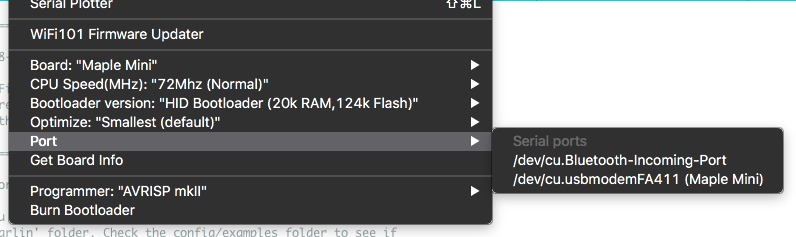
- ide
- arduino.png (56.33 KiB) Viewed 568 times
Now, the HID bootloader seems to work perfect on Windows, Linux and MacOSX
I hope tomorrow I will upload the patch and the source code to the Github repo.
BTW.
I Installed MINgW so I can compile hid-Flash.exe but I have not had time to try compiling it yet
I read that you sent a PR with some changes in the Arduino_STM32 repo. I will download the latest version to see if the HID bootloader works properly.
I pushed some changes, to remove the code for the “robotis” bootloader (no one seems to know what this bootloader is / was.
I’ve also removed the code that resets when the terminal is set to 1200 baud, as that also seems to be for the robotis bootloader.
@victor_pv has recommend some other changes to make the code cleaner, but I’ve not done those yet.
Under Windows it works very well. Under Linux it does not work neither the hid bootloader nor the bootloader 2.0 (maple DFU). The led blinks very fast.
Vassilis
When you say the LED blinks fast..
Do you think the code is crashing in the core and not jumping to the bootloader ??
The best thing to do is get the core to set a GPIO pin to HIGH just before it jumps to the bootloader, and monitor that GPIO with a logic analyser
If the GPIO pin high but the core does not jump to the bootloader, there must be some difference in the Gcc on Linux
It’s possible that the reset on Linux was only happening before because of rhe WDT, but this just means the reset code need to be bug fixed
I will try the LED trick you mentioned earlier.
Ok. I took that bootloader challenge, personal (because I like solving puzzles) and finally, I did it.
After Roger made some changes in usb_serial.cpp file (and some other files too) I had been working for a few days and finally I made the HID bootloader work perfect on the 3 platforms (Windows, Linux and MacOS. So, the HID bootloader works great now!
Works now with the known sequence 1EAF + DTR + RTS
I didn’t stop there. I made the bootloader2.0 to work ok on the 3 platforms too ! A few changes have made, mostly in batch files.
So, now these two bootloaders work perfect on the 3 OS platforms ![]()
I need some time to re-pack all the files and upload them to the Github.
OK it seems to work, at least in my linux machine, autoreset is working always (20 to 20 success). At last I enjoy the autoreset function in my machine!!!
I see a difference in usb_serial.c, in the rxHook function in searching for “magic 1EAF”. Now you buffer locally entire rx buffer and check the last 4 bytes for “1EAF”, nice, it costs some bytes but seems more safe…
I personally prefer a more safe way for signaling the reset sequence without “magic bytes” and buffer searching in the receive routine which costs time and memory, for example a specific sequence of DTR/RTS is a better way, but anyway leaflabs decided this way…
I test it also without the USB-CDC support in the core or with the BOOT1=1 (staying in the bootloader), but the hid-flash failed, as there was not any serial port.
Trying to open the comport...

error, counldn't open comport  /dev/ttyACM0

Sending <reset pages> command...

Error while sending <reset pages> command.

Error while sending <reset pages> command.
[Slammer – Wed May 23, 2018 12:46 am] –
I test it also without the USB-CDC support in the core or with the BOOT1=1 (staying in the bootloader), but the hid-flash failed, as there was not any serial port.
Trying to open the comport...

error, counldn't open comport  /dev/ttyACM0

Sending <reset pages> command...

Error while sending <reset pages> command.

Error while sending <reset pages> command.
Vassilis
I just tried the original version of the bootloader that @bootsector wrote,
https://github.com/bootsector/stm32-hid … r/releases
And it does show up correctly on my Windows 7 machine
So either something you changed in the code, or possibly the compiler version you are using, mean it does not reliably show up on my different machines
I doubt if I will be the only person where the bootloader does not work on their machine. Lots of people still use Windows 7 and Windows 8 etc
I tried to integrate the USB HID Bootloader with Arduino_Core_STM32.
I’m able to compile and flash by moving boot1 jumper with the STM32Druino library and Arduino_Core_STM32
With Arduino_Core_STM32, after it’s flashed, my program wont execute (I tried also with the blink app and nothing).
I’m pretty sure it’s related to the linker script. The only change I made is:
FLASH (rx) : ORIGIN = 0x08001000, LENGTH = 60K
Is there something else I should do? I didn’t use the hid_bootloader.ld file.
You can check my commit here: https://github.com/Suprazz/STM32CoreHID … 2fe9b74428
In another thread I proposed to enable the internal pull-down on PB2 pin (BOOT-1). That will help in case someone wants to force the Bluepill stay in bootloader. There is a small problem on that.
Setting PB2 to pull-down
The Bluepill PCB has a 100k resistor (R4) between BOOT-1 jumper and PB2 pin. That means, when I set that pin to pull-down and the jumper is out of the connector, the PB2 has 0V. That is ok. When I connect the BOOT-1 jumper to 3.3V, the PB2 has only 0.95V. That is happening because the R4 and the internal pull-down resistor act as a voltage divider.
Of course, 0.94 V is not enough to set the PB2 at Logic ‘1’.
Setting PB2 to pull-up
When I set that pin to pull-up and the jumper is out of the connector, the PB2 has 3.3V. That is ok. When I connect the BOOT-1 jumper to 0V, the PB2 has 2.18V that is too high to be considered as Logic ‘0’
Blackpill does not seems to have that problem because it uses 10k resistor.
There are some possible solutions
- Replace the R4 (or add in parallel an additional resistor) with a smaller value resistor (10 – 20k). [It needs soldering skills]
- Short-circuit the R4 with a small wire. [It needs soldering skills too…]
- Let the PB2 as-is. Now it is in Floating mode [That would be a problem with other boards like MapleMini, that the PB2 is not connected to +3.3V or 0V]. One finger touch of that pin could force the MCU to enter in bootloader during reboot.
- The Bluepill setup can be left in floating mode but it will require the BOOT-1 jumper to be either at 3.3V or at 0V. The internal pull-down can be enabled to the other boards like MapleMini.
Option 4 seems to me more logical
I would also agree with nr. 4.
I will test the magical “finger touch” workaround on my board.
I searched and searched and found nothing.
I’m able to flash my board with the HID bootloader, but if the program is compiled with the modified linker script (with the right address) it doesn’t execute. If I put the jumper Boot1, i can start the HID Bootloader again and flash again.
Not sure what else to verify. I look at the linkerscript files and I cannot see anything else that would affect that…
[Suprazz – Sun Jun 03, 2018 2:17 am] –
I tried to integrate the USB HID Bootloader with Arduino_Core_STM32.I’m able to compile and flash by moving boot1 jumper with the STM32Druino library and Arduino_Core_STM32
With Arduino_Core_STM32, after it’s flashed, my program wont execute (I tried also with the blink app and nothing).
I’m pretty sure it’s related to the linker script. The only change I made is:
FLASH (rx) : ORIGIN = 0x08001000, LENGTH = 60KIs there something else I should do? I didn’t use the hid_bootloader.ld file.
You can check my commit here: https://github.com/Suprazz/STM32CoreHID … 2fe9b74428
[Suprazz – Wed Jun 06, 2018 12:02 am] –
I searched and searched and found nothing.I’m able to flash my board with the HID bootloader, but if the program is compiled with the modified linker script (with the right address) it doesn’t execute. If I put the jumper Boot1, i can start the HID Bootloader again and flash again.
Not sure what else to verify. I look at the linkerscript files and I cannot see anything else that would affect that…
[Suprazz – Sun Jun 03, 2018 2:17 am] –
I tried to integrate the USB HID Bootloader with Arduino_Core_STM32.I’m able to compile and flash by moving boot1 jumper with the STM32Druino library and Arduino_Core_STM32
With Arduino_Core_STM32, after it’s flashed, my program wont execute (I tried also with the blink app and nothing).
I’m pretty sure it’s related to the linker script. The only change I made is:
FLASH (rx) : ORIGIN = 0x08001000, LENGTH = 60KIs there something else I should do? I didn’t use the hid_bootloader.ld file.
You can check my commit here: https://github.com/Suprazz/STM32CoreHID … 2fe9b74428
Does this repo support SerialUSB ?
[Suprazz – Wed Jun 06, 2018 12:02 am] –
I searched and searched and found nothing.I’m able to flash my board with the HID bootloader, but if the program is compiled with the modified linker script (with the right address) it doesn’t execute. If I put the jumper Boot1, i can start the HID Bootloader again and flash again.
Not sure what else to verify. I look at the linkerscript files and I cannot see anything else that would affect that…
The minimum modifications you have to do to enable the HID-BL are:
Replace in platform.txt file
OLD: compiler.c.flags={compiler.extra_flags} -c {build.flags.optimize} {compiler.warning_flags} -std=gnu11 -ffunction-sections -fdata-sections -nostdlib --param max-inline-insns-single=500 -Dprintf=iprintf -MMD {compiler.stm.extra_include}
NEW: compiler.c.flags={compiler.extra_flags} -c {build.flags.optimize} {compiler.warning_flags} -std=gnu11 -ffunction-sections -fdata-sections -nostdlib --param max-inline-insns-single=500 -Dprintf=iprintf -MMD {compiler.stm.extra_include} -D{build.vect}
I was hoping to use this bootloader because I have trouble enumerating the /dev/ttyACM0 serial device, and I can only program if I hit the reset button at just the right time.
I flashed to my blue pill with HIDBOOTLOADER.bin, both from the release on github, and I compiled it as well. I don’t get any usb device despite the boot jumpers. Only usb read descriptor errors.
When I flash back generic_boot20_pc13.bin, I get a usb device, but it’s very difficult to use because it doesn’t enumerate /dev/ttyACM0 properly until it flashes the first time, and that requries resetting at just the right time.
+100!
@Vassilis, please let me know if you need help, I am volunteering for testing the HID bootloader on my black F4VET6 board and the mini F4VET6 board.
Btw, the latest hid-flash utility for F1 waits again several (more than necessary) seconds to detect the HID device after reset. This was quicker by the previous version. Would it be possible to reduce this detection time again?
I am missing those ‘#’ characters from here. viewtopic.php?f=32&t=3661&start=80#p46036
[stevestrong – Thu Jun 21, 2018 1:21 pm] –
@Vassilis, please let me know if you need help, I am volunteering for testing the HID bootloader on my black F4VET6 board and the mini F4VET6 board.
ok, thanks
[stevestrong – Thu Jun 21, 2018 1:21 pm] –
Btw, the latest hid-flash utility for F1 waits again several (more than necessary) second to detect the HID device after reset. This was quicker by the previous version. Would it be possible to reduce this detection time again?
I am missing those ‘#’ characters from here. viewtopic.php?f=32&t=3661&start=80#p46036
I will check this out.
do you have an initial version for F4 to test? Any source on git?
Could you improve the speed of hid-flash to recognize the device?
[stevestrong – Fri Jul 06, 2018 10:04 am] –
Hi Vassilis,
do you have an initial version for F4 to test? Any source on git?
Could you improve the speed of hid-flash to recognize the device?
I wrote from scratch the F4 HID bootloader (HID-BL) by using the cubemx. The produced .bin file is almost 12 kB but this is not a problem because the STM32F407 has at minimum, 16 kB flash memory page (sector) size (the stm32f103 has 1kB page size).
I also wrote the F1 HID BL by using cubemx but the .bin file is almost 10kB. Too big for a 64 kB MCU. I am trying to reduce the size but the cubemx it is known that produces big .bin files (bloated code).
I adapted the hid-flash file to work on both F1 and F4 bootloaders but on the new cubemx binaries.
The current hid-flash file has a small problem. The software sends the flash page and then delays some micro seconds to let the mcu burn the flash page to the flash memory. The delay time is estimated and is causing a bigger delay to the flash process. What I did is to send the flash page from the computer to the mcu, the mcu burns the flash page and responds with a “write success” command. When the hid-flash receives that response, sends the next flash page. That minimizes the total flash process time.
I am sorry for this delay but I don’t have too much free time to work on HID-BL because my job is very demanding.
When I have any further news I will inform you.
The new firmware supports the Bluepill and Black 407VE boards. The new hid-flash tool works only on the newest HID-BL firmware and only on Windows. Linux and MacOS versions will be available next week (maybe sooner).
The HID-BL is appeared as “HID Bootloader 2.0” on the Arduino IDE menuThe source code for the 407 boards is not uploaded yet. Only 2 binaries with LED on PB3 or PE0 pins. [Edit] To put the 407 board in forced hid bootloader mode, put the PD15 pin LOW. Normally, the PD15 has to be in HIGH state (through a 1 to 10k resistor) during mcu reboot. I did that because the ArchMax v1.1 board does not have the BOOT-1 pin available to the pin header.
It works perfect on ArchMax v1.1 and diymore stm32f407 board
[/edit]
The HID-BL is available on Arduino_STM32 and STM32GENERIC repositories. I sent both pull requests.
Great work! Just to confirm what are the necessary stepr to get this working on BluePill ?
Here’s what I’ve done:
– flashed hid_generic_pc13.bin with ST-Link.
– downloaded latest Arduino_STM32
– applied this patch: Arduino_STM32_patch_180610_02.zip
So when flashing I’m currently getting this error:
> Trying to open the comport...

> Toggling DTR...

> Searching for 1209:BEBA HID device...

> 1209:BEBA device is found !

> Sending <reset pages> command...

> Error while sending <reset pages> command.

> Error while sending <reset pages> command.
Michael, the patch 180610_02 contains the old hid-flash.exe tool. Replace the old hid-flash.exe with the new one (v2.0) from here
I will make a new patch that is for HID-BL v2.0 and above.
Tested v2.0 on a black pill (hid-generic-pb12), Linux Mint 17.3. You are missing a space in the banner text (main.c, line 76).
+----------------------------------------------------------------------+

|         HID-Flash v2.0 - STM32 HID Bootloader Flash Tool            |

|     (c) 04/2018 - Bruno Freitas - http://www.brunofreitas.com/       |

|     (c) 04/2018 - Vassilis Serasidis - http://www.serasidis.gr/      |

|   Customized for STM32duino ecosystem - http://www.stm32duino.com/   |

+----------------------------------------------------------------------+
> Trying to open the comport...
> Searching for 1209:BEBA HID device...
#
> 1209:BEBA device is found !
> Sending <reset pages> command...
> Flashing firmware...
. 1024 Bytes
. 2048 Bytes
. 3072 Bytes
. 4096 Bytes
. 5120 Bytes
. 6144 Bytes
. 7168 Bytes
. 8192 Bytes
. 9216 Bytes
. 10240 Bytes
. 11264 Bytes
. 12288 Bytes
. 13312 Bytes
. 14336 Bytes
. 15360 Bytes
> Done!
> Sending <reboot mcu> command...
Ok. Thanks for testing the new version
[Vassilis – Thu Aug 09, 2018 2:01 pm] –
Michael, the patch 180610_02 contains the old hid-flash.exe tool. Replace the old hid-flash.exe with the new one (v2.0) from hereI will make a new patch that is for HID-BL v2.0 and above.
Yep, thanks. 2.0 version works with my BluePill.
> Trying to open the comport...

> Toggling DTR...

> Searching for 1209:BEBA HID device...

##

> 1209:BEBA device is found !

> Sending <reset pages> command...

> Flashing firmware...

. 1024 Bytes

. 2048 Bytes

. 3072 Bytes

. 4096 Bytes

. 5120 Bytes

. 6144 Bytes

. 7168 Bytes

. 8192 Bytes

. 9216 Bytes

. 10240 Bytes

. 11264 Bytes

. 12288 Bytes

. 13312 Bytes

. 14336 Bytes

. 15360 Bytes

. 16384 Bytes

. 17408 Bytes
> Done!
> Sending <reboot mcu> command...
https://github.com/Serasidis/STM32_HID_ … tloader_F4
The small USB HID bootloader is getting even smaller!
While the USB HID bootloader version for STM32F4 using the bloated STM’s LL+HAL hardly fits into 16 KB (less important, since on STM32F4xx devices, the Flash page size is 16 KB anyway), @bootsector and @Vassilis were able to generate an STM32F1xx version that works within 4 KB only, thus leaving 60 KB/124 KB for the user application, thanks to a lean bare-metal / CMSIS-based USB driver implementation.
Now, by applying a fair amount of optimization techniques (still using C gnu99, no assembly), I was able to reduce the bootloader size from 4KB down to 2 KB ![]()
My Github Pull Requests have been accepted by @Vassilis, so the new version is readily available in the previous HID Bootloader repository:
https://github.com/Serasidis/STM32_HID_Bootloader
Using this new USB HID bootloader version 3.0, the user application now comfortably has 62 KB / 126 KB left in Flash memory on the STM32F1xx, while still supporting the same bootloader functionalities :
- Enter the bootloader by forcing the BOOT1 (PB2) pin low
- Arduino API’s magic word detection in battery backed-up memory / DTR toggling to force USB re-enumeration from USB CDC and entering the bootloader after reboot (this avoids having to move a jumper if a bootloader-aware application is running)
- Invalid user application detection (no initial stack pointer) to stay in bootloader
- “nervous” LED blinking to distinguish it from the standard Blink sketch

Here is the motivation for this work: I already knew both the USB protocol and bare-metal ARM Cortex M3 programming on other MCUs (EFM32 and LPC11/LPC13…), but so far I only used the STM32 using the Arduino API, and I wanted to explore bare-metal programming on the STM32 and understand register-level USB implementation. I can now say that these goals have been reached.
Although the result in itself is interesting for end-users, the journey to get there is at least as interesting too: the different commits show various optimization techniques that were used to achieve this result, including in no particular order:
- Optimized Processor Vector Table handling with an initial (minimal) table during early boot, intermediate table for USB bootloader, and final table from the user application
- Removed of all redundant code enforcing hardware register initial boot values, since, hey, we ARE already a primary bootloader, so we can count on these! Basically, this get rid of a large part of the SystemInit() and SetSysClock() functions in “bootloader_F1/CMSIS/Device/ST/STM32F10x/Source/Templates/system_stm32f10x.c”
- Replaced inline assembly by the corresponding CMSIS macros
- Used STM’s CMSIS CLEAR_BIT(), SET_BIT(), READ_REG(), WRITE_REG() macros for peripheral register register access everywhere
- Code logic optimization
- Removed all initialized data: turn them either to const or uninitialized data; explicitely initialize data in the code whenever needed, so there is no need to initialize either .data section from initial values in Flash or .bss section to zero in early boot code in ResetHandler() from “bootloader_F1/CMSIS/Device/ST/STM32F10x/Source/Templates/gcc/startup_stm32f10x_md.s”
- Removed dependency on standard libraries, so C++ exception and static constructors / destructors bloat in ResetHandler() are not pulled in
- Used OPTIMAL macros to access the USB peripheral registers, including TOGGLE_REG() for registers using the brainf*** “toggle bits” feature
- Turned all possible variable functions to a local scope (e.g. “static”) whenever possible, so the compiler can further optimize code, like placing called-once function inline
- Turned off compiler feature to place each and every variable / function in a separate section: even if it usually helps to get rid of unused data / code when using the corresponding linker’s automatic section garbage collect, this actually prevents the compiler to perform section-level optimization, such as sharing constant pools and avoiding unnecessary alignment holes
- Replaced LED and GPIO declarations and functions by optimized macros: no need to get a call function overhead just to toggle a bit
- Avoid repeating the same function call with different arguments in a switch statement: replaced them with setting the correct arguments in each case and call the function only once at the end
If asked, I can further explain the optimizations, the early boot code sequence or the USB peripheral access.
+1
Great work!
If you’re feeling like another project, a PR for STM’s core would be great too ![]()
[BennehBoy – Sun Jan 20, 2019 11:15 am] –
Great work!If you’re feeling like another project, a PR for STM’s core would be great too
LL+HAL is such a bloat, I wonder if it is not better to start from scratch?
If it were not the license, libopencm3 would be a good start.
Maybe it is bloat, but on F4 I don’t think it matters much.
I’ll have a pop at a PR this afternoon – looking at the STM32GENERIC PR it doesn’t look like it will be too difficult – especially now that Frederic added pre-processing of the linker scripts.
[Squonk42 – Sun Jan 20, 2019 10:44 am] –
The small USB HID bootloader is getting even smaller!
Nice work Squonk42!
While I’m not a big fan of user written bootloaders, this one is nice and small and because of HID doesn’t even need to muck about with drivers. I like approach of just using the STM device header and then directly manipulating the registers. I’ve been using that in some of my code and it produces nice small code. Interesting that gcc does literal pooling, learn something new every day. I have seen some people leave the function call garbage collection on and turn off the data section gc. I guess the literal pool is why.
I did a bootloader for the msp430 in the past. One thing I did to make it easier on the users, the bootloader code silently rewrote their reset vector address and replaced it with the bootloaders address. This meant they didn’t have to muck about with the linker scripts to relocate their code past the bootloader. I would squirrel away the real user reset vector address and that is what the bootloader jumped to. For this HID bootloader, it seems like the hid-flash code could rewrite the 0x08000004 address and then send a new custom USB HID command to that tells the bootloader where the real address is so it could save it someplace in flash. Probably more of hassle than it is worth. However, then I could just take a normal binary and load it without having to recompile it. Of course for all this to work, the bootloader would have to be moved to the top of flash memory.
Great work, this seems to me the way to go for the future. This approach would fit nicely in the new ST core with a minimum of fuss.
Thanks!
Thank you Rick!
As it was at the same time my learning tool, I tried to tidy up the sources as much as I could while reading them, so I guess they will also be easier to read than they used to be.
As for the literal pooling, gcc tries to avoid absolute MOV instructions and replace them with LDR relative to PC, using literal pools placed at the end of each function. When using static functions and avoiding splitting them into different sections, gcc is able to inline them and remove even more duplicates in the combined literal pool if you don’t use the “-ffunction-sections” and “-fdata-sections” options. You can leave the linker option “-Wl,–gc-sections” though, as it will still eliminate whole sections of data or code that are not used at all.
Also, not using the “-ffunction-sections” and “-fdata-sections” options has the benefit of allowing the compiler to pack functions without a forced realignment between each atomic section, saving a few bytes here and there.
Regarding silently rewriting the user’s reset vector address, I must say that I thought about it, leaving the user’s application at the beginning of the Flash region and placing the tiny bootloader at the end of it, modifying the user’s reset vector to point to the boootloader, that would have to store somewhere the original user vector address to call it back upon bootloader exit. My self-objections were:
- If the user’s application is modified, it cannot be signed
- The original user reset vector has to be stored somewhere to jump back to the user application: I thought of using the option bytes, but there are only 2 of them. As ARM Thumb code addresses are always odd, we could shift the original address right one bit when storing it and back left when jumping to it, so we could cover the 128 KB Flash range. But it doesn’t scale well for larger Flash sizes
- Instead of storing the original user reset vector in the option bytes, we could create a small stub at the end of the user code to where the modified boot vector jumps, call the bootloader from there and jump back to the original user reset vector address upon bootloader exit: right now, this must be done using the 48 byte code that I have left

Any idea is welcome!
I am still working on this bootloader to improve it further.
My current job is to replace the awkward pin configuration by something like “#define LED1 PC13” and compute all the required registers and values using pre-processor macros; if possible pooling multiple GPIO definitions in the same configuration registers.
This first one should not be too difficult, but the second one is more involved, as it touches the overall structure of the bootloader.
Right now, the main process calls the USB init() and USB_Shutdown() functions in the USB driver generic layer from “usb.c” (this used to be using a dynamic linking with function pointers that was not very useful).
This generic driver then calls in turn the HID layer from “hid.c” using the USB_Reset() and USB_EPHandler() functions to initialize the device and handle incoming “OUT” data coming from the host, the outcoming “IN” data being handled by the USB_SendData() function in the generic layer.
However, there is no clean separation between the HID layer and the loader layer that eventually calls the flashing function FLASH_WritePage()…
Actually, the HIDUSB_HandleData() function should be somewhere out of “hid.c” (in a new “loader.c”?), and the part of the USB_EPHandler() function that deals with SETUP packets should return to “usb.c”, as well as the generic HIDUSB_GetDescriptor() function. Then, what is left in “hid.c” are basically the HID specific descriptors and the specific HID endpoint init in USB_Reset().
And the whole design is kind of upside-down: the main process should call the loader, which should call the HID layer, which in turn should call the generic USB layer in a top-down way. By cleanly splitting the main loop, the loader, HID and USB layers, it would then become easy to replace a given implementation by a new one, e.g. replace the HID by DFU, CDC or MSC (the loader will be different too, as the commands are not compatible), or do something else than a loader based on the HID (mouse + keyboard…).
Last, I wanted to replace the built-in outdated CMIS by a dynamic git submodule to the latest STM’s CMSIS definition, automatically extracted from the up-to-date CMSIS device headers from STM using a Travis CI process:
https://github.com/modm-io/cmsis-header-stm32
[Squonk42 – Sun Jan 20, 2019 4:07 pm] –
Regarding silently rewriting the user’s reset vector address, I must say that I thought about it, leaving the user’s application at the beginning of the Flash region and placing the tiny bootloader at the end of it, modifying the user’s reset vector to point to the boootloader, that would have to store somewhere the original user vector address to call it back upon bootloader exit. My self-objections were:
- If the user’s application is modified, it cannot be signed
- The original user reset vector has to be stored somewhere to jump back to the user application: I thought of using the option bytes, but there are only 2 of them. As ARM Thumb code addresses are always odd, we could shift the original address right one bit when storing it and back left when jumping to it, so we could cover the 128 KB Flash range. But it doesn’t scale well for larger Flash sizes
- Instead of storing the original user reset vector in the option bytes, we could create a small stub at the end of the user code to where the modified boot vector jumps, call the bootloader from there and jump back to the original user reset vector address upon bootloader exit: right now, this must be done using the 48 byte code that I have left
Any idea is welcome!
I am still working on this bootloader to improve it further.
My approach (inspired by this original forum post) is to make use of some of the reserved slots in the vector table from offset 0x1C-0x2B. From my testing on the bluepill, there are no weird side-effects to stuffing 8 bytes at offset 0x1C for the user’s reset vector address and initial stack pointer. This doesn’t solve the signing problem, but it does let you avoid using an extra flash page.
[Squonk42 – Sun Jan 20, 2019 4:07 pm] –
[*]Instead of storing the original user reset vector in the option bytes, we could create a small stub at the end of the user code to where the modified boot vector jumps, call the bootloader from there and jump back to the original user reset vector address upon bootloader exit: right now, this must be done using the 48 byte code that I have left
You might want to switch to a newer arm-none-eabi-gcc for smaller size. I’m using 7.3.1 and it ends up being 1984 text + 8 data bytes. This is even after I added _DMB() and _DSB() calls around the VTOR changes, and made the “uint32_t i” in delay a volatile. 56 bytes instead of 48 ![]()
[devan – Sun Jan 20, 2019 5:38 pm] –
My approach (inspired by this original forum post) is to make use of some of the reserved slots in the vector table from offset 0x1C-0x2B. From my testing on the bluepill, there are no weird side-effects to stuffing 8 bytes at offset 0x1C for the user’s reset vector address and initial stack pointer. This doesn’t solve the signing problem, but it does let you avoid using an extra flash page.
Yes, I was scared to use any of these “Reserved”, but this may be a solution. I don’t think we need to save the initial stack pointer though, we just need to setup ours in the temporary HID USB vector table before using the stack aren’t we?
[Rick Kimball – Sun Jan 20, 2019 5:52 pm] –[Squonk42 – Sun Jan 20, 2019 4:07 pm] –
[*]Instead of storing the original user reset vector in the option bytes, we could create a small stub at the end of the user code to where the modified boot vector jumps, call the bootloader from there and jump back to the original user reset vector address upon bootloader exit: right now, this must be done using the 48 byte code that I have leftYou might want to switch to a newer arm-none-eabi-gcc for smaller size. I’m using 7.3.1 and it ends up being 1984 text + 8 data bytes. This is even after I added _DMB() and _DSB() calls around the VTOR changes, and made the “uint32_t i” in delay a volatile. 56 bytes instead of 48
![]()
I was sticking to the 4.9.3 since it is the one packaged in my old Ubuntu 16.04 LTS, as it is already better than the one from the Arduino SAMD package, but I may follow your path here… Maybe we should agree on a common “official” version? Which one did you get and where from?
As for the _DMB() _DSB(), I though that in Cortex-M3, Cortex-M4, and Cortex-M0+ processors, a memory barrier was not required after a VTOR update:
http://infocenter.arm.com/help/index.js … HDGBC.html
I suggest that everyone sends PR to @Vassilis’s repo to keep in sync!
I am just looking at your MSP430 gdb bootloader, nice ![]()
[Squonk42 – Sun Jan 20, 2019 6:06 pm] –
Yes, I was scared to use any of these “Reserved”, but this may be a solution. I don’t think we need to save the initial stack pointer though, we just need to setup ours in the temporary HID USB vector table before using the stack aren’t we?
Yeah, I guess that’s true – in exchange for doing a little work to fixup the stack pointer in code, you can avoid overwriting the application’s initial stack pointer in flash. Then you only need to make room for four bytes.
[Rick Kimball – Sun Jan 20, 2019 5:52 pm] –
[…] I […] made the “uint32_t i” in delay a volatile. 56 bytes instead of 48
I am not sure this is required, since the NOP will prevent gcc from optimizing the loop : here is what I get without volatile :
08000008 <delay>:

8000008:	2300      	movs	r3, #0

800000a:	4283      	cmp	r3, r0

800000c:	d002      	beq.n	8000014 <delay+0xc>

800000e:	bf00      	nop

8000010:	3301      	adds	r3, #1

8000012:	e7fa      	b.n	800000a <delay+0x2>

8000014:	4770      	bx	lr
[Rick Kimball – Sun Jan 20, 2019 5:52 pm] –
You might want to switch to a newer arm-none-eabi-gcc for smaller size. I’m using 7.3.1 and it ends up being 1984 text + 8 data bytes. This is even after I added _DMB() and _DSB() calls around the VTOR changes, and made the “uint32_t i” in delay a volatile. 56 bytes instead of 48
… 1972 text + 8 data bytes using latest gcc from here:
https://developer.arm.com/open-source/g … /downloads
$ make generic-pc13

CLEAN

arm-none-eabi-gcc (GNU Tools for Arm Embedded Processors 8-2018-q4-major) 8.2.1 20181213 (release) [gcc-8-branch revision 267074]
Copyright (C) 2018 Free Software Foundation, Inc.

This is free software; see the source for copying conditions.  There is NO

warranty; not even for MERCHANTABILITY or FITNESS FOR A PARTICULAR PURPOSE.
mkdir build
CC Src/main.c
CC Src/usb.c
CC Src/hid.c
CC Src/led.c
CC Src/flash.c
LD build/main.o
Memory region Used Size Region Size %age Used
RAM: 3024 B 20 KB 14.77%
FLASH: 1980 B 64 KB 3.02%
GENBIN build/hid_bootloader.bin
COPY bootloader_only_binaries/hid_generic_pc13.bin
INFO build/hid_bootloader.elf
SIZE    build/hid_bootloader.elf

text	   data	    bss	    dec	    hex	filename

1972	      8	   3024	   5004	   138c	build/hid_bootloader.elf
[Squonk42 – Sun Jan 20, 2019 6:49 pm] –
SIZE build/hid_bootloader.elf
text data bss dec hex filename
1972 8 3024 5004 138c build/hid_bootloader.elf
[Rick Kimball – Sun Jan 20, 2019 7:37 pm] –
I’m on ubuntu, I use this repo https://launchpad.net/~team-gcc-arm-emb … ubuntu/ppa
After reverting my changes, so I’m in sync with your repo, mine comes out smaller (1956+8)
   text	   data	    bss	    dec	    hex	filename

1956	      8	   3024	   4988	   137c	build/hid_bootloader.elf
Yes, the official ST core will have to implement the same mechanism as Roger’s core to detect the “reboot in bootloader mode” sequence, i.e.:
- a negative edge on DTR before
- receiving the in-band magic reset byte sequence ‘1’, ‘E’, ‘A’, ‘F’
- store 0x424C (“BL”) in BKP->DR10
- actually perform a CPU reset
Here is the code in Roger’s core:
https://github.com/rogerclarkmelbourne/ … l.cpp#L248
Otherwise, the user will have to move the BOOT1 jumper every time the bootloader entry is required.
[Rick Kimball – Sun Jan 20, 2019 8:55 pm] –
Say we did want to use this with the official ST core? How are you going to deal with reset? I don’t think the usb cdc driver is looking for any magic characters.
I’ve written a PR which includes it…
I can upload and the board resets into the sketch, but after system reset it’s back to the bootloader permanently, not sure if I messed up or there’s an issue with the F4 bootloader…. (my money is on me)
Work in progress in my fork -> https://github.com/BennehBoy/Arduino_Co … BootLoader
You’ll also need this PR for the STM tools -> https://github.com/stm32duino/Arduino_Tools/pull/33 (or just drop hid_flash.exe into the tools/win folder)
I’ll submit it once I’ve tested F1 on STM’s core, but I need to tweak first.
[Rick Kimball – Sun Jan 20, 2019 8:06 pm] –
you have to change boards.txt and hid_bootloader.ld script to match
Hmm, what does the boot vector need to change to 0x8000800?
Yup, working, great.
Now to update my PR
F1 tested and working against STM core.
I’ll test F4 against Roger’s and see if I get the same issue.
Same behaviour with Roger’s core, flashes OK and resets into sketch, but after a further system reset it’s perpetual bootloader.
If this is not a problem with my compilation of the BL then I guess this is one for Vassilis. I’ll try a couple different flavours of gcc and see if there’s any difference in behaviour.
EDIT – used one of the supplied hex’s and still same behaviour after system reset ![]()
PS – if I then press ‘reset’ on the board, it executes the sketch – is this by design?
It is good for us to use the latest HID-BL version but the new release v3.0 on the Arduino IDE side is incompatible with the boards that are already supplied with HID-BL v2.0 because of the different Usercode area address (VECT_TAB_ADDR=0x8000800 instead of VECT_TAB_ADDR=0x8001000). That problem may confuse people that will try to use the v2.0 boards with the Arduino IDE that supports only v3.0. It is not good to fill the Arduino IDE with too many HID-BL versions. The last one is good enough.
For that reason I have made some modifications on both Firmware and software (hid-upload)
– Firmware side –
I have changed the Firmware revision to the USB_DeviceDescriptor to version 3.00
static const uint8_t USB_DeviceDescriptor[] = {

0x12,			// bLength

0x01,			// bDescriptorType (Device)

0x10, 0x01,		// bcdUSB 1.10

0x00,			// bDeviceClass (Use class information in the Interface Descriptors)

0x00,			// bDeviceSubClass

0x00,			// bDeviceProtocol

MAX_PACKET_SIZE,	// bMaxPacketSize0 8

0x09, 0x12,		// idVendor 0x1209

0xBA, 0xBE,		// idProduct 0xBEBA

0x00, 0x03,		// bcdDevice 3.00 <-----------------------------<<

0x01,			// iManufacturer (String Index)

0x02,			// iProduct (String Index)

0x00,			// iSerialNumber (String Index)

0x01 			// bNumConfigurations 1

};
[Vassilis – Mon Jan 21, 2019 7:13 pm] –
It is good for us to use the latest HID-BL version but the new release v3.0 on the Arduino IDE side is incompatible with the boards that are already supplied with HID-BL v2.0 because of the different Usercode area address (VECT_TAB_ADDR=0x8000800 instead of VECT_TAB_ADDR=0x8001000). That problem may confuse people that will try to use the v2.0 boards with the Arduino IDE that supports only v3.0. It is not good to fill the Arduino IDE with too many HID-BL versions. The last one is good enough.
Yet another reason to think about loading the bootloader in high memory instead of at the beginning of flash. You could have a 10k bootloader or a 250 byte one if you load it at the end. It wouldn’t matter to the user if they are loading their code at 0x08000000.
[Rick Kimball – Mon Jan 21, 2019 10:15 pm] –[Vassilis – Mon Jan 21, 2019 7:13 pm] –
It is good for us to use the latest HID-BL version but the new release v3.0 on the Arduino IDE side is incompatible with the boards that are already supplied with HID-BL v2.0 because of the different Usercode area address (VECT_TAB_ADDR=0x8000800 instead of VECT_TAB_ADDR=0x8001000). That problem may confuse people that will try to use the v2.0 boards with the Arduino IDE that supports only v3.0. It is not good to fill the Arduino IDE with too many HID-BL versions. The last one is good enough.Yet another reason to think about loading the bootloader in high memory instead of at the beginning of flash. You could have a 10k bootloader or a 250 byte one if you load it at the end. It wouldn’t matter to the user if they are loading their code at 0x08000000.
+1
I will definitely try to put the bootloader in high memory asap, this will avoid the multiplication of linker scripts for the different bootloaders.
[Rick Kimball – Mon Jan 21, 2019 11:03 pm] –
Of course the linker script would have to know the size and not try to use bootloader memory.
Well, the bootloader could check that its not self-erasing while flashing, so this error could be reported by the flashing tool rather by the linker, so we could avoid touching the linker script altogether…
I also rememnber some options for specifying the maximum sketch size in the board.txt or somewhere else in the Arduino files? This could be nice if it could be specified for this specific flashing tool only.
The new hid-flash executable is available for Windows, Linux and Mac@Rick
Thanks for the idea. I think that approach is complicated. I will try to test it though.
![]()
One very minor observation Vassilis, I compiled the F4 firmware to run on a Black407ZET6, BOOT1, PB2, LED, PF9 (or 10). The LED would not blink, I had a nose through the code and noticed the clock wasn’t being initialised for GPIOF, so added that and recompiled and still did not get a blinking LED. Any thoughts on what this could be?
PS the hid-flash executables don’t seem to be in the cli folder? Found them in the patch, oopsie
I will try to change the LED pin my 407 board and let you know
[BennehBoy – Tue Jan 22, 2019 10:22 am] –

One very minor observation Vassilis, I compiled the F4 firmware to run on a Black407ZET6, BOOT1, PB2, LED, PF9 (or 10). The LED would not blink, I had a nose through the code and noticed the clock wasn’t being initialised for GPIOF, so added that and recompiled and still did not get a blinking LED. Any thoughts on what this could be?
PS the hid-flash executables don’t seem to be in the cli folder? Found them in the patch, oopsie
1. Which repo do you use ?
2. Which variant do you use ?
3. Is the STM32 HID bootloader appeared in Windows device manager ?
4. Do you have a schematic of your board ?
5. Did you connect a LED to pin PF9 and is doesn’t blink during bootloader or after you upload the sketch to the STM32F407ZET ?
2. Black407ZET6
3. Yes
4. http://wiki.stm32duino.com/images/4/4f/ … _sch-1.pdf
5. PF9 & PF10 are the builtin LED’sI can blink both LED’s using standard blink.ino from within the core (or using Roger’s). LED’s don’t blink during bootloader.
Works fine for Black407VET6 or DIYMROE board, but these both have the LED(s) on GPIO A to E.
I recompiled the source code
LED -> PF9
BOOT1 -> PD6 (internal pull-up is enabled)
Tell me if it works
- HID-BL_407zet_LED-PF9_BOOT1-PD6.zip
- (10.22 KiB) Downloaded 7 times
[BennehBoy – Tue Jan 22, 2019 9:13 pm] –
We have a working LED though – did you change anything, or have I perhaps got a toolchain issue?
I didn’t change anything else than adding the clock for GPIOF
__HAL_RCC_GPIOF_CLK_ENABLE();
[Vassilis – Tue Jan 22, 2019 9:18 pm] –[BennehBoy – Tue Jan 22, 2019 9:13 pm] –
We have a working LED though – did you change anything, or have I perhaps got a toolchain issue?I didn’t change anything else than adding the clock for GPIOF
__HAL_RCC_GPIOF_CLK_ENABLE();
make -v

GNU Make 3.81

Copyright (C) 2006  Free Software Foundation, Inc.

This is free software; see the source for copying conditions.

There is NO warranty; not even for MERCHANTABILITY or FITNESS FOR A

PARTICULAR PURPOSE.
This program built for i386-pc-mingw32
https://github.com/stm32duino/Arduino_Core_STM32
During installation it downloads tools from here -> https://github.com/stm32duino/BoardManagerFiles
make -v

GNU Make 3.81

Copyright (C) 2006  Free Software Foundation, Inc.

This is free software; see the source for copying conditions.

There is NO warranty; not even for MERCHANTABILITY or FITNESS FOR A

PARTICULAR PURPOSE.
This program built for i386-pc-mingw32
In a first step to move the HID bootloader towards high memory, I sent a new PR to @Vassilis.
I changed the strategy to use USB polling instead of USB IRQs ![]()
Yeah, I know, usually it is the other way around, but the goal was to avoid creating the intermediate Vector Table in RAM just to add the USB IRQ handler: this way, the HID bootloader now only requires a minimal initial Vector Table in Flash to contain the Reset handler (PC) and the initial stack pointer (SP), even if we could live without this last one and set it first thing in the Reset handler routine itself.
This saves a couple more instructions (down to 1936 bytes total ![]() ), but OTOH we can no longer use blocking delay loops for blinking the LED. I used instead a static counter and toggled the LED using a bit mask, so the “nervous” blinking is still here, however at a probably slightly different frequency.
), but OTOH we can no longer use blocking delay loops for blinking the LED. I used instead a static counter and toggled the LED using a bit mask, so the “nervous” blinking is still here, however at a probably slightly different frequency.
The previous “USB_LP_CAN1_RX0_IRQHandler()” USB IRQ handler has become “USB_Poll()”, and the IRQ routing into the CMSIS core “NVIC_EnableIRQ()” has been removed, but everything else is untouched.
Overall, not creating yet another Vector Table is a good thing, and in the end the goal will be not to create one at all, but to modify the user’s one to jump to the HID bootloader and back to the application, so the SCB->VTOR core register will not be used, allowing the same bootloader to run on Cortex M0 MCUs (STM32F0xx) which do not feature this register too.
I also forced an USB_Shutdown()/USB_Init() cycle to perform an USB re-enumeration in all cases and not just when finding a magic word in the backup memory: I found it more convenient not having to physically disconnect/reconnect the USB cable when using the BOOT1 jumper or when there was no user application in memory.
I am not trying to make the bootloader smaller, this is just a consequence of making it simpler ![]()
Having the bootloader in high memory has absolutely no issue with the linker: the piece of code that is in charge of enforcing not to overwrite the BL is… The BL itself! We just need to control this during flashing.
And anyway, the maximum upload size can be hinted into the “board.txt”, for example:
mapleMini.menu.bootloader_version.hid_bootloader.upload.maximum_size=129024
[BennehBoy – Mon Jan 28, 2019 9:21 pm] –
For Bluepill for example, there will be 3 possible linker scenarios, 64KB, 128KB, 32KB (fake bluepill) Obviously just my 2 cents.
Maybe it would be easier to append the bootloader, this is approach you see on the PSOC devices.
OK, I have the HID bootloader working in high memory on the Bluepill. ![]()
Actually not a big deal, I just:
- Modified the linker script such that the bootloader is located 2KB below the top of the Flash memory (0x800F800 for a 64KB device)
- Started flashing at the beginning of the Flash rather than reserving 2 KB for the bootloader
- Before flashing the Page 0, patched the user vector table to save its reset handler @ address 0x4 to an unused vector address (0x1c) and write or own reset handler instead
- Checked that we do not overwrite ourselves (not writing pages > 62 for a 64KB device)
- Later fetched the user Reset handler from our saved location to hand over the CPU to the application firmware
- No longer modified the VTOR register
I just tested with a Blick sketch for the Serial (ROM) bootloader and this works OK, except that this sketch does not seem to write the magic word in backup memory, so I have to enter the bootloader by moving the BOOT1 jumper. I am not sure that the DTR+ LEAF patch is used in this configuration though, I will investigate tomorrow.
Current HID bootloader size is 1924 bytes text + 8 bytes data.
EDIT: I modified the board.txt and linker script to locate the sketch at 0x08000000 (beginning of Flash) and recompiled the sketch, everything is working as expected.
I will wrap things up and send a new PR.
Adding linker script preprocessing will make life easier on this, take a peep at STM’s core where this is added.
Here’s a section from the ldscript.ld being used for bluepill:
/* Entry Point */

ENTRY(Reset_Handler)
/* Highest address of the user mode stack */
_estack = 0x20000000 + LD_MAX_DATA_SIZE; /* end of RAM */
/* Generate a link error if heap and stack don't fit into RAM */
_Min_Heap_Size = 0x200; /* required amount of heap */
_Min_Stack_Size = 0x400; /* required amount of stack */
/* Specify the memory areas */
MEMORY
{
RAM (xrw) : ORIGIN = 0x20000000, LENGTH = LD_MAX_DATA_SIZE
#ifdef HIDBL_F1
FLASH (rx) : ORIGIN = 0x8000800, LENGTH = LD_MAX_SIZE - 0x800
#elif DFUBL2_F1
FLASH (rx) : ORIGIN = 0x8002000, LENGTH = LD_MAX_SIZE - 0x2000
#else
FLASH (rx) : ORIGIN = 0x8000000, LENGTH = LD_MAX_SIZE
#endif
}
Just see how you update LD script for bootloader size handling.
Would it be more simple to define a switch with bootloader size then this will avoid further update in case of new bootloader support?
FLASH (rx) : ORIGIN = 0x8000000 + BL_SIZE, LENGTH = LD_MAX_SIZE - BL_SIZE
With the bootloader in high memory, What happens if the application crashes ?
I can’t see how the MCU can enter the bootloader under those conditions.
[RogerClark – Fri Feb 01, 2019 8:56 pm] –
With the bootloader in high memory, What happens if the application crashes ?I can’t see how the MCU can enter the bootloader under those conditions.
What do you mean by “application crashes”? The bootloader replaces rhe application reset handler by its own upon flashing, and the CPU jumps to the bootloader first,thing after’boot, and calls the saved application reset handler upon exit. If the application crashes after this step, it does not’prevent entering the bootloader. Of course, the DTR + magic word in backup memory may not work under these conditions, but moving the BOOT1 jumper will.
The only case were you will not be able to enter the bootloader anymore is if you reflash the application by another mean (JLink or serial), but this case is not worse than with other bootloaders anyway.
The bootloader replaces the application reset handler
Ah.
You mean that bootloader modifies the application binary when it received it via HID to change the default reset handler location, so that when the board is reset, the code jumps to the bootloader’s address, i.e changes the “vector table”
So even if the application crashes, it doesn’t make any difference, unless the application corrupted the vector table (which is highly unlikely)
And the bootloader is not just loaded into the top of Flash memory, it also needs to contain the vector table – reset vector, to initially jump to the bootloader. Hence a raw binary file of the bootloader would need to be 128k for a STM32F103CB ?
Or use a firmware file format like which could have multiple sections ?
When there will need to be different bootloaders depending on the Flash size in the MCU. (32k, 64k, 128k etc)
Actually, this got me thinking about the large number of Maple bootloader variants, because of different LED pins and “user button” pins.
In theory, it should be fairly simple to write some sort of configurator program to change the LED pin and button pin by changing the binary file rather than having to maintain loads of different binaries.
However, the configurator would probably need to be modified if any changes where made to the code as it may not be possible for the configurator to automatically find which parts of the bin to change.
[RogerClark – Sat Feb 02, 2019 2:55 am] –
The bootloader replaces the application reset handlerYou mean that bootloader modifies the application binary when it received it via HID to change the default reset handler location, so that when the board is reset, the code jumps to the bootloader’s address, i.e changes the “vector table”
Yes, exactly!
The user’s original reset handler is backed up into one of the “reserved” vectors at offset 0x1C, as suggested above in this thread.
[RogerClark – Sat Feb 02, 2019 2:55 am] – And the bootloader is not just loaded into the top of Flash memory, it also needs to contain the vector table – reset vector, to initially jump to the bootloader. Hence a raw binary file of the bootloader would need to be 128k for a STM32F103CB ?Or use a firmware file format like which could have multiple sections ?
Yes, the bootloader contains 8 bytes (2 vectors) in low memory for a minimal Vector Table at addresses 0x0-0x7, containing an initial stack pointer (MSP) and the bootloader’s reset handler, and the resulting raw binary file then contains the whole device Flash. OTOH, if you use the Intel Hex (.ihex) format also supported by the st-flash utility, you get multiple sections and the Flash sectors are not contained into the much smaller file, although they are still erased and filled with 0xFFs if you read back the Flash memory with the same tool.
[RogerClark – Sat Feb 02, 2019 2:55 am] – When there will need to be different bootloaders depending on the Flash size in the MCU. (32k, 64k, 128k etc)Actually, this got me thinking about the large number of Maple bootloader variants, because of different LED pins and “user button” pins.
Yes, anyway, there are already many different bootloaders for the various device and board configurations.
[RogerClark – Sat Feb 02, 2019 2:55 am] – In theory, it should be fairly simple to write some sort of configurator program to change the LED pin and button pin by changing the binary file rather than having to maintain loads of different binaries.However, the configurator would probably need to be modified if any changes where made to the code as it may not be possible for the configurator to automatically find which parts of the bin to change.
Very good idea!
If you look at the “bootloader_F1/Inc/config.h”, there are not so many different options in practice, as the external resources required by the bootloader are quite limited:
- the input pin to force a bootloader entry (normally BOOT1/PB2) and if it requires to use an internal pull-up resistor or not, we could add a polarity
- the LED1 pin and probably its polarity too
- a currently unused LED2 pin
- the DISC output pin to drive an external USB disconnect circuit, again with a polarity
All other constants defined here can be derived from these settings.
If we drop support for LED2, we are left with the definition of only 3 pins. Given that GPIO ports range in theory from A to G and pins within these ports from 0 to 15, each GPIO could be stored in packed format into 7 bits. Polarity would require 1 additional bit, and the input pin a 1-bit pull-up flag. All this could probably be stored efficiently in approximately 3 bytes or less if we limit the possible GPIO ports.
We could used the same trick as when storing the user’s reset handler in a “reserved” vector table entry, or possibly use the 2 available options bytes in Flash memory Information Block at addresses 0x1FFF F800 – 0x1FFF F80F, although the handling of these bytes requires a significant amount of code.
[RogerClark – Sat Feb 02, 2019 2:55 am] – When there will need to be different bootloaders depending on the Flash size in the MCU. (32k, 64k, 128k etc)
Actually I checked the generated assembly code, and all the code is relative to PC, except for the Reset_Handler Vector Table entry.
This means that the HID bootloader is actually PIC (Position Independent Code) and could in theory be relocated anywhere in Flash memory, provided the low-memory Vector Tables points to it (the Reset_Handler entry point is the first location in high-memory).
We could thus generate a single .bin file that is independent of the Flash memory size to be placed in high-memory, and another small .bin files to be placed in low-memory containing the correct Reset_Handler for this device and possibly the configuration bytes I suggested in my previous post.
EDIT: code is PC-relative, but there is some absolute data ![]()
https://github.com/Serasidis/STM32_HID_ … der/pull/7
Use of the reserved vectors is an interesting idea.
My only concern is that adding code to read the data in the reserved vector, may make the bootloader bigger, beyond a flash page boundary.
But I suppose that since its now in high memory, then the size trade off for increase flexibility is probably worthwhile.
[Squonk42 – Sat Feb 02, 2019 11:10 pm] –
I amended the PR to @serasidis with the changes to put the HID bootloader in high-memory for the STRM32F1xx:
https://github.com/Serasidis/STM32_HID_ … der/pull/7
Will the core’s need to be updated ?
Since the application code will need to have its start address (of the vector table), at 0x800000
Or do you think that the cores may generate position independent code ?
( My guess is that the code is not guaranteed to be position independent)
BTW.
I remember that @jcw aka JeeLabs write a serial bootloader that resided in high memory, but I think he abandoned it for some reason (but perhaps he is still using it and developing it).
You could PM him, as he used to be active on the forum several years ago
[RogerClark – Sun Feb 03, 2019 12:51 am] –
Use of the reserved vectors is an interesting idea.My only concern is that adding code to read the data in the reserved vector, may make the bootloader bigger, beyond a flash page boundary.
But I suppose that since its now in high memory, then the size trade off for increase flexibility is probably worthwhile.
Using the latest GCC 8.2.1 from ARM Ltd. (Version 8-2018-q4-major Linux 64-bit), the bootloader size is currently 1924 bytes in high-memory, plus 8 bytes for the initial MSP and PC in low-memory, so there is 124 bytes left in high-memory before reaching the 2KB (2048 bytes) page boundary, which should be more than enough.
[RogerClark – Sun Feb 03, 2019 12:59 am] –
[Will the core’s need to be updated ?Since the application code will need to have its start address (of the vector table), at 0x800000
Or do you think that the cores may generate position independent code ?
( My guess is that the code is not guaranteed to be position independent)
The HID bootloader contains a ZIP file to patch your core, and this PR contains a new updated one, and @BennehBoy send a PR to integrate it into the STM Core:
https://github.com/stm32duino/Arduino_C … 2/pull/415
Basically, this patch replaces the “board.txt”, “platform.txt” to add the HID bootloader, includes the “usb_serial.cpp” with the DTR + magic word, and adds the linker scripts to match the bootloader memory organization.
It would be great to update your core, but maybe wait a little bit more until the HID bootloader is more stable?
I don’t think the core will need to generate PIC, but having a different file for each bootloader is a pain. We could take @BennehBoy and @fpiSTM idea and perform linker script preprocessing in the “platform.txt” file:
# preprocess linker file

preprocld.name=preproc.ld

preprocld.filepath={build.path}/{preprocld.name}

preprocld.flags=-DLD_MAX_SIZE={upload.maximum_size} -DLD_MAX_DATA_SIZE={upload.maximum_data_size}

recipe.hooks.linking.prelink.1.pattern="{compiler.path}{compiler.c.cmd}" -x c -E -P {preprocld.flags} {compiler.c.flags} {build.info.flags} {compiler.c.extra_flags} {build.extra_flags} {compiler.arm.cmsis.c.flags} "{build.variant.path}/{build.ldscript}" -o "{preprocld.filepath}"
Can I merge this PR before your PR to the bootloader is merged?
BTW. I think I may need to manually merge platform.txt as Ive just changed platform.txt to fix a bug with stlink uploads.
Edit.
I got confused, I thought the PR was for my core, but when I looked in detail, I saw its the STM core.
So I’ll need to find the zip file you referenced, to see what the patch does
Edit.
Where is this zip
Can you post a link ?
Edit
I found it
I’ve added and updated the files in the tools folder.
Note. The Mac binary was not marked as executable, so I’ve changed it to executable on my Linux machine. But this does not guarantee the permissions will work on the Mac. I’d need to pull the repo onto my mac and confirm this, but perhaps someone who regularly uses a mac can check this
[Squonk42 – Mon Feb 04, 2019 5:42 am] –
I am Linux only, I asked @serasidis to update the tools and fix the permission problem too.
I have Windows, Linux and OSX machines, but I hardly ever use OSX, I only have OSX to do builds for work clients.
I’ll manually merge the changes to boards.txt and platform.txt using my Windows (7) PC later today.
Looking at the github repo, all but the maple_mini version appear to be geared toward 64KB flash.
For now I guess this means that those with 32KB or 128KB flash devices will need to be capable of editing/supplying the correct linker script, modifying the makefile, and re-compiling.
Are pre-compiled binaries for the above on the roadmap?
I’m just thinking of how noobies might hit issues that high mem introduces.
Maple mini should always have 128k, but of course vendors could just rebadge C6 MCU’s as CB’s ![]()
One other thing that you may have already considered with the high memory bootloader is conflicts with the EEPROM library which also uses high memory.
#ifndef EEPROM_PAGE_SIZE

#if defined (MCU_STM32F103RB)

#define EEPROM_PAGE_SIZE	(uint16)0x400  /* Page size = 1KByte */

#elif defined (MCU_STM32F103ZE) || defined (MCU_STM32F103RE) || defined (MCU_STM32F103RD)

#define EEPROM_PAGE_SIZE	(uint16)0x800  /* Page size = 2KByte */

#else

#error	"No MCU type specified. Add something like -DMCU_STM32F103RB to your compiler arguments (probably in a Makefile)."

#endif

#endif
#ifndef EEPROM_START_ADDRESS
#if defined (MCU_STM32F103RB)
#define EEPROM_START_ADDRESS ((uint32)(0x8000000 + 128 * 1024 - 2 * EEPROM_PAGE_SIZE))
#elif defined (MCU_STM32F103ZE) || defined (MCU_STM32F103RE)
#define EEPROM_START_ADDRESS ((uint32)(0x8000000 + 512 * 1024 - 2 * EEPROM_PAGE_SIZE))
#elif defined (MCU_STM32F103RD)
#define EEPROM_START_ADDRESS ((uint32)(0x8000000 + 384 * 1024 - 2 * EEPROM_PAGE_SIZE))
#else
#error "No MCU type specified. Add something like -DMCU_STM32F103RB to your compiler arguments (probably in a Makefile)."
#endif
#endif
https://github.com/Serasidis/STM32_HID_ … der/pull/7
I revert the previous HID-BL version on Github because we first need to talk about what we want from this Bootloader for all MCU devices that we want to support and how to handle the best code strategy to do that.
For example, the F40x and F41x devices have 128kB at the last sector. That means, we sacrifice a lot of flash memory for the bootloader.
[RogerClark – Mon Feb 04, 2019 9:24 am] – Maple mini should always have 128k, but of course vendors could just rebadge C6 MCU’s as CB’s
Or C8s that are actually CBs ![]()
[RogerClark – Mon Feb 04, 2019 9:24 am] – One other thing that you may have already considered with the high memory bootloader is conflicts with the EEPROM library which also uses high memory.
#ifndef EEPROM_PAGE_SIZE
#if defined (MCU_STM32F103RB)
#define EEPROM_PAGE_SIZE (uint16)0x400 /* Page size = 1KByte */
#elif defined (MCU_STM32F103ZE) || defined (MCU_STM32F103RE) || defined (MCU_STM32F103RD)
#define EEPROM_PAGE_SIZE (uint16)0x800 /* Page size = 2KByte */
#else
#error "No MCU type specified. Add something like -DMCU_STM32F103RB to your compiler arguments (probably in a Makefile)."
#endif
#endif#ifndef EEPROM_START_ADDRESS
#if defined (MCU_STM32F103RB)
#define EEPROM_START_ADDRESS ((uint32)(0x8000000 + 128 * 1024 - 2 * EEPROM_PAGE_SIZE))
#elif defined (MCU_STM32F103ZE) || defined (MCU_STM32F103RE)
#define EEPROM_START_ADDRESS ((uint32)(0x8000000 + 512 * 1024 - 2 * EEPROM_PAGE_SIZE))
#elif defined (MCU_STM32F103RD)
#define EEPROM_START_ADDRESS ((uint32)(0x8000000 + 384 * 1024 - 2 * EEPROM_PAGE_SIZE))
#else
#error "No MCU type specified. Add something like -DMCU_STM32F103RB to your compiler arguments (probably in a Makefile)."
#endif
#endif
The main idea with the high-memory bootloader is at least for the F1, to be able to compile a sketch that is compatible with most bootloaders (Serial, STLink, BMP. DFU could probably be converted too, but not Maple DFU, of course), based at the bottom of the Flash memory, provided you don’t go too close from the maximum memory size. Otherwise, if the BL are placed in low-memory before the user sketch, you will need to generate one binary at each different offset, depending on the bootloader size.
It is less an issue for the F4 which has the DFU bootloader in ROM, and for which the main advantage is that the HID bootloader does not require a driver on the host side.
As per my PR, you can see that it is possible to now put the F1 HID BL wherever we want, and it is probably quite easy to do the same for the DFU one.
So I guess it is more a question if we want to keep a binary hardware compatibility for sketches across bootloaders, or if we only guarantee sketch compatibility at the source level.
[Squonk42 – Mon Feb 04, 2019 12:53 pm] –
The main idea with the high-memory bootloader is at least for the F1, to be able to compile a sketch that is compatible with most bootloaders (Serial, STLink, BMP.
That is a great advantage! One generic bin file that can be used with Serial, ST-Link and HID-BL.
People must know that burning a file with ST-Link to a device with HID Bootloader installed, will corrupt the HID Bootloader even if the bootloader is stored at the end of the flash.
[Squonk42 – Mon Feb 04, 2019 12:53 pm] –
So I guess it is more a question if we want to keep a binary hardware compatibility for sketches across bootloaders, or if we only guarantee sketch compatibility at the source level.
In my opinion, binary hardware compatibility is more important.
[Squonk42 – Mon Feb 04, 2019 12:53 pm] –
…
So I guess it is more a question if we want to keep a binary hardware compatibility for sketches across bootloaders, or if we only guarantee sketch compatibility at the source level.
From time-to-time I have seen inquires in the forum regarding uploading binary blobs, in fact I wrote a Windows script many years ago to do the same: https://www.hackster.io/rayburne/avr-fi … duplicator
But, my suspicions are that > 99% of users simply utilize the IDE to compile, link, upload.
There was a time in the dark ages of computers where “linked overlays” were utilized due to small main storage, but I have not heard of that technique being applied to microcontrollers based upon Harvard architecture.
I find the idea interesting, buy I am not generally a pro-bootloader kind of dude.
Ray
[Vassilis – Mon Feb 04, 2019 4:24 pm] –[Squonk42 – Mon Feb 04, 2019 12:53 pm] –
The main idea with the high-memory bootloader is at least for the F1, to be able to compile a sketch that is compatible with most bootloaders (Serial, STLink, BMP.That is a great advantage! One generic bin file that can be used with Serial, ST-Link and HID-BL.
People must know that burning a file with ST-Link to a device with HID Bootloader installed, will corrupt the HID Bootloader even if the bootloader is stored at the end of the flash.
[Squonk42 – Mon Feb 04, 2019 12:53 pm] –
So I guess it is more a question if we want to keep a binary hardware compatibility for sketches across bootloaders, or if we only guarantee sketch compatibility at the source level.In my opinion, binary hardware compatibility is more important.
OK, so if I understand you well, you are for having the maximum binary compatibility for sketches .bin among the different bootloaders? What about the F4, then?
I agree with Ray…
I don’t see any need for binary application compatibility either.
It’s generally only needed in closed source situations.
I don’t remember seeing any closed source Arduino firmware application files, or for that matter many Arduino open source applications which are distributed as binaries.
And with reference to Vassilis comment about people knowing that they will effectively render the HID bootloader useless if they upload via STLINK or Serial…
I think this a complex concept to explain to most people, and is most likely to be miss-understood.
This concept reminds me of the original Cyoress PSOC boards, which contained the bootloader in the preinstalled application that came with the board.
But if users failed to add the bootloader module to their applications… As soon as they had uploaded their first application, the board was effectively “bricked”, because the could no longer upload to it.
Cypress realised after a while that this was a problem and changed the hardware to include a built in upload interface akin to a STLINK
[mrburnette – Mon Feb 04, 2019 4:29 pm] –
But, my suspicions are that > 99% of users simply utilize the IDE to compile, link, upload.
It is probably true for Arduino sketches where you get the sources and have free tools, but more debatable for other platforms, and in this case, binary compatibility would be a must.
[mrburnette – Mon Feb 04, 2019 4:29 pm] – There was a time in the dark ages of computers where “linked overlays” were utilized due to small main storage, but I have not heard of that technique being applied to microcontrollers based upon Harvard architecture.
Ray, I don’t understand your point here: could you elaborate, please? Many years ago, I used overlays, but I don’t understand the link with this bootloader stuff: overlays were used to load into main memory part of an application to perform some tasks, whereas a BL is just to ease flashing the main application.
(BTW, it was not so many years ago: I had to use overlays in a project involving a proprietary video processor with very limited memory capacity, where the application was sliced into distinct tasks loaded as overlays upon need).
[mrburnette – Mon Feb 04, 2019 4:29 pm] –
I find the idea interesting, buy I am not generally a pro-bootloader kind of dude.
Using a bootloader that shares the usual link with the MCU (in this case, USB) is a nice convenience, rather than having to hook up additional wires for either JLink or Serial (bootloaders too in their own way ![]() ) programming.
) programming.
[BennehBoy – Mon Feb 04, 2019 8:26 pm] –
Just what’s the point of binary compatibility? Each bootloader has a different size so won’t there be linker issues? Educate me.
If all binaries are based at the bottom of Flash memory and your linker script takes into account the bootloader size, then a binary that fits into Flash for the largest bootloader will also work as-is with the other (smaller) bootloaders.
[RogerClark – Mon Feb 04, 2019 8:35 pm] –
I don’t see any need for binary application compatibility either.It’s generally only needed in closed source situations.
I don’t remember seeing any closed source Arduino firmware application files, or for that matter many Arduino open source applications which are distributed as binaries.
Despite this forum name and motto, there is some people here that do not only use the Arduino framework ![]()
[RogerClark – Mon Feb 04, 2019 8:35 pm] – And with reference to Vassilis comment about people knowing that they will effectively render the HID bootloader useless if they upload via STLINK or Serial…
If they have STLINK or Serial programming skills, then they probably don’t need the HID bootloader, or at least they are able to re-enable it if needed by reflashing it with these tools, no need to explain much.
[BennehBoy – Mon Feb 04, 2019 8:26 pm] –
Just what’s the point of binary compatibility? Each bootloader has a different size so won’t there be linker issues? Educate me.
I’m not sure if anyone replied to this question…
When the high memory HID bootloader is flashed to the MCU, one part is installed in the base of Flash and the main body of the bootloader is at the top of flash.
The part of the bootloader that is in the base of Flash is only the vector table (only things like the Stack Pointer and Reset Vector etc, probably some of the ISR’s needed for USB and possibly for systick etc)
When the MCU boots it always reads the base of Flash to get the SP and the start address of the application code.
So the execution then runs the main body of the bootloader which is in the top of flash
The trick is… When a normal application binary is uploaded to the high memory HID bootloader, it overwrites the SP and start vectors, with its own SP and start vector.
But if you upload the same binary via Serial UART or ST-Link the SP etc vectors won’t get updated, so the high memory bootloader will be orphaned, as it will never get run again
[Squonk42 – Mon Feb 04, 2019 8:49 pm] –[RogerClark – Mon Feb 04, 2019 8:35 pm] – And with reference to Vassilis comment about people knowing that they will effectively render the HID bootloader useless if they upload via STLINK or Serial…If they have STLINK or Serial programming skills, then they probably don’t need the HID bootloader, or at least they are able to re-enable it if needed by reflashing it with these tools, no need to explain much.
Isn’t this the conceptual problem.
Anyone using the HID bootloader may not have the skillset to understand that just because they can upload the same application code via serial or ST-Link , and it will run once… They can’t then switch back to the bootloader, without re-installing it
Thank you Roger, very good and clear explanation!
In the particular HID high-memory implementation, no additional ISR for USB (I used polling) or Systick is required, so only the initial Stack Pointer and Reset Vector are required.
And as the user application will have its stack pointer initialized to a valid RAM location and that we can use it before it is launched and then free it back when the BL leaves, we just have to hijack the Reset Vector ![]()
The original Reset Vector is thus copied into a “reserved” (unused) ISR vector of the (low-memory) user application and the BL (high-memory) entry point is installed instead. Upon exit, the BL just reset the Stack Pointer to the original one and jumps to the (low-memory) user application entry point.
This hijacking is performed on the fly by the BL when flashing the user application, but of course, if you use an external mean (STLINK or Serial), this won’t happen and the HID bootloader will not be called.
However, it is just a matter of reinstalling the Reset Vector to point to the BL entry point.
[RogerClark – Mon Feb 04, 2019 9:07 pm] – Isn’t this the conceptual problem.Anyone using the HID bootloader may not have the skillset to understand that just because they can upload the same application code via serial or ST-Link , and it will run once… They can’t then switch back to the bootloader, without re-installing it
I don’t think so: people that will install the HID BL will probably use its convenience (simply attach a standard USB cable, no driver required) all the time once it is installed by STLINK/Serial and not go back and forth between bootloaders.
And if they do, they will be able to re-install it as they already did it and have all the tools to do it again, they won’t brick their device.
I like the concept of the high memory bootloader loader. But I’m not sure whether the advantages are more than the disadvantages
Please update as necessary… ![]()
Advantages
- Has the same linker etc configuration as Serial and ST-Link uploads???
Disadvantages
- Currently would conflict with the EEPROM library
- May confuse users into thinking that they can upload via ST-Link or Serial and return to bootloader operation without reflashing the bootloader
No change
- Still requires its own configuration lines in both boards.txt and platform.txt
- Still needs its own upload tools
Advantages
- Has the same linker etc configuration as Serial and ST-Link uploads???
Yes, but this can also be achieved by using linker script pre-processing, such that all BL-specific settings are defined in boards.txt and platform.txt, and a common set of linker scripts is used for all bootloaders, or even a single monolithic linker script is used, as for the official STM Core.
- Binary user application compatibility, provided that it fits into memory
Disadvantages
- Currently would conflict with the EEPROM library (could be fixed by using PROVIDEs() in the linker scripts to defined the Flash region instead of hard-coded values in source)
- May confuse users into thinking that they can upload via ST-Link or Serial and return to bootloader operation without reflashing the bootloader (given its advantages, once they flashed the HID BL, users will probably never go back to flashing with ST-Link or Serial)
No change
- Still requires its own configuration lines in both boards.txt and platform.txt
- Still needs its own upload tools
- Still does not require a specific driver
Re: Still does not require a specific driver
I was thinking of advantages / disadvantages of moving to high memory, rather than using a HID vs a DFU bootloader, so I don’t think the driver is relevant
[Squonk42 – Mon Feb 04, 2019 10:20 pm] –
- May confuse users into thinking that they can upload via ST-Link or Serial and return to bootloader operation without reflashing the bootloader (given its advantages, once they flashed the HID BL, users will probably never go back to flashing with ST-Link or Serial)
BTW, this is the same problem with low-memory bootloaders: if you flash a firmware using either ST-Link or serial with a corresponding memory layout that is not aware of them, they will be removed too, so the bootloader low-memory vs. high-memory debate is not relevant for this point.
The only valid concerns seem to be the non-linear Flash page size for the F4 and the EEPROM library clash, that would be better solved by introducing linker script memory layout symbols rather than hard-coding it into the library.
[Squonk42 – Mon Feb 04, 2019 8:25 pm] –[Vassilis – Mon Feb 04, 2019 4:24 pm] –
In my opinion, binary hardware compatibility is more important.OK, so if I understand you well, you are for having the maximum binary compatibility for sketches .bin among the different bootloaders?
By saying “binary hardware compatibility” I mean one binary file (produced by a sketch) that can be flashed by using different type of upload hardware just like ST-Link, Serial adapter etc. Did you mean something else ?
Advantages
- The HID-BL firmware can be easily updated without affecting the boards.txt or linker script
Normally, it is possible in a bootloader firmware update to exceed the 2 KBytes of flash memory that we have allocated. That will change the HID bootloader start address. The free flash memory will also be reduced. The upload.maximum_size in boards.txt does not have the real free flash memory value.
So, there is a danger to compile a large sketch and the produced file will be larger from the available free flash memory. As a result, a part of the bootloader will be overwritten.
I spent some time figuring out how to solve that problem.
I slightly modified the CLI and the HID-BL firmware (do not worry, it’s still under 2 Kbytes ![]() ) and I did it!
) and I did it!
- The CLI calculates the bin file size.
- It requests the free flash memory from the bootloader.
- The Bootloader responds.
- The CLI checks if the available flash memory is larger than the BIN file size
- If it is, it continues with the bin upload
- If it is not, it terminates the upload process and prints a message
So how are different sized flash memory devices going to be tackled?
Will there be 32kb, 64kb, & 128kb versions shipped to start with? Or will this be left to the user? I think either way introduces confusion for those not so familiar with what they are doing, which seems to be against the philosophy behind this change – afterall, at least the low mem BL hides all of this behind the IDE menus, the most the user has to do is pick which LED pin firmware to use (and even then it will still work if (s)he gets it wrong).
Sound like a nightmare for people to install, because they first have to work out how much flash they have.
Also, Regarding Vassilis point about no need to change the linker if there’s is a change in the BL.
It’s been years since I had to change the core because of changes to the DFU bootloader.
Currently the latest HID BL is only 2k, but with very little free space of changes.
It would be far easier to manage in the long term if the HID was assumed to be 4K, as anyone who is so concerned about needing another 2k of application space should probably use a different MCU.
And we still have no solution for the EEPROM library, except to move it, and potentially waste 2k for people not using this bootloader, unless we add some method for the EEPROM library to know when the high memory HID bootloader has been selected.
And all these changes for a unverified need for binary compatibility which I don’t think anyone will care about.
[RogerClark – Tue Feb 05, 2019 8:39 pm] – Currently the latest HID BL is only 2k, but with very little free space of changes.
In my PR that can be used either in low or high-mem, the BL size is currently 1924 bytes, far (124 bytes, ~6%) away from the 2K (2048 bytes) page limit. Right now, besides this low/high mem dilemma, there is not much expected changes in the pipe.
[RogerClark – Tue Feb 05, 2019 8:39 pm] – And we still have no solution for the EEPROM library, except to move it, and potentially waste 2k for people not using this bootloader, unless we add some method for the EEPROM library to know when the high memory HID bootloader has been selected.
The way the EEPROM library is handling its Flash space is ugly: there is even an “HACK ALERT” in the comment just above its definition in the sources. Basically, the user has to define a preprocessor symbol to match the correct CPU ![]()
The right way to handle this is to export linker symbols in the linker script to provide the correct Flash size (possibly including a BL) and use these to reserve the correct location and size for the EEPROM space, without requiring the user to modify anything by hand.
[Vassilis – Tue Feb 05, 2019 6:31 pm] –
[So, there is a danger to compile a large sketch and the produced file will be larger from the available free flash memory. As a result, a part of the bootloader will be overwritten.
No, in the PR I sent, the bootloader refuses to overwrite itself. The user sketch will not be completely written, but there is no chance to brick the device.
The only way to destroy the BL is to use either ST-Link or Serial BL, but this is also the case for all low-mem bootloaders (including DFU and Maple) if you flash a firmware that is not aware of the bootloader location and size.
Disadvantages
- Too many bootloader binaries
On low-memory HID bootloader we have to choose the F103 according to the led pin due to the board manufacturer.
On high-memory HID bootloader, except the LED pin, we have to choose the flash size because there are F103 with 16, 32, 64, 128, 256, 512, 768, 1024 Kbytes of flash memory. The bootloader is loaded at the last 2 Kbytes. So it could be a small problem, not to the final user but to those who are going to rewrite the bootloader makefile and ld files .
It needs a lot of work to make a high-mem bootloader full functional because there are too many variables to be examined.
I am thinking to change the F103 HID-BL compiling procces to something like that:
make FLASH_SIZE=64 RAM_SIZE=20 LED_PIN=PC13 LED_ON=HIGH

make FLASH_SIZE=64 RAM_SIZE=20 LED_PIN=PC13 LED_ON=HIGH DISC=PB9 DISC_EN=HIGH
It’s definitely easier to manage than having multiple targets in the Make file
Why is flash size needed, is this for the HIgh Memory version only ?
Do you need both DISC_EN and DISC_PIN ?
E.g. can you have Disc pin without Disc enable ?
Also. I think @squonk42 was working on a system to configure most if this by changing the compiler binary.
He was going to store config information in an unused location in the vector table, and the bootloader would read this data and use it to control which pin is the LED etc
So you would not need to have build configs for LED pin , and perhaps not for some other settings either
Yes, managing all these targets is just a pain.
If we remove the unused LED2, the HID BL deals with 3 pins at most:
- the BOOT pin, used to force entering the bootloader. Default is PB2/BOOT1 on the BP that has a jumper for it as well as for BOOT0, and the combination of BOOT0=HIGH + BOOT1=LOW was actually unused. We could hard-code the pin number for this function, but this may be useful to let it configurable for custom boards.
- the LED pin. Default is PC13 on the BP
- the DISC pin. Not needed on the BP, but used for the Maple board which has an external USB disconnect circuit. Default for the Maple is PB9
If we define a “pin” as a port name or number (ranging in theory from “A” to “G”, but more realistically from “A” to “C” or 0 to 3) plus a bit number (from 0 to 15), this can be packed into 7 bits, with a reserved port (4) for unused pins.
There is often the need to define a pin as either ACTIVE_LOW or ACTIVE_HIGH, so the 8th bit could be used for this purpose.
Then, some pins may require to be set into a specific MODE/CNF in the sense of the Port bit configuration table. For the STM32F103, it is here:
https://www.st.com/content/ccc/resource … f#page=161
For example, the BOOT pin may require an internal pull-up for the Maple board, whereas it is in floating input mode for the other boards having an external pull-up resistor. The LED pin is usually a push-pull output, but the DISC pin is an open-drain output.
This pin mode configuration requires 4 bits per pin, and the minimum required size to store the pin configuration is thus 3 * (8 + 4) = 36 bits = 4.5 bytes.
RAM_SIZE is not needed, and FLASH_SIZE is only required for the high-memory BL.
Most STM32s have “Reserved” vectors in their Vector Table, and addresses 0x0000001C – 0x0000002B (16 bytes) and 0x00000034 – 0x00000037 ( 4 bytes) seem to be the same for most chips.
In my high-memory PR, I used addresses 0x0000001C – 0x0000001F (4 bytes) to store the original user reset vector to jump to after running the BL, but I could have used the second area as well.
We could use the 0x0000001C – 0x0000002B to store the pin configuration and configure them at run time rather than fix them during compilation like today, this won’t require much code in the BL.
But then, there is a need for a tool to flash this configuration: it can be by ST-Link or Serial BL, or using a specific sketch, but I don’t know how practical this is for a user, any though on this subject is welcome!
EDIT: the Flash size can be determined at run time using the F_SIZE register (address 0x1FFFF7E0 on the STM32F103C8T6).
@Squonk42
I presumed the “configurator” would need to be some form of web application.
Initially I though perhaps PHP. But thinking again, I think Javascript can probably do this.
I know there are JS libraries to generate PDF’s dynamically and then make the browser think the user has downloaded a file, so I presume something similar can be done for this.
UI could be very simple, just some drop down menus and radio buttons etc
Found this
https://eligrey.com/demos/FileSaver.js/
https://github.com/eligrey/FileSaver.js
It looks like it can save binary files
I just thought of using a text encoding for pins:
- Character 1: port: “A” to “G”, “X” for unused pins
- Character 2: bit: in ASCII-encoded hexadecimal: “0” to “9” and “A” to “F”, “X” for unused pins
- Character 3: active state: “L” for active low pin, “H” for active-high pin, “X” for unused pins
- Character 4: GPIO mode/cnf: “P” for push-pull output, “O” for open-drain output, “p” for alternate-function push-pull output, “o” for alternate-function open-drain output, “A” for analog input, “F” for floating input, “D” for input with pull-down, “U” for input with pull-up, “X” for unused pins
For example the BP: “B2HFCDHPXXXX”
- B2HF => PB2 is an active-High Floating input pin for the BOOT pin
- CDHP => PC13 (13 dec is hex D) is an active-High Push-pull output for the LED pin
- XXXX => unused pin for the DISC pin
This can be generated using any text editing tool, including a web page containing an embedded JS script that computes this value from pull-down menus as you suggested it.
As for the BL size, we could use a naming convention in the USB descriptor to return the memory description, much like STM’s DFUse extension to the standard DFU:
https://github.com/DangerousPrototypes/ … g/issues/5
For example, a BP with 64 KB Flash, with 2KB HID BL in low-memory:
@Internal Flash /0x08000000/2*001Ka,62*001Kg
[RogerClark – Wed Feb 06, 2019 8:09 pm] –
Why is flash size needed, is this for the HIgh Memory version only ?
Yes, this is for the high-memory BL. In the test script I wrote, the user code area size is calculated on-the-fly during the bootloader compiling according to the FLASH_SIZE attribute. The bootloader start address is passed as attribute to the STM32F103.ld file.
Normally, the RAM_SIZE attribute is not needed but is added because the linker script defines the ram size too. The F103 series have from 6 to 96 Kbytes of RAM
[RogerClark – Wed Feb 06, 2019 8:09 pm] –
Do you need both DISC_EN and DISC_PIN ?
E.g. can you have Disc pin without Disc enable ?
I have two different boards with a different DISC circuits that enable the USB by setting LOW to the DISC pin.
Maybe there are boards that enable the USB with active HIGH. I added the DISC_EN attribute just to cover this case.
[Squonk42 – Wed Feb 06, 2019 9:14 pm] –
We could use the 0x0000001C – 0x0000002B to store the pin configuration and configure them at run time rather than fix them during compilation like today, this won’t require much code in the BL.
That is interesting !
[Squonk42 – Wed Feb 06, 2019 9:14 pm] –
But then, there is a need for a tool to flash this configuration: it can be by ST-Link or Serial BL, or using a specific sketch, but I don’t know how practical this is for a user, any though on this subject is welcome!
Maybe a special attribute to the hid-flash tool could do that job
[Vassilis – Wed Feb 06, 2019 11:55 pm] –
Yes, this is for the high-memory BL. In the test script I wrote, the user code area size is calculated on-the-fly during the bootloader compiling according to the FLASH_SIZE attribute. The bootloader start address is passed as attribute to the STM32F103.ld file.
Right now,the generated assembly code is almost position-independent. All call and branch instructions are PC-relative, non-const data is stored in RAM so not a problem, the only problem is the const data that is accessed relative to the PC, but using useless indirection literal table that store data addresses as absolute values ![]()
We could rework the generated assembly source, but it will be a pain to maintain it, as this work will have to be done for each and every version.
I am thinking of a pure C solution that consists in defining all const data (mainly the USB descriptors) into a single structure, and define a pointer to this structure as a non-const (i.e., in RAM) that we will initialize ourself right after boot (since we have no toolchain-generated non-const data automatic initializer at startup). We could then patch this pointer according to our code position in Flash memory and access it indirectly to the right relocated position… This is the solution I am exploring right now.
If this is working, we would only have to generate a single HID bootlader version at an arbitrary location in Flash memory, that will thus relocate its non PC-relative const data itself, and the FLASH_SIZE setting will not be required any more.
[Vassilis – Wed Feb 06, 2019 11:55 pm] –
Normally, the RAM_SIZE attribute is not needed but is added because the linker script defines the ram size too. The F103 series have from 6 to 96 Kbytes of RAM
The HID bootloader uses less than 6KB anyway, so we definitely don’t need it.
[Vassilis – Wed Feb 06, 2019 11:55 pm] –
I have two different boards with a different DISC circuits that enable the USB by setting LOW to the DISC pin.
Maybe there are boards that enable the USB with active HIGH. I added the DISC_EN attribute just to cover this case.
With my pin encoding described above, you can indeed define the DISC as active LOW or HIGH.
OK, I have now an STM32F1 HID bootloader that is fully relocatable, still no assembly required, size is 1960 bytes.
I mean: the same .bin file can be flashed anywhere, you just have to point the reset handler in the Vector Table @ 0x4 to the HID bootloader base address + 1 (for the ARM Thumb flag in the address LSB).
Now I have to figure out how to store and decode the pin configuration, and we will have a single binary STM32F1 HID bootloader file that will handle all pin and memory configurations.
It could then be integrated as a blob into an installer sketch that could burn it at the top of the Flash memory, configure the pins and branch the reset handler to it.
Yes, the version will be bumped, and anyway, the BL will stay in low-memory for the F4, as the high-memory pages are larger.
But for smaller MCUs, the high-memory version would be a nice feature as it will add support for the Cortex M0 CPUs which do not have VTOR registers, provided we can have a single rellocatable binary for all memory and GPIO combinations.
