i am playing with the MAPLE and i need a sketch that opens a serial communication via USB.
I thougt “Serial” will communicate via USB, and Serial1 to Serial3 communcates via RX1/TX1 to RX3/TX3…
So the question is, which port is used for USB ? I researched longer time an didnt find it…
PS: My Reference was: http://docs.leaflabs.com/static.leaflab … -usart-map
Thanks for any help and i hope my question is not to stupid.
Part of the Sketch:
// Enable debug prints to serial monitor

#define MY_DEBUG

//#define MY_DEBUG_HWSERIAL Serial // = Serial0 / Rx0 & Tx0 to programming & debug
// Enable RS485 transport layer
#define MY_RS485
// Define this to enables DE-pin management on defined pin
#define MY_RS485_DE_PIN 11
// Set RS485 baud rate to use
#define MY_RS485_BAUD_RATE 38400
// Enable this if RS485 is connected to a hardware serial port
#define MY_RS485_HWSERIAL Serial1
// Enable serial gateway
#define MY_GATEWAY_SERIAL
#define MY_SERIALDEVICE Serial // Rx* & Tx* to Gateway
The bootloader only provides the DFU protocol.
The Serial Protocol+USB is provided by an attachment made automatically to the sketch.
Look for the Example: https://github.com/rogerclarkmelbourne/ … linkNcount
And try that.
More on the Maple Mini: http://wiki.stm32duino.com/index.php?ti … onal_notes
From the Wiki: http://wiki.stm32duino.com/index.php?title=API
Serial & USB Serial
Serial USB is enabled for all F103 boards when uploading using the bootloader, it is also available when uploading by ST-Link (SWD) In these cases:
Serial.print(“Hello world”); will print via Serial USB (CDC).
Serial1 prints to hardware USART 1
Serial2 prints to hardware USART 2
etc
When uploading via “Serial” (external USB to Serial adaptor connected to PA9 and PA10 (USART1) on the STM32):
Serial.print(“Hello world”); will print to hardware USART1 (the one the code was uploaded using)
Serial1 prints to hardware USART 2
etc
Note. Some boards, e.g. Nucleo F103RB have special serial mapping, because these boards need to have hardware modification to make Serial usable.
The Serial <-> USART mapping is defined in file “variants/<board_name>/board.cpp”.
Ray
Next step is some soldering and testing. I will give more feedback after the final test…
USB Serial requires DTR to be set.
viewtopic.php?f=18&t=2752
i don’t really implement the RS232 signals, rather i simply hard coded the interface at the uart end of it
on the usb side, the signals actually won’t matter
[RogerClark – Wed Feb 07, 2018 12:08 am] –
Whats a “gateway”
USB Serial requires DTR to be set.
Hi,
a gateway is in my case a solution for connecting a PC or so to an RS485-Bus ((or RFM69 radio transceivers ))
https://github.com/ranseyer/MySensors-H … ematic.png
Not the best Idea was to connect the receive und transmit Pins to 16/16 at the MAPLE.
I would be happy if there is a easy way to redifine UART 1 to this pins. Is this possible ?
-If not i would change the hardware…
[ranseyer – Fri Feb 09, 2018 3:28 pm] –
…
Not the best Idea was to connect the receive und transmit Pins to 16/16 at the MAPLE.
I would be happy if there is a easy way to redifine UART 1 to this pins. Is this possible ?
-If not i would change the hardware…
16/16 … er, half-duplex?
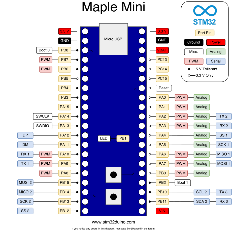
The default pin mapping with the current core for Maple Mini is above. We prefer in this forum to NOT reference pins … they have mixed meaning, so talk about ports, PA2 and PA3 would be port A,2 (Tx2) and port A,3 (Rx2) … these are the signals specified on the uC itself.
This .h file explains how the UARTS are mapped to resource pins:
https://github.com/rogerclarkmelbourne/ … reSerial.h
In summary:
#define DEFINE_HWSERIAL(name, n)                                   \

HardwareSerial name(USART##n,                                  \

BOARD_USART##n##_TX_PIN,                   \

BOARD_USART##n##_RX_PIN)
#define DEFINE_HWSERIAL_UART(name, n) \
HardwareSerial name(UART##n, \
BOARD_USART##n##_TX_PIN, \
BOARD_USART##n##_RX_PIN)
/* Roger clark. Changed class inheritance from Print to Stream.
* Also added new functions for peek() and availableForWrite()
* Note. AvailableForWrite is only a stub function in the cpp
*/
class HardwareSerial : public Stream {
public:
HardwareSerial(struct usart_dev *usart_device,
uint8 tx_pin,
uint8 rx_pin);
/* Set up/tear down */
void begin(uint32 baud);
void begin(uint32 baud,uint8_t config);
void end();
My Question should be: is it eas possible to change the mapping ?
– via the boatloader
– via a headerfile
Result: No ! (i believe)
Fazit: I have not 10.000 PCBs, i have may only 5 left, so i change it via Hardware an fix the next version…
Thanks for the Infos.
See
http://www.st.com/content/ccc/resource/ … 161566.pdf
See page 32
You either need to use different pins or use the afio_remap function
I recall someone posted how to remap those pins
[RogerClark – Sat Feb 10, 2018 10:08 am] –
…
I recall someone posted how to remap those pins
Aargh! ![]()
- In one case, the procedure failed
- In another case, the remapping worked but 3rd party libraries failed with initialization issues
Remapping of internal fabric comes with many caveats, too many to support IMO as a forum solution.
The hardware being used is not like the PSoC where pin remapping is a graphical drag&drop operation.
Even with PSoC, some pins refuse to remap.
So, I cannot recommend remapping as a solution within the confines of this Forum. There is simply not sufficient time to work with the user’s sketch, the libraries, and a frustrated user in hopes that voodoo mapping will solve an issue.
Ray
I agree it’s far easier just to connect it to the correct pins
Or…
There is another active thread about Software Serial, which they could read.
But it could still be a lot more problematic than simply using the correct pins

