EDIT: I finally solved this, please see http://www.stm32duino.com/viewtopic.php … 8474#p8474 for more info
I’m at the end of my wits ![]() I have read the ADC and DMA docs at least 5 times each. Looked at the RegSimul_DualMode example from ST (and that was fun enough, since it uses completely different conventions than the Arduino/Maple libraries but in the end I understand what it does)… and I still can’t make it work… help, please.
I have read the ADC and DMA docs at least 5 times each. Looked at the RegSimul_DualMode example from ST (and that was fun enough, since it uses completely different conventions than the Arduino/Maple libraries but in the end I understand what it does)… and I still can’t make it work… help, please.
Problem statement: on a Maple Mini, using STM32duino, convert 4 analog channels (connected to pins D3-D6, i.e. IN8-5, respectively) and transfer the data in memory using DMA (I need fast and predictable timing).
I basically would need to combine “dual simultaneous mode” with “continuous scan”, in order to capture ~2000 samples from each channel. But I fear it might not be possible, and the only mention I found is here (no reply, though) https://my.st.com/public/STe2ecommuniti … x?tags=adc
The code below sets a sequence for each ADC: in SQR1 sequence length is 1 (i.e. 2 conversions), and I set the SQR2 registers to have ADC1 convert IN8 while ADC2 converts IN7, then ADC1 convert IN6 while ADC2 converts IN5. I set regular (not injected) SW triggers.
After setting the ADC1 and ADC2 registers and the DMA1 Channel 1, in theory setting ADC1->regs->CR2 |= ADC_CR2_SWSTART; should start the conversion for the master ADC1 and slave ADC2 and in parallel start the DMA (one 32 bit DMA transfer for each conversion: in dual mode the ADC1 SR register holds both the values for ADC1 and ADC2).
What I noticed, though, is that when ADC_CR2_CONT is enabled, the ADC continuously scans, and the DMA keeps sending data to my buffer. What that means is the the order of the odd and even channels in the buffer can be off. Basically, when ADC_CR2_CONT is enabled, the ADC keeps scanning all the time, and that triggers DMA transfers in a random order.
If I don’t use ADC_CR2_CONT, I can only sequence a limited number of channels (and even if I repeat the sequence, I can only still do 16 conversions per ADC max (using SQR1-3). Or I can convert 2 channels (one on ADC1, one on ADC2) continuously in parallel…
But there seems no way to do scan and dual simultaneous at the same time… am I missing something? Any suggestion? If this doesn’t work, I can use two Maple Mini synchronized to capture 4 channels, but it makes everything harder to code (one as a master, one as a slave, with the conversion triggered at the same time, and transferring data)
Here’s my non-working code (if you uncomment the delay() statement you will see the problem)
EDIT: removed non-working code, see http://www.stm32duino.com/viewtopic.php?f=3&t=757&p=8474#p8474 for working code
However I would not mention you are using the Arduino IDE etc, as I get the impression they only like people using their CMSIS / HAL
But you could post the question with the same technical detail as above and see if they can tell you if the hardware is capable of doing this.
The other option is to use external switching or external ADCs, or both, i.e use one very fast external ADC and an analog multiplexer or mulichannel input
e. mcp3208
( IF and its a big IF something like to mcp3208 can be preprogrammed to cycle through 4 inputs and just have data pulled via SPI DMA )
<…>
( IF and its a big IF something like to mcp3208 can be preprogrammed to cycle through 4 inputs and just have data pulled via SPI DMA )
Good point.
The PSOC is almost certainly a better device for this application
(PS. Still not got around to using mine even though as I have 3 of them I could unbrick them if I stuffed up by not including the bootloader module ![]()
I also just saw that the F303 actually has 4 ADCs (and they can be programmed to be 12/10/8/6 bits). I’m still getting up to speed on the STM32 family, does anyone have a good F303 board to suggest? Would this be a good starting point? http://www.newark.com/stmicroelectronic … scovery+F3
I’d love if something like this actually were manufactured: http://sustburbia.blogspot.co.uk/2014/0 … 3-arm.html. I know I could build my own using this http://ebrombaugh.studionebula.com/embe … index.html, but building such a small pitch SMD board is not that simple
Any other “cheap” F303 boards that work with STM32duino? (I’m assuming that the eval kit above does work)
Thanks for the PSOC suggestion, I’ll look into it. My only concern is that’s yet another platform to learn, while with the F303 I can keep leveraging the same set of skills, and there are a lot of STM32 boards getting cheaper and cheaper and easier to find. I’m assuming that the PSOC won’t work anytime soon with STM32duino…
All I did was adopt someone else’s F3 version of LibMaple, however I’ve not had time to try it at all, and its not been maintained or updated like the F103 stuff has been
If the F4 series has the same capabilities as the F303 then I’d recommend you look at the F4 instead.
We have reasonable support for the F4 (but not as good as the F103)
You can get reasonably priced F407 boards like this one http://www.aliexpress.com/item/5pcs-lot … eb201560_7
And I think you can get even smaller and cheaper ones (I’m sure someone posted a link a while ago, but I can’t remember what it was with reference to)
BTW. Those little F303 boards look nice, but I’ve found that soldering the MCU’s is difficult even on the F103 (I’ve ruined several boards trying)
Unfortunately I can’t find an F4 chip that has 4 ADCs… 3 is as high as I can find (which is not to say it doesn’t exist, just that I can’t find it ![]() )
)
EDIT: I just discovered that the F3 family is designed with signal processing in mind, that’s why it has much faster ADC, more channels, more configurability, better DAC, etc… F4 tends to be rather lacking in the ADC compartment
Given what you say about F3 and F4 support, i think I’ll either look into the PSOC or go to my backup plan (use 2 F103 as master slave).I might still get an F303 just to play with it, next time I need something from Mouser or Newark, $10.88 aren’t much money (the main downside of that board is that a lot of pins seem to be connected to on board peripheral, like accelerometers, etc)
<…>
My only concern is that’s yet another platform to learn, while with the F303 I can keep leveraging the same set of skills, and there are a lot of STM32 boards getting cheaper and cheaper and easier to find. I’m assuming that the PSOC won’t work anytime soon with STM32duino…
PSoC is GNU and the free compiler default usage is bundled with a GNU distribution. You can also purchase Keil, a limitrd eval version is downloadable for free.
PSoC is unlike any uC you have used, unless you are into Verilog. The default drag-n-drop designer software has a VHDL back-end to configure switched network fabric snd pins I/O… just about any package pin can be assigned independently. The uC is ARM M0+ running at 48MHz.
The PSoC will never be an Arduino board under the ArduinoIDE. The PS0C 4200 prototype board is $4. The $20’ish 4200 Pionerr board has builtin hardware debug to the C-source code, with variables view, breakpoints, etc.
Ah, I am old and retired, I live to learn YAP (yet another platform.)
Ray
But the Cypress PSoC 4200 is 48Mhz instead of the 72Mhz on the STM32
Actually if you want to stay with something like the STM32 but its not quite fast enough, the GD32 boards are faster and the same price.
GD32 are specced to run at 108Mhz and have zero wait state flash memory which makes them faster even at 72Mhz
96Mhz is the fastest you can run the GD32 and still have USB and be within their spec, however if its just for a hobby type thing, then I’m running my GD32’s at 120Mhz , which is another multiple that supports USB, and it works fine under normal room termperature operation.
I actually measured the temperature with an IR thermometer and the chips do get a few deg hotter when tunning at 120Mhz compared with 72Mhz but really nothing that would concern me.
And if it really was an issue, you could always stick on one of those little heat sinks that they use for the stepper driver chips on the reprap 3d printer RAMPS board.
With the F103, I might also find a way to use the parallel mode and some fast code to fill a buffer (need to mull this over for a bit)… With a F303, I can do 4 conversions at once, not requiring interpolation.
BTW.
I know you are not using SPI, but FYI
With the current SPI DMA code, it’s “blocking” and does not return until the transfer is complete, however we could add some new variants of the dmaTransfer() function, one of which could have a completion callback.
Even our current “blocking” DMA SPI is much faster than getting the ARM processor to push data to the SPI subsystem
We have established that the signal is in the audio domain, so <20kHz, the STM32F103 ADC is capable of 2Mhz fast interleaved mode, as demonstrated on the Pig-O-Scope (so about 100 times faster than would be needed for audio).
What sample rate do we require to give us our time delay?
What is the distance between the mics, and what resolution do we require from our signal (i.e. how accurate does our result need to be).
Which STM32 ADC conversion mode is most appropriate for our application, I would suggest Dual regular simultaneous mode, but I’m open to other suggestions.
does it have to be dual? simultaneous?
how fast could it do sequential conversions of the 4 channels, adc1, adc2, adc3, adc4 ? (and dma them?)
what would the resulting phasing difference in the readings cause in terms of the calculations (distances)?
what are you expecting distance accuracy to be?
what’s 4m/5m at speed of sound? mS uS nS
really big wall:-)
stephen
does it have to be dual? simultaneous?
It turns out that using both continuous conversion and DMA creates a few tricky timing conditions that have to be met. It doesn’t matter when used like in the O-Scope, since you are scanning only one channel per ADC. When scanning more than one channel per ADC, timing matters a lot.
The moment you enable the ADC in continuous mode (any dual mode), the ADC keeps running, and writing the converted value for ADC1 and ADC2 in the DR register of ADC1. At the end of each conversion, it sets the EOC bit in register SR, and that in turns tells the DMA to read the content of register ADC1->regs->DR and transfer it to memory. In the case of the O-Scope, the ADC is always running and sampling, and when DMA is enabled in the takeSamples() function, it starts transferring right away. Since DR always contains the same 2 channels (one for ADC1, one for AC2), it works.
When you have a sequence of channels to be sampled, if you use the same approach, the DMA transfer starts as soon as you enable the DMA. Problem is, the ADC is always running, and you don’t know what channels are in the DR register at that time. If like me you have 4 channels (IN8 and IN6 on ADC1, IN7 and IN5 on ADC2), you can start the memory transfer either when IN8 and IN7 are there, or when IN6 and IN5 are there. That’s what was happening to me.
The trick is to make sure that the ADC is not running, enable DMA, then start the ADC only when needed. The DMA transfer will wait patiently until the ADC starts, then upon the first EOC will start transferring from the right set of channels (IN8 and IN7 in my case).
It turns out, though, it’s tricky to set the ADC in continuous mode and ensure that the ADC is not running (probably due to the Maple libraries already having enabled the ADC).
Doing something like:
ADC1->regs->CR2 = ( ADC_CR2_ADON | ADC_CR2_CONT | ADC_CR2_DMA | ADC_CR2_EXTSEL | ADC_CR2_EXTTRIG);
Turns out to be a bad idea, while
ADC1->regs->CR2 = ( ADC_CR2_CONT | ADC_CR2_DMA | ADC_CR2_EXTSEL | ADC_CR2_EXTTRIG);
ADC1->regs->CR2 |= ADC_CR2_ADON;
Works fine. There’s a cryptic note in the reference manual, 11.12.3. It says “If any other bit in this register apart from ADON is changed at the same time, then conversion is not triggered. This is to prevent triggering an erroneous conversion”. Well, it turns out that changing a bunch of bits together while changing ADC_CR2_ADON doesn’t stop a conversion either (and this was a real puzzler for the longest time). When I enabled ADC_CR2_CONT, the ADC was already enabled and even if the ADC_CR2_SWSTART bit was not set, started running. When later on I thought I was starting conversion using ADC_CR2_SWSTART, made no difference (since it was already running), and that’s why the DMA transfer started happening randomly (seemingly randomly, I can now say).
So the trick is to set the CR2 register while explicitly disabling the ADC. That stops everything. Then enable just ADC_CR2_CONT. At this point the ADC is “armed” and waiting for ADC_CR2_SWSTART to actually start the continuous conversion.
So, assuming the ADC1 and ADC2 registers are set in your init code, the right order to start a new conversion is:
- Disable the ADC, and set the CR2 register as needed
Enable the ADC
Set the DMA
(do whatever you need to do to decide when the conversion is ready to start, trigger or otherwise)
Set ADC_CR2_SWSTART to finally get the conversion going
In my case it’s critical to start converting all 4 channels as close as possible to the trigger, because in order to cross correlate various sound waves, the initial slope is pretty critical (and likely the strongest part of the sound impulse for impulsive sounds). It might be critical for an oscilloscope in order to capture a single high speed signal (but, then again, you can run quite a few ARM instructions in a CPU running at 72MHz, maybe I worry too much)
Here’s the working code:
/* MapleDualADC - A sample to perform dual ADC conversions using DMA */

//

// As written it performs a total of NUM_SAMPLES dual conversions (ADC1 and ADC2) on Maple Mini

// continuosly scanning the defined channels (D3->IN8 and D5->IN7 in the first conversion

// followed by D4->IN6 and D6->IN5 on the second conversion). In the example, repeated 4 times

// NUM_SAMPLES=(number INx channels converted/2) * number of times each channel is scanned

/*

Copyright (c) 2015 Roberto Cazzaro.  All rights reserved.
This library is free software; you can redistribute it and/or
modify it under the terms of the GNU Lesser General Public
License as published by the Free Software Foundation; either
version 2.1 of the License, or (at your option) any later version.
*/
#include <libmaple/dma.h>
#define CHANNELS_PER_ADC 2 // number of channels for each ADC. Must match values in ADCx_Sequence array below
#define NUM_SAMPLES 8 // number of samples for each ADCx. Each channel will be sampled NUM_SAMPLES/CHANNELS_PER_ADC
#define SAMPLE_RATE ADC_SMPR_71_5 // when using dual mode, each pair of channels must have same rate. Here all channels have the same
uint32 adcbuf[NUM_SAMPLES+1]; // buffer to hold samples, ADC1 16bit, ADC2 16 bit
uint8 ADC1_Sequence[]={8,6,0,0,0,0}; // ADC1 channels sequence, left to right. Unused values must be 0. Note that these are ADC channels, not pins
uint8 ADC2_Sequence[]={7,5,0,0,0,0}; // ADC2 channels sequence, left to right. Unused values must be 0
// calculate values for SQR3. Function could be extended to also work for SQR2 and SQR1. As is, you can sequence only 6 sequences per ADC
uint32 calc_adc_SQR3(uint8 adc_sequence[6]){
int SQR3=0;
for (int i=0;i<6;i++) // There are 6 available sequences in SQR3 (SQR2 also 6, and 4 in SQR1).
{
//each sequence is 5 bits
SQR3 |= adc_sequence[i] << ((i*5));
}
return SQR3;
}
// initialize DMA1, Channel1 (ADC)
void set_dma() {
dma_init(DMA1);
dma_setup_transfer(DMA1, DMA_CH1, &ADC1->regs->DR, DMA_SIZE_32BITS,
adcbuf, DMA_SIZE_32BITS, DMA_MINC_MODE);
dma_set_num_transfers(DMA1, DMA_CH1,NUM_SAMPLES);
dma_set_priority(DMA1, DMA_CH1, DMA_PRIORITY_VERY_HIGH);
dma_enable(DMA1, DMA_CH1);
}
// calibrate ADC1 and ADC2, then set all registers for regular simultaneous dual ADC conversion with DMA transfer
void set_adc() {
adc_set_sample_rate(ADC1, SAMPLE_RATE); // sets sample rate for all channels, all identical (critical in dual mode, even if only pairs sampled together need to be identical)
adc_set_sample_rate(ADC2, SAMPLE_RATE);
adc_calibrate(ADC1);
adc_calibrate(ADC2);
ADC1->regs->CR1 = 1 << 8; // Set scan mode
ADC1->regs->CR1 |= 6 << 16; //Regular simultaneous mode. Required for ADC1 only, ADC2 is slave
ADC1->regs->CR2 = ( ADC_CR2_CONT | ADC_CR2_DMA | ADC_CR2_EXTSEL | ADC_CR2_EXTTRIG); //0xe0102; cont conversion, DMA, right aligned, disable external; EXTSEL, exttrig=0,jswstart=0
adc_set_reg_seqlen(ADC1, CHANNELS_PER_ADC); // how many channels per ADC
//ADCx->regs->SQR3-1 holds the sequence of channels to convert. A conversion function is provided calc_adc_sequence(ADC1_Sequence) only for SQR3.
//If more than 6 channels are needed, repeat the same for SQR2 and SQR1 (SQR1 only holds 4 sequences)
ADC1->regs->SQR3 |= calc_adc_SQR3(ADC1_Sequence); //200; for IN8 and IN6, on Maple Mini these are D3, D5
ADC2->regs->CR1 = 1 << 8; // Set scan mode
ADC2->regs->CR2 = ( ADC_CR2_CONT | ADC_CR2_EXTSEL | ADC_CR2_EXTTRIG); //0xe0003;
adc_set_reg_seqlen(ADC2, CHANNELS_PER_ADC);
ADC2->regs->SQR3 |= calc_adc_SQR3(ADC2_Sequence); //= 167 forIN7 and IN5, on Maple Mini these are D4, D6 respectively
ADC1->regs->CR2 |= ADC_CR2_ADON; // it is critical to enable ADC (bit 0=1) independently of all other changes to the CR2 register
ADC2->regs->CR2 |= ADC_CR2_ADON; // enabling all at once (i.e. ADC_CR2_ADON | ADC_CR2_CONT | ADC_CR2_EXTSEL ) will cause problems when used with continuous mode
}
// set only the registers that need to be reset before each conversion
void adc_to_ready() {
ADC1->regs->CR2 = ( ADC_CR2_CONT | ADC_CR2_DMA | ADC_CR2_EXTSEL | ADC_CR2_EXTTRIG); //0xe0102; cont conversion, DMA, right aligned, disable external; EXTSEL, exttrig=0,jswstart=0
ADC2->regs->CR2 = ( ADC_CR2_CONT | ADC_CR2_EXTSEL | ADC_CR2_EXTTRIG); //0xe0002;
ADC1->regs->CR2 |= ADC_CR2_ADON; // it is critical to enable ADC (bit 0=1) independently of all other changes to the CR2 register
ADC2->regs->CR2 |= ADC_CR2_ADON; // enabling all at once (i.e. ADC_CR2_ADON | ADC_CR2_CONT | ADC_CR2_EXTSEL ) will cause problems when used with continuous mode
}
// check for DMA transfer finished, resetting isr bit
uint8 dma_transfer_finished() {
if(dma_get_isr_bits(DMA1,DMA_CH1)==0x07) {
int result=dma_get_irq_cause(DMA1,DMA_CH1);//<--clears isr bits
return 1;
}
return 0;
}
void setup() {
Serial.begin(115200); // Ignored by Maple. But needed by boards using Hardware serial via a USB to Serial Adaptor
pinMode(3,INPUT_ANALOG); //set all used pins as INPUT_ANALOG, in the example 3,4,5,6
pinMode(4,INPUT_ANALOG);
pinMode(5,INPUT_ANALOG);
pinMode(6,INPUT_ANALOG);
set_adc(); // initial ADCa and ADC2 settings
}
void loop() {
adc_to_ready(); // it is critical to set ADC before DMA, to avoid partial DMA transfers being stored. If the ADC is in continuous mode while DMA is being set
set_dma(); // the DMA transfer will be triggered and the DMA counter will start from the wrong value
ADC1->regs->CR2 |= ADC_CR2_SWSTART; //start conversion, STM32 will reset this bit immediately. Only ADC1 (master) needs to be started
while(!dma_transfer_finished());
dma_disable(DMA1,DMA_CH1); //stop dma transfer
for(int i=0;i<(NUM_SAMPLES);i++) {
Serial.print(i);
Serial.print(" ");
Serial.print(adcbuf[i] & 0xFFFF);
Serial.print(" - ");
Serial.println((adcbuf[i] & 0xFFFF0000) >>16);
}
Serial.println();
delay(750);
}
If a few other eyes could check my figures, and assuming they stack up, we can then see how to try to implement this.
#include <libmaple/dma.h>
in my code to ensure that I can properly access the DMA registers, but I do not need the equivalent for the ADC? Did I setup my Arduino environment wrong? I used the installation steps you list here https://github.com/rogerclarkmelbourne/ … stallation
Not a real issue, just curious to understand better how the STM32duino libraries work
Libmaple is the core, not a library.
We never changed the name that was inherited from the code written by Leaflabs for their Maple and Maple mini products.
you would need to include dma.h if you want to use any of the built in dma functions, but it sounds like what you need to accomplish would require various settings of the dma registers which are more complex than the basic stuff in the core dma code
My question still stands, though: if I want to use direct registry access for the DMA, I need to add libmaple\dma.h. I’m using direct DMA registry access (because as you say it’s the only way to really manipulate the registers: built-in functions are good for standard stuff, but once you understand how the DMA/ADC works, direct registry access is faster and more flexible). So I use things like DMA1->regs->CCR1
But I also use things like ADC1->regs->CR2, and that works without any include… I guess I’m just curious to understand why ADC1 and ADC1 work, while DMA1 requires an include. Honestly, not that important, just curious ![]()
.../Arduino_STM32$ grep -r include |grep adc.h |grep f1
STM32F1/system/libmaple/include/libmaple/adc.h:#include "stm32f1/include/series/adc.h"

STM32F1/system/libmaple/stm32f1/include/series/adc.h: * included in all copies or substantial portions of the Software.

STM32F1/system/libmaple/stm32f1/include/series/adc.h: * @file libmaple/stm32f1/include/series/adc.h

STM32F1/system/libmaple/stm32f1/include/series/adc.h:#include <libmaple/bitband.h>

STM32F1/system/libmaple/stm32f1/include/series/adc.h:#include <libmaple/libmaple_types.h>

STM32F1/system/libmaple/stm32f1/include/series/adc.h:#include <libmaple/rcc.h>       /* For the prescalers */

STM32F1/cores/maple/stm32f1/util_hooks.c:#include <libmaple/adc.h>

STM32F1/cores/maple/libmaple/adc_f1.c:#include <libmaple/adc.h>
The question (please look at Andy’s post before yours) is why adc.h is auto-included, but dma.h is not. Is it a configuration problem?
I mean, can be easily addressed, I just wonder if it’s something worth addressing
The trigger code works, and it’s followed by a very fast sampling loop perfectly capable of capturing the types of wave form I need for the TDOA analysis. I can see plots of my samples with GNUplot ![]()
I’m running into a problem, though, and I think it has to do with how the ADC and mic amplifiers interact. I hope someone here might be able to shed some light.
To get started, I have these cheap modules http://www.ebay.com/itm/3-3V-3-5V-MAX98 … 1742472725, and they use a MAX9812 amplifier https://datasheets.maximintegrated.com/ … X9813L.pdf. The circuit is pretty much the reference circuit (plus a XC6206 LDO to power the MAX9812 with 3.3V). Please note that the MAX9812 is a fixed gain amplifier, which is what I want to avoid problems with AGC
According to the datasheet, the output impedance is 0.5 Ohm, and that should work well for the F103 ADC.
But I’m seeing a very weird behavior with that amplifier (but not with just an electret microphone): the average sampled value is around 2000 (out of 4096, makes sense). But when I have a trigger, you can see the initial sample to be much lower (around 1250), and then it drifts back to 2000. Please see the attached image.
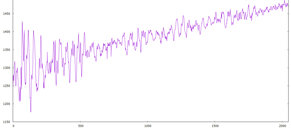
- ADCdrift.PNG (42.53 KiB) Viewed 682 times
long time back, i had to write automated test equipment software for a 16 input analogue multiplexor.
unused channels were supposed to be in mV, but not 300mV; that’s about 5% of the input test signal.
turned out the input filtering capacitors were acting as a potential divider.
stephen
Ah.
I see what you mean.
Can you try editing the file that includes adc.h and add an include for dma.h and let me know if it causes any build problems.
If it works, let me know and I will update the core
…
When I want to also test (but haven’t had time to get the soldering iron) is what happens if I bypass (short circuit) the capacitor on the out.
Do you have any other suggestion on how to address the weird drift I’m seeing?
Its either there to provide isolation or to remove a DC offset, but you may be better off with a resistor divider network if the issue is the supply voltage on the MAX9812 (assuming its not 3.3V)
From memory I thought the input impedance of the STM32 was somewhere in the range of 50k. Well I recall a tech note that said that care should be taken when trying to read external inputs with impedance of greater than 50k. Which probably means the input impedance is more than 50k but not in the meg ohm range.
BTW.
I think for this sort of work having a scope is almost essential.
<…>
BTW.
I think for this sort of work having a scope is almost essential.
I occasionally look to upgrade, but I can think of better things to spend $2k on ![]()
I’m also in this trouble, my analog scope is pretty old, more than 25 years old, and limited to 10MHz.
For tear down and repair pictures, follow the link.
https://plus.google.com/u/0/photos/1110 … 2229320338
Its a Metrix OX-803B 40MHz – so a good old fashioned analog scope. In addition I of course have the Pig-O-scope, but it is very limited in its abilities, and another HP 100MHz analog that is 99% functional, and awaiting further “medical intervention”, when I have some spare time.
Next to a couple of multimeters I think a good oscilloscope probably one of the most important tools to have.
I occasionally look to upgrade, but I can think of better things to spend $2k on ![]()
that’s teasing; mention p&p
i’ve never understood fft, what would it give me in this situation?
stephen
I occasionally look to upgrade, but I can think of better things to spend $2k on ![]()
I would love to have one of those Rigol scopes.
I was about to write that I don’t use 75% of the features…
So I fired it up and pressed the MATH button, and … It does do FFT !!
![]()
![]()
![]()
i’ve never understood fft, what would it give me in this situation?
stephen
I tried shorting the capacitor: the mic amplifier is powered from the 3.3V supply of the Maple Mini and there’s an LDO with a ~250mV drop (which I will remove, since it’s not needed and needlessly reduces the range), so it’s safe to bypass it. Predictably the voltages are a bit lower: the resistor network I used before forced the capacitor to “float” at exactly half of VCC (~1.65V), while the output of the amplifier when there’s no signal is half of the amplifier voltage, i.e. ~1.5V. In either case conversion is stable and noise acceptable. So I have a decent starting point to make progress coding, and can finalize the hw design later on.
Good point about creating a RC filter with the addition of the resistor network, I will have to figure out what values work better. I also found this http://electronics.stackexchange.com/qu … as-of-2-5v and there’s a mention to use 100k resistors for a similar case (in that case they use 5V, but nothing would change with 3.3V). But 100K might be too high for the F103, which wants to see a low impedance on its input.
Please keep the suggestions/ideas coming ![]()
i’ve never understood fft, what would it give me in this situation?
stephen
I was about to write that I don’t use 75% of the features…
So I fired it up and pressed the MATH button, and … It does do FFT !!
![]()
![]()
![]()
Ah.
I see what you mean.
Can you try editing the file that includes adc.h and add an include for dma.h and let me know if it causes any build problems.
If it works, let me know and I will update the core
never practised as a mech eng
i was tempted to reply to someone with ‘as in a sonar waterfall display’
clue was in the ’60Hz signal and propeller blade 25Hz’ comment
the cat has just sat on my laptop table, its heaving down outside and she wants to go outside!
i thought she was going to crouch covering the mouse.
stephen
I ran some tests, and the critical place where adc.h is defined but dma.h is not is STM32F1\cores\maple\wirish_types.h (thanks to Andy for suggesting how to look into this).
I ran some tests, and the critical place where adc.h is defined but dma.h is not is STM32F1\cores\maple\wirish_types.h (thanks to Andy for suggesting how to look into this).
- 4 channel sampling works reliably at every sampling speed
- I managed to write reasonably fast trigger code for 4 channels triggering, and quick sampling of all 4 channels after sampling
- As expected, RAM is very tight. So instead of implementing a faster FFT-based cross correlation algorithm, I’m using a simple general cross correlation algorithm. Basically loops and multiplications, requiring no extra array. I can cross correlate 4 channels of 2048 samples in ~3 seconds. Slow, but not a killer for me. The FFT-based algorithms (like GCC PHAT) would operate much faster and provide better correlation in the presence of noise or with low volume signals, but would require 4x the memory or so. Even on processors with more RAM, I would need to store things temporarily in flash (or SD card). Since it would be nice to store all samples on SD card (for post-processing with better tools), adding an SD card is my next step
Which brings me to my next question. Is https://github.com/victorpv/SdFat the best SD card library for STM32duino? I looked at a few older posts, and there were a lot about non-working libraries, but no real “definitive” answer on a working one. It would be nice if an “official” SD card library could be added to the existing ones
Less relevant question: clearly the cheap eBay amplified microphones have serious limitations for sound capture (but are great for cheap prototyping). Does anyone know of a microphone/preamplifier that could be used for this project? I know that there are plenty of high quality microphones, but they all cost well above $50, which is well above the price point for this experiment. I will try replacing the crappy electret capsule on those with a decent one (like http://www.jlielectronics.com/products/JLI%252d61A.html, a clone of the well known Panasonic WM-61A, now obsolete), since the amplifier used by the cheap eBay modules is actually pretty good
Less relevant question: clearly the cheap eBay amplified microphones have serious limitations for sound capture (but are great for cheap prototyping). Does anyone know of a microphone/preamplifier that could be used for this project? I know that there are plenty of high quality microphones, but they all cost well above $50, which is well above the price point for this experiment. I will try replacing the crappy electret capsule on those with a decent one (like http://www.jlielectronics.com/products/JLI%252d61A.html, a clone of the well known Panasonic WM-61A, now obsolete), since the amplifier used by the cheap eBay modules is actually pretty good
I mostly need a capsule with low noise. As long as all the capsules pick up the same frequencies, my code works. I’m trying to build a pretty generic location engine, but most sounds that work well tend to be impulsive in nature: gunshots, clapping, knocks, etc. I trigger based on level, not frequency (would be impossible to do it quickly enough and still capture the samples). I keep sampling 4 channels for one cycle, and whatever channel gets above or below the trigger levels, it starts the 4CH conversion with 2048 samples per channel.
EDIT: the eBay capsules are the same as used on the modules. Cheap, low quality Chinese junk. Replacing them would make no difference. I’m sure that there are high quality Chinese capsules, but we won’t find them on eBay
Then I cross correlate, and spit out the samples and the correlation values (which sample is the most likely to start the same waveform as the trigger channel). Right now I simply plot them with GNUplot:
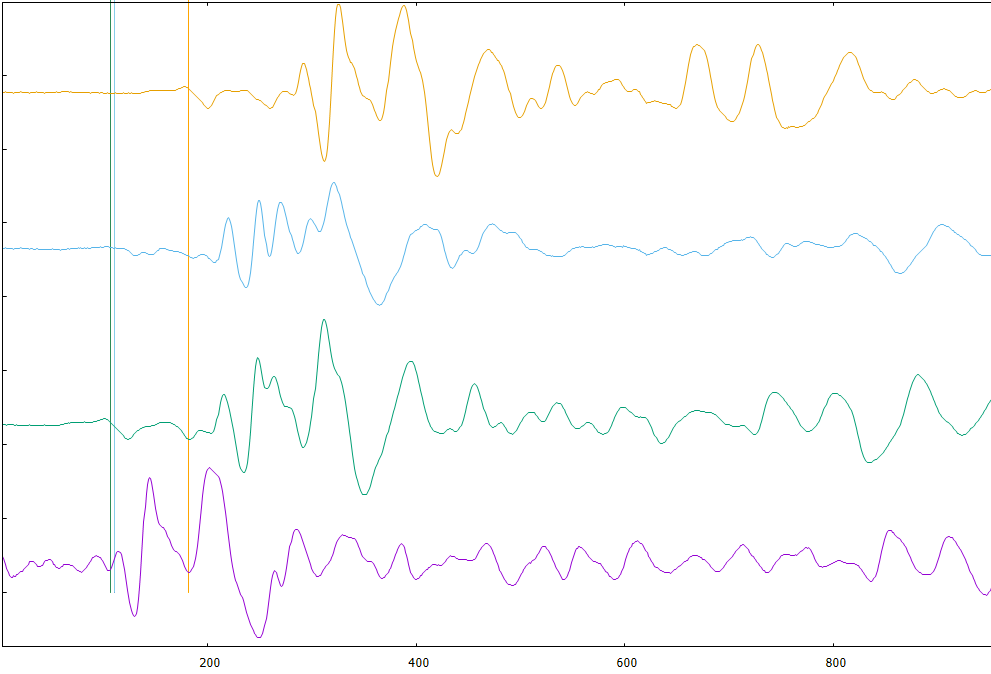
- adc4ch.PNG (38.86 KiB) Viewed 779 times
There is a thread about this a while ago, by @stevestrong
He got SD working much better
So search for his postings
Also, you should update to use the development branch of the repo as it has steve’s SD fixes
Cheers
Roger
If I download https://github.com/rogerclarkmelbourne/ … master.zip I see that the files are from Nov 21. Is there a newer development branch? The thread you referred me to was around the end of October, so the Nov 21 files should be updated, right?
EDIT: I also just noticed the below in this page https://github.com/rogerclarkmelbourne/ … /Libraries
Latest SdFat, modified version from https://github.com/victorpv/SdFat seems to work fine. If you want the best performance for large transfers, can use DMA mode, but that requires the latest SPI Library from https://github.com/victorpv/Arduino_STM … raries/SPI . Does not need the updated SPI files if you don’t use DMA mode. DMA can be enabled or disabled editing SdSpiSTM32F1.cpp, read the file to know what to modify.
Is that info still correct? If not, might be worth updating the page
I mostly need a capsule with low noise. As long as all the capsules pick up the same frequencies, my code works. I’m trying to build a pretty generic location engine, but most sounds that work well tend to be impulsive in nature: gunshots, clapping, knocks, etc. I trigger based on level, not frequency (would be impossible to do it quickly enough and still capture the samples). I keep sampling 4 channels for one cycle, and whatever channel gets above or below the trigger levels, it starts the 4CH conversion with 2048 samples per channel.
EDIT: the eBay capsules are the same as used on the modules. Cheap, low quality Chinese junk. Replacing them would make no difference. I’m sure that there are high quality Chinese capsules, but we won’t find them on eBay
Then I cross correlate, and spit out the samples and the correlation values (which sample is the most likely to start the same waveform as the trigger channel). Right now I simply plot them with GNUplot:
adc4ch.PNG
<edit> for a testing data set, </edit>
don’t you just need a single recorded input, the other 3 signals can be generated from the separation distances
for the ‘mics’, maybe chuck in a rand call as noise.
i did something similar with a user specified function in a kernel device driver at work, level sensors show variation when taxi’ing.
stephen
Thanks for your help
sorry for posting so late, but I just read this post and though I share some information with you.
We (my friend and I) are also working on something similar, up to 8 channels are converted quasi instantaneously (via sample-and-hold) in regular intervals given by a timer and stored on SD card in contiguous 512 byte blocks, several seconds long sampling.
The storing speed is mostly limited by the card write latency, we are using class 10 cards, capable of up to 80mbps, but still is very limiting.
Thus, the higher the channel number, the less the sampling frequency for the same amount of data.
Alternatively, in order to be able to store more data, we thought to implement a kind of delta compression: for a 512 byte block only store the first samples for each channel in full 12 bit resolution, for the following samples only the delta to the previous sample should be stored. Dependent on the sampling frequency, these deltas can be stored in 8 or 4 bit wide fields, saving ~ 55% or 70% of data storage space.
Problem: there is very high noise on the analog inputs when data is being stored on the card! We couldn’t get rid of it, no matter how intensively filtered, the noise (+-40lsb !!!) is still there. Also tried to make differential value from the useful samples, no solution, because it turned out that the noise is not always evenly distributed.
That’s why our next idea is to separate sampling and SD storage in time, to use one STM32 only as converter which is sending the acquired data (after sampling) via SPI to the second STM32 responsible to store/process the data. And this is the point where I am blocked currently, the slave SPI doesn’t want to work.
Any thoughts/comments on this?
For your interest, here is our project:
https://github.com/stevstrong/Audio-sample
My repos also contain the current SDfat and STM32 versions I am using.
There is also a folder named “tools”, I coded a web-based signal monitor GUI, and processing based application for data dumping over UART with up to 500kBauds.
Steve
Ground couldn’t separate, on these cheap boards is not possible.
I saw on the original Leaflabs maple mini there are separated grounds and Vcc for analog and digital parts, very probably not without any reason.
The Baite clones and all other chinese boards have one common power supply for analog and digital, so it seems hopeless.
That’s why we tried the separated boards, which seems to confirm our strategy.
Meanwhile, the slave SPI started to work.
I have an iTead Studio Maple, which appears to be well made.
https://www.itead.cc/iteadmaple.html
They seem to have taken designed the board well, but I’m not sure about the separate analogue grounds. You could take a look at the schematic and confirm if it looks any better than the Baite Maple Mini
Schematic: ftp://imall.iteadstudio.com/IM120411012 … dmaple.pdf
At $5.80 its competatively priced. Its just a shame they use the STM32F103RBT not the STM32F103RET, ad the RET has DAC etc, at marginally extra cost.
This would be optimal:
https://github.com/leaflabs/maplemini/b … lemini.pdf
Separated grounds (by ferrite) and second A-Vdd.
Its a shame they didnt do that, as they seem to have gone to a lot of trouble elsewhere on the board e.g. with the power supply being far more complicated than on the Maple mini etc
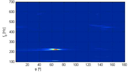
in case of periodic signal detection, it is possible to derive a 2D representation,
where one dimension is frequency(pitch), the other one is DoA(direction of arrival),
and colours(intensity) represent the probability that a source is present at given Freq and DoA.
this 2D position-pitch plane is extremely robust against non-periodic noise.
more details here:
https://signalprocessingideas.wordpress … opi-plane/
in case you are interested, i got it implemented in octave.
mrn.
But would that work with a single percussive sound (like a shot)? there’s really no frequency to speak of, in those cases
I fully implemented a sound location algorithm, btw. Works pretty well: 4 microphones, uses hyperbolic location (heavily modified version of the multilateration algorithm defined in IT++: https://sourceforge.net/projects/itpp/). The slowest part is cross correlating the sample (I’m using a general cross correlation algorithm, optimized for my sampling strategy) . Depending on the precision I want to achieve, I can get a location in anywhere between 1 and 3 seconds after the sound capture.
I could maybe speed up cross correlation using FFTs, but the devices I’m using simply do not have enough memory to do so. And even using a device with more memory might not improve cross correlation enough to justify the effort: an F1 using integer math is not that fast calculating FFTs
Unfortunately “life happened” before I completed the project and cleaned it up for publishing… Hope to publish it soon, though
I checked the recording you posted few months ago, it seems to be really non-periodic
Unfortunately, the method would give you almost the same result as the cross-correlation based estimation.
There would be one single vertical line present in the decomposition, meaning, the estimation would be spread over the whole frequency range.
Regarding the speed of the cross-correlation: once you know roughly the DoA of the source, you can reduce the calculation of the cross-correlation to only those time-lag candidates (DoA-candidates), which are close to the source position from the previous estimation.
Example: there is a strong peak at 50 Degrees indicating a source, then from the next frame onward, it is enough to compute the cross-correlation for those values,, which are close to 50 Degrees (let say to scan from 30 degs to 60 degs) instead of scanning the whole (0-180)Degs space for a given mic pair. in case of moving sources, of course, it is necessary to update those values.
good luck!
M.
Since there was no code or example at the link you provided, it’s really hard to say how long (and how much memory) would it require… If you have more info, I’d be interested
basic code above.
will create a github page with the lokup-tables (150kB text file), audio samples, etc.
Do you really use the xcorr() function in your algorithm? If so, well, that’s the only slow part in my code ![]() . I had to implement a fast version of xcorr for my data sets, and I managed to reduce the time to calculate cross correlation to ~15% of the more generic algorithm for the same data set (accepting some limitations that, in my case, are not significant)
. I had to implement a fast version of xcorr for my data sets, and I managed to reduce the time to calculate cross correlation to ~15% of the more generic algorithm for the same data set (accepting some limitations that, in my case, are not significant)
Outside of xcorr, my algorithm is running in only a few msec, and doesn’t use any additional memory. Just to give a sense, of the less than 20Kb Ram available, I’m using 16Kb for the samples data, so only a couple of Kb are left for additional variables. There’s no room for a lookup table or much else
If we had plenty of memory, it would be easier to implement a FFT based cross correlation, using integer-based FFT with lookup tables. But there’s simply no room for any lookup table in an F103 (yes, I could use a device with more memory, which is what I plan to do in the future)
Anyway: the weak part of my code is having to implement xcorr() in an efficient way
Here is the github link, there should be all files you will need to run the demo-decomposition.
There is the main routine, “popi_demo”, written and tested in octave.
Then the audio samples, the lookup tables, in txt format, and there is even an xcorr function i used, from Paul Kienzle.
https://github.com/m-r-n/popi-toolbox
I would be interested in the cross-correlation algorithm you used, as I will need soon one when rewriting this decomposition for an embedded platform.
Regards, mrn.
In any case, that code doesn’t help me any ![]() it’s for a periodic frequency, and designed to help locate a speaker in a room (2D space), using 2 microphones. My code works on percussive sounds, with a 4 microphone array, in full 3D, and depending on the microphone array size, can work from anything from a few cm to many km (assuming a sound loud enough to be heard clearly above the noise threshold). We are interested in completely different problems
it’s for a periodic frequency, and designed to help locate a speaker in a room (2D space), using 2 microphones. My code works on percussive sounds, with a 4 microphone array, in full 3D, and depending on the microphone array size, can work from anything from a few cm to many km (assuming a sound loud enough to be heard clearly above the noise threshold). We are interested in completely different problems
Here’s my code. I store all my samples as 16 bit integers in an “interleaved array” (i.e. sample1_ch1, sample1_ch2, sample1_ch3, sample1_ch4, sample2_ch1, sample2_ch2, sample2_ch3, sample2_ch4, etc). So I need to traverse my array in increments of 4.
The gcc() function is a modified general cross correlation. Out of my 4 samples, one is identified as the “trigger channel” (the first microphone that receives a signal), and I always cross correlate the trigger channel with the 3 other samples. By doing so, I can cut the correlation scan to half the space (because I will never be in a case where the trigger channel will have a negative correlation value). I also only scan 1/3rd of the signal, because my trigger signal is percussive, and only the first 1/3rd of the sample contains significant information for the cross correlation.
Not sure how relevant this optimization would be in your case… otherwise you’ll have to use the general cross correlation algorithm (here’s is a version, but it’s really a pretty wasteful version http://www.jot.fm/issues/issue_2010_03/column2/)
#define SAMPLES_CH 2048           //ADC Samples per channel (each 16 bit)

#define SAMPLES_BUF SAMPLES_CH*4  //Total size of 16 bit buffer

#define SAMPLES_32 SAMPLES_CH*2   //ADC buffer (2 CH per conversion)
int32_t adcbuf32[SAMPLES_32+1]; // buffer to hold samples, ADC1 16bit, ADC2 16 bit
int16_t *adcbuf16 = (int16_t *)&adcbuf32; //same buffer, but as 16 bits
int16_t gcc(int16_t *trigger, int16_t *array2)
{
int32_t dotprod = 0;
int32_t maxv = 0;
int pos = 0;
for (int j = 0; j < SAMPLES_BUF; j+=4) // creates a sliding window (positive only, since first array is always trigger). Array is made of four 16 bits elements, need to move in 4 increments
{
dotprod = 0;
for (int i = 0; i < MIN(SAMPLES_BUF/3, SAMPLES_BUF-j); i+=4) // no need to check all samples for trigger microphone, roughly first 1/3th should be enough; stop when i+j=SAMPLES_BUF
{
dotprod += trigger[i] * array2[i+j]; //weighting function. If more than 2048 samples per channel, might overflow
}
if (dotprod > maxv)
{
maxv = dotprod;
pos = j/4;
}
}
return pos;
}
thanks for hint (storing lookup tables), the details and the code!
– regarding the differences between the two methods:
although the pitch-dependent DoA estimation code uses only 2 mic signals, by triangulating two pairs of microphones you can get to similar representation, as with the TDOA method. The pitch is just one extra dimension, (just like a parameter,) and yes, it is redundant (useless) in case of your problem. Reason: for percussive sounds there would be no significant point in the decomposition indicating a single frequency at a single tdoa (or doa) value, but a vertical line, spreading over the whole frequency range. Of course, at the correct doa (tdoa) value.
– regarding the octave code: there are three steps:
– pairwise cross-correlation of mic-signal frames (result: vector sl),
– dot product calculation between the cross-correlation vector (sl) and the 3 lookup-tables (popiLUT_L, popiLUT_0, popiLUT_R), result : 3 matrices
– and finally summing the three dot-product-matrices, result: one single matrix (cut1) with the same resolution.
Note: there is a png image demonstrating this in the repository.
– regarding the lookup tables:
the idea to store them with the executable sounds great, however, I also have no idea how fast is it to calculate dot-products of vectors stored in the RAM and matrices stored in the flash. have to try ![]()
– the lookup tables can be re-calculated for any mic-distance (cm to meters, as you say) and to any pitch range (just in case one day you decide to analyze periodic signals).
cheers!
– regarding the lookup tables:
the idea to store them with the executable sounds great, however, I also have no idea how fast is it to calculate dot-products of vectors stored in the RAM and matrices stored in the flash. have to try
– the lookup tables can be re-calculated for any mic-distance (cm to meters, as you say) and to any pitch range (just in case one day you decide to analyze periodic signals).
cheers!
– and finally summing the three dot-product-matrices, result: one single matrix (cut1) with the same resolution.
I’ve been trying with simult 2 ADCs but 1 channel per each ADC (so 2 values per sample).
I’ve done following changes:
#define CHANNELS_PER_ADC 1   // number of channels for each ADC. Must match values in ADCx_Sequence array below

#define NUM_SAMPLES 8192        // number of samples for each ADCx. Each channel will be sampled NUM_SAMPLES/CHANNELS_PER_ADC

#define SAMPLE_RATE ADC_SMPR_71_5  // when using dual mode, each pair of channels must have same rate. Here all channels have the same
uint32 adcbuf[NUM_SAMPLES+1];  // buffer to hold samples, ADC1 16bit, ADC2 16 bit

uint8 ADC1_Sequence[]={8,0,0,0,0,0};   // ADC1 channels sequence, left to right. Unused values must be 0. Note that these are ADC channels, not pins

uint8 ADC2_Sequence[]={7,0,0,0,0,0};   // ADC2 channels sequence, left to right. Unused values must be 0
https://github.com/stevstrong/Audio-sam … _Slave.ino
[zmemw16 – Thu Jul 13, 2017 7:31 pm] –
with apologies to agatha c, but why didn’t they ask @ahull
Don’t ask him, he knows nothing ![]()
