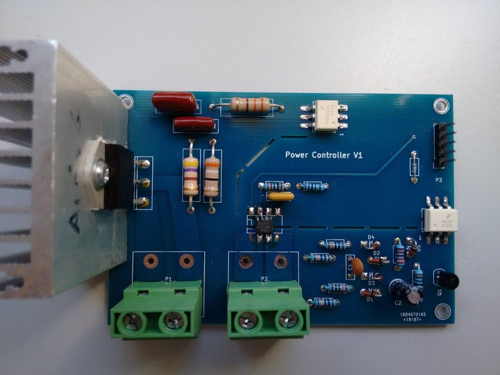
There is a dimer working on the scheme http://www.instructables.com/id/Arduino … e-circuit/
The resistor ratings are replaced, the circuit is working.
The question is this. Is it possible to replace the zero detector with a timer?
volatile uint16 i = 0;

volatile boolean zero_cross = 0;

uint16 dimming = 128;
void zero_cross_detect() {
zero_cross = true;
i = 0;
gpio_write_bit(GPIOA, 1, 0);// turn off TRIAC (and AC)
}
void handler_AC() {
if (zero_cross == true)
{
if (i >= dimming) {
gpio_write_bit(GPIOA, 1, 1);
i = 0;
zero_cross = false;
}
else {
i++;
}
}
void setup()
{
//afio_cfg_debug_ports(AFIO_DEBUG_SW_ONLY);
pinMode(PA1, OUTPUT);// Set AC Load pin as output
attachInterrupt(PB0, zero_cross_detect, CHANGE);
Timer2.pause();
Timer2.setChannel1Mode(TIMER_OUTPUTCOMPARE);
Timer2.setPeriod(75);
Timer2.setCompare1(1);
Timer2.attachCompare1Interrupt(handler_AC);
Timer2.refresh();
Timer2.resume();
}
void loop() {
dimming = 95;
}
I’m not very strong in the timers, so I thought maybe I did not start it correctly.
You cannot estimate it, as the mains frequency is not 100% accurate (and neither is the timer on the STM32F103), so there will always be some discrepancy between the two. So the electricity utility companies idea of what 50Hz or 60Hz is, will differ by a certain un-knowable percentage from the STM32F103’s idea of what 50hz or 60Hz is, furthermore both of these values will drift over time, due to other factors, such as temperature, accuracy of crystals, speed of turbines in the power plant and so forth..
There is no escaping the need for some form of zero crossing point detector for this kind of dimmer i’m afraid. ![]()
There are a few GotYa’s with this stuff
Firstly the basic zero crossing detector you are using,is very susceptible to mains noise, and its likely you will get a trigger when your fridge turns on or any fluorescent lights are turned on or off.
Also, the zero crossing is triggered long before the actual zero crossing. I can’t remember exactly when its triggered but it could be 10 degrees before zero etc.
Also… The circuit is really wasteful, as it uses high wattage resistors to drop the mains voltage to the 2 or 3 v needed to light the LED in the opto coupler. Half watt resistors will get hot as they will need to dissipate around 0.96W i.e 96% of their maximum rated value
I tried this circuit and found problematic and now use a more complicated circuit, which uses a transistor as well as an opto. But at the moment I can’t find the circuit I used.
In your sketch, you need to start the timer when the zero crossing occurs, and turn on the triac when the timer interrupt is called.
Because your Zero crossing detector will trigger long before the real zero crossing, you will be able to get away with turning off the triac in the zero crossing detector, but if you use a better zero crossing detector, which detects the crossing more accurately, then there can be problems with the triac not turning off in time, before it gets latched on in the next half cycle.
So I ended up just turning the triac on for a short period (in the timer ISR) in theory triacs need a reasonable long ON time, but in practice it didnt need to be that long at all
You will find with your zero crossing detector that you can’t operate in the range below about 5% of phase angle and above 90 to 95%, and most firmware’s cheat and below 5 they turn off all the time and above 90% they turn the triac on all the time.
This may be OK for you, but is noticeable on some loads.
One final thing, which it took me ages to resolve, is that if you switch on at 50% though the cycle, you get 50% power but if you turn on at 25% phase angle you do not get 25% power (in watts).
This is because of the nature of the sine wave. i.e very little power is in the area (V * I) in the first 25% of the cycle.
The only way to resolve this is to use a lookup table – and it took me ages to build my lookup table as the maths is not solvable by normal methods.
It has to be solved by Newton Raphson approximation.
However the electricity companies have to keep it pretty accurate as its uses for time keeping, so I didnt both with that
But small jumps are tolerable, it’s not for lamps, it’s for a heating element that does not create light but only heat.
what you are are using is fine for a heater.
BTW. I found the circuit I used

http://dextrel.net/diyzerocrosser.htm
I built a 5kW heater controller, custom PCB, But in the end I never used it.
4N35 – PC814
5.1k – 4.7K on 3.3v
On this code, a couple of controllers operate, from 0.5 kw to 4 kW.
There were no problems.
And in general to what I raised this issue.
The controller came in and changed the temperature sensor.
Works on pic16f690, ac dimmer, but it uses moc3023 and BTA16,
and there is no Zero Cross Detector.
So it became interesting how can it be on the timers it works
[RogerClark – Mon Dec 11, 2017 10:46 am] –
…
Also… The circuit is really wasteful, as it uses high wattage resistors to drop the mains voltage to the 2 or 3 v needed to light the LED in the opto coupler. Half watt resistors will get hot as they will need to dissipate around 0.96W i.e 96% of their maximum rated value
…
It occurs to me, you might get better efficiency from a capacitive dropper. https://en.wikipedia.org/wiki/Capacitive_power_supply
The opto provides isolation, so the schematic from pokemon has isolation.
About using it without cross detection, you could modulate power by turning on for a number of cycles, then off for a number of cycles, rather than for a percentage of each cycle.
In that way you may turn on in the middle of a cycle, which is not ideal, but then you stay for for say the period of 200 cycles, and then off for 55 (if you use 8bits of resolution).
You could then set the timer to match your mains frequency (50 or 60 hz), but you will not be in sync. I think that would cause more interference to other systems.
So tnank you. The problem itself was not, the circuit works.
I wanted to know if there was an opportunity, run on two timers, that’s all.
[pokemon99 – Mon Dec 11, 2017 5:19 pm] –
I wanted to know if there was an opportunity, run on two timers, that’s all.
You can, the switching won’t be synchronized with the AC wave, so no good for lighting, but for a heater you should be ok.
I do something similar for my reflow oven controller, and works fine, though I plan to enable zerocross detection now that I have a custom board for it.
This is my project, I used to be without a web interface, now I’m expanding the functionality when there is time
http://62.80.175.55:85/
login:admin
pass:22222
but It depends on the purpose of the system.
I built a system to use surplus solar electricity, and it was very important that the system did not use more power in each cycle ( actually each half cycle) than was available in the surplus
So tuning in a 4kW heater for 1 second and then off for 9 seconds to give 10% power usage was no good, because for those 9 seconds all the surplus power goes to waste, and in the first 1 second, the system needs to get 3.6kW from the grid.
Andy: I saw and example circuit that used a capacitor instead of resistors , but I am not sure how well it works.
There is even an Atmel application note where they connect the MCU GPIO directly to the mains via a very high value resistor.
I.e. It is possible to power the MCU via one of those capacitive power supplies , so that the whole circuit is not isolated from the mains, and you don’t need an opto at all, as you can drive the gate of the triad directly from the MCU ( assuming the MCU can deliver enough current from its GPIO, e.g. via paralleling a whole port of pins together and turning them all on or off at the same time using the BSSR reg)
And if control is via radio, the whole thing can be safely put in an isolated box.
However… it’s very hard to debug problems in this scenario, and if you get things wrong the MCU goes up in smoke very quickly
So it’s not an approach I have taken. But it is the approach used by those radio controlled inline mains sockets
I also met the circuit where a diode bridge and a mosfet are used, but I have never tried it
I guess you could have an insulated “handle”
Sounds possible, but I would not build something that was unisolated for a personal project.
[Pito – Mon Dec 11, 2017 5:15 pm] –
Afaik the MOC304(6,8)x devices include the zero switching detector, so you must not mess with a special circuit..
I can’t find a MOC3046 or MOC3048 listed on mouser or Digikey
Are you sure those are the correct part numbers
Edit. There is an opto with 2 back to back LEDs inside which will conduct in either direction, which removes the need for the external bridge rectifier, but it has the same issues with high wattage resistors, and is a lot more expensive than using a single LED opto and a cheap bridge ( or 4 diodes)
The bridge does not need to be high voltage as the resistors drop all the voltage.
BTW.
probably using 4 resistors is better than 2, because most resistors that are readily available do not guarantee to 240V RMS, peak is 350V and spikes can be even higher.
So using 4 resistors gives a better operating margin.
Also be aware that you should not use normal strip-board to build the zero crossing detector, as it may “track”across the insulation
Or if you do, then feed the mains to it via the resistors, so the voltage drop is done before it gets to the board
Pito may have misstyped 6/8
@Pokemon:
This is my zero crossging ISR:
https://github.com/victorpv/reflowOvenC … w.ino#L155
But as you see here, I am simulating it with a timer to use it without zero cross detection:
https://github.com/victorpv/reflowOvenC … #L223-L228
The code is a fork from someone else, I only wrote the part where I fake the zerocrossing.
You could use a second timer, or do like I did and call it from the ISR for another timer every N cycles.
I use an SSR with zero cross detection for the highest load (15 amps) and a triac with no zero cross detection for the smallest (a fan).
As for the heater switchint on an off for long periods is ok (my range is 0 to 100, so slightly shorter than 120 ac half cycles I get in the US with 60 hz main, so the switching period is a bit under 1 second, and duty from 0 to 100%), and the fan is either full on or full off, works fine for me.
Obviously this would not work for lighting, because it would flicker, since the on/off wouldn’t be fully synchronized with the AC waves (on top on mine period is almost 1 second…)
I looked at the data sheet for the moc3043 but the Zero crossing part if the chip something to do with only turning on the triac at zero crossing and not part of the detection as far as I can see
I think it’s for a different use, where you have a highly inductive load and don’t want to turn on half way though a cycle ( but I could be wrong)
[RogerClark – Mon Dec 11, 2017 8:49 pm] –
VictorI looked at the data sheet for the moc3043 but the Zero crossing part if the chip something to do with only turning on the triac at zero crossing and not part of the detection as far as I can see
I think it’s for a different use, where you have a highly inductive load and don’t want to turn on half way though a cycle ( but I could be wrong)
That’s right Roger, it’s not for the MCU to detect zero cross, but to ensure the load doesn’t turn on mid cycle.
So it’s helpful if you want regulate the load to be on for a number of cycles, then off for a number of cycles, like with a heater.
It doesn’t help with loads like a light bulb in which you want to regulate by using a turning on during part of each cycle to avoid flicker.
I was just pointing out that the MOC3043 is one that Pito was referring to with integrated zero cross.
- IMG_20171212_153930.jpg (86.63 KiB) Viewed 1719 times
Of course not as beautiful as you have Roger, but I have enough
BTW. I found it was cheapest to buy a high power dimmer board from eBay, then remove the triac and heat sink.
The only problem is that the position of the screws for the heat sink can change, if you order some more dimmers, even if you order from the same vendor.
Yes, himself. But it’s made for cnc machine.
[RogerClark – Tue Dec 12, 2017 10:50 pm] –
Do you mean its “routed” or engraved ?
engraving and drilling
I tried that but I did not get good results. However I think it would be OK for a board like that which does not have very small SMD components
[RogerClark – Wed Dec 13, 2017 8:35 am] –
OK.I tried that but I did not get good results. However I think it would be OK for a board like that which does not have very small SMD components
smd size 1206, good
Far easier to just get the boards made in china
At the moment AllPCB seem to be doing amazing deals, but all the others are cheap as long as you are willing to wait for slow deliver
I’ve only used DirtyPCB’s and they were OK, and relatively cheap
PS. Can you take a photo of the bottom / copper side of your PCB.
Its important that you mill large gaps between the live and neutral lines. I think ideally this distance is quite large
I think were possible I tried to have 2.5mm separation (no copper at all)
See
http://www.smps.us/pcbtracespacing.html
Also as I had a 2 layer PCB made, I’m using both sides of the board to carry the power
The main problem keeping 2.5mm separation, is that its not possible at triac its self, because the pins are only about 3 or 4mm apart.
I presume ideally the tracks need to be tapered as they approach the triac, but that’s tricky on KiCad unless perhaps the track is a zone.
My pulse widths are 1.25mS rather than 1mS (500us before and after the crossing)
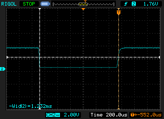
- zero_crossing.png (6.28 KiB) Viewed 477 times
const int  ZERO_CROSSING_PIN =14;

const int  TRIC_TRIGGER_PIN =13;
volatile boolean zeroCrossingState = 0;
uint16_t dimming = 500;
char buf[16];
char *bPos;
void zero_cross_detect()
{
zeroCrossingState = digitalRead(ZERO_CROSSING_PIN);
if (zeroCrossingState==0)
{
// end of half cycle
Timer2.pause();// cant trigger the tric now, its too late !
Timer2.setCount(0);// get ready to start again
Timer2.setOverflow(dimming);
Timer2.refresh();
digitalWrite(TRIC_TRIGGER_PIN,LOW);
}
else
{
// beginning of half cycle
Timer2.resume();
}
}
void triggerDelayHandler()
{
// Can't turn the triac while the zero crossing input is low
Timer2.pause();
if (zeroCrossingState)
{
digitalWrite(TRIC_TRIGGER_PIN,HIGH);// Turn on the triac
}
}
void setup()
{
dimming = 750;// global volatile
pinMode(TRIC_TRIGGER_PIN, OUTPUT);// Set AC Load pin as output
pinMode(ZERO_CROSSING_PIN,INPUT);
digitalWrite(TRIC_TRIGGER_PIN,LOW);// Turn on the triac
attachInterrupt(ZERO_CROSSING_PIN, zero_cross_detect, CHANGE);
Timer2.pause();
Timer2.setChannel1Mode(TIMER_OUTPUTCOMPARE);
Timer2.setPrescaleFactor(720);
Timer2.setOverflow(dimming);
Timer3.setCount(0);
Timer2.attachCompare1Interrupt(triggerDelayHandler);
}
void loop()
{
if (Serial.available())
{
bPos=buf;
while(Serial.available())
{
*bPos++ = Serial.read();
}
*bPos++='\0';
dimming=atoi(buf);
}
}
I susoect what may be happening, is that the Timer is not being paused in the ISR, before the next interrupt arrives.
I know there is higher latency on some interrupts than others as they have shared vectors, but I will need to check if Timer2 shares its vector.
The prescaler is set to 720, so that each count is 100,000 clock cycles, so I am surprised that setting an overflow of 1 , means that the ISR does not get serviced in time to pause the Timer
Perhaps a value of 1 causes an immediately trigger of ISR?
14.3.15 One-pulse mode
Starting the counter can be controlled through the slave mode controller. Generating thewaveform can be done in output compare mode or PWM mode. Select One-pulse mode by
setting the OPM bit in the TIMx_CR1 register. This makes the counter stop automatically at
the next update event UEV.
A pulse can be correctly generated only if the compare value is different from the counter
initial value. Before starting (when the timer is waiting for the trigger), the configuration must
be:
• In upcounting: CNT < CCRx ≤ ARR (in particular, 0 < CCRx)
• In downcounting: CNT > CCRx
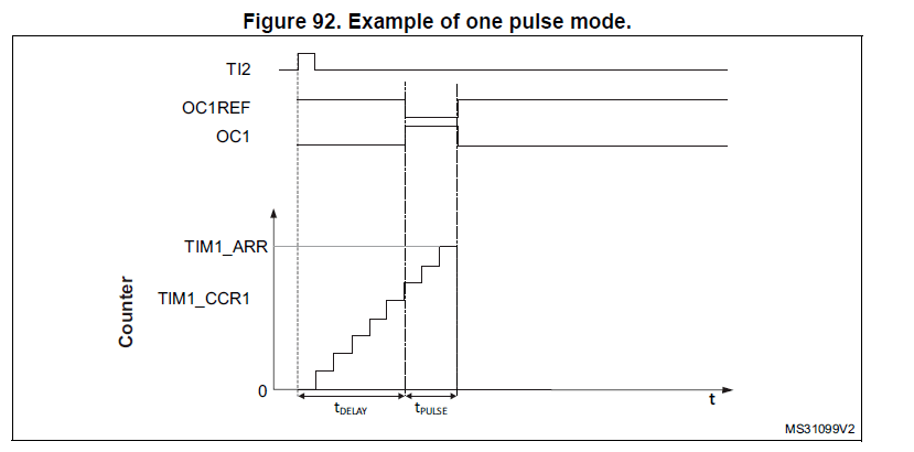
- stm32_one_pulse_mode.png (16.57 KiB) Viewed 446 times
1) I think a 32-bit chip for this is an overkill. an 8-bit chip can do it without breaking a sweat.
2) if you are looking for a speedy execution, I would suggest that your initialize the peripherals outside of the isr. this generally can be done with two isrs (a exti + timer), but sometimes one isr (timer) will work as well – if you load up the timer isr with an -1 offset, it becomes an exti isr.
3) you can greatly simplify the zero cross circuitry, especially if you assume the positive half and the negative half are symmetrical.
4) ST has an appnote for this utilizing STM8. using the input thresholds of a digital pin to detect zero crossing. I can provide a link if you are interested.
6) for those extremely adventurous, you can switch an AC load with a bridge + mosfet. the lowest cost solution.
I agree that a 32 bit MCU is overkill for just operating the dimmer.
However, I didn’t outline the whole system. It’s part of a control system, for electrical loads, ( mainly water heating, but also oil filled radiators, and other electrical heaters where the deman can be modulated)
The purpose of the system is to use spare solar electrical generation capacity , rather than the power being sent to the grid; as the Feed In Tariff for solar is either zero ( in this particular case) or a small percentage of the buy back price ( in most cases)
Hence it pays to find some way to use the solar electricity yourself.
Heating water is generally more cost effective than battery storage of the power, as a lot of people already have electric water heaters.
The same STM32 that I intend to control this, is already running a disolay unit, which receives data via a 433 MHz link, ( nRF905 ) And turns the load on and off using a relay.
In the enhanced system the STM32 still has to receive the data every 500 mS and update the disolay, also I intend to use a Hall effect current sensor ACS712 to monitor the actual power taken by the load and run a control system using PID.
( I am going to use the Hal sensor, as updates every 500 mS from the master power monitor system make the PID system rather slow at controlling the dimming to achieve the optimum demand to consume all available free power as soon as possible )
Hence offloading the pulse delay and pulse width, to the Timer hardware makes sense as it will not get affected by the other things the STM32 is doing.
I did PID + pwm on a solder iron build and minimum benefits between that and the simple on/off control.
But if you just want to play with it, that’s another story.
Re: On / Off or PWM vs dimming
I think it probably depends on how the electricity company measures the power you are consuming or exporting.
I’m actually building this for a fairly small scale water heater (1kW or 2kW), though it may get used for larger things
The existing system uses a relay, but because its for use in the UK where they often get a lot of cloud cover and low angle of the sun, so solar production on a 4kW array may only be 500W. Then simply tuning on the heater when there is 1kW or 2kW available, means that the system doesnt turn on much in the winter if the sun is not that high in the sky etc etc
Conventional PWM won’t work, because the cheaply available power controllers use a triac rather than power FET.
And by the nature of sine waves, most of the power is in the middle of each half wave.
I guess using a FET with PWM much faster than mains frequency would work.
However for some reason FETs used in all the inverter I’ve played with , seem to have a nasty habit of being destroyed by spikes on the mains
And I’ve learn t by experience that the $5 600V 30A FETs on eBay are junk.
Anyway. I’ve actually got the system working now ![]()
But, here is the code I’m using to test ramping the dimmer up and down
#include <Streaming.h>

uint16_t pulseDelay = 8500;

uint16_t pulseWidth = 100;

void setup()

{

pinMode(PA1, PWM);  // setup PA1 (Timer2 channel 2) to PWM (one pulse mode)

pinMode(PA0, INPUT);  // setup PA0 (Timer 2 channel 1) as input (capture input mode)
Timer2.pause(); // stop the timers before configuring them
timer_oc_set_mode(TIMER2, 2, TIMER_OC_MODE_PWM_2, TIMER_OC_PE);
Timer2.setPrescaleFactor(72); // 1 microsecond resolution
Timer2.setOverflow(pulseWidth + pulseDelay-1);
Timer2.setCompare(TIMER_CH2, pulseDelay);
// counter setup in one pulse mode, as slave triggered by External input for Timer 2
TIMER2_BASE->CR1 = ( TIMER_CR1_OPM ); // one pulse mode
TIMER2_BASE->SMCR = ( TIMER_SMCR_TS_ETRF | TIMER_SMCR_SMS_TRIGGER );
TIMER2_BASE->CCER = ( TIMER_CCER_CC1E | TIMER_CCER_CC2E ); // enable channels 1 and 2
Timer2.refresh(); // start timer 2
Timer2.resume(); // let timer 2 run
}
void updateDelay(uint16_t dly)
{
// Timer2.pause();
Timer2.setOverflow(pulseWidth + dly-1);
Timer2.setCompare(TIMER_CH2, dly);
// Timer2.refresh(); // start timer 2
}
char buf[16];
char *bPos;
int direction=1;
int increment=20;
const int minDelay=0;
const int maxDelay=9000;
uint16_t oldPulseDelay;
void loop3()
{
Serial.println(Timer2.getCount());
}
void loop()
{
if (direction==1)
{
if (pulseDelay<maxDelay)
{
pulseDelay+=increment;
}
else
{
direction=0;
pulseDelay-=increment;
}
}
else
{
if (pulseDelay>minDelay)
{
pulseDelay-=increment;
}
else
{
direction=1;
pulseDelay+=increment;
}
}
while(Timer2.getCount() !=0);
updateDelay(pulseDelay);
delay(50);
if (Serial.available())
{
bPos=buf;
while(Serial.available())
{
*bPos++ = Serial.read();
}
*bPos++='\0';
updateDelay(atoi(buf));
}
}
uint32_t t;
void loop2()
{
if ( (millis()-t)>1000 )
{
t = millis();
Serial << millis()
<< ", TIM2->CCMR1: " << _HEX(TIMER2_BASE->CCMR1)
<< ", TIM2->CCER: " << _HEX(TIMER2_BASE->CCER)
<< ", TIM2->SMCR: " << _HEX(TIMER2_BASE->SMCR)
<< ", TIM3->CCMR1: " << _HEX(TIMER3_BASE->CCMR1)
<< ", TIM3->CCER: " << _HEX(TIMER3_BASE->CCER)
<< ", TIM3->SMCR: " << _HEX(TIMER3_BASE->SMCR) << endl;
}
}
Another question — don’t you get an analog reading from the Hall effect current sensor? Could you use that to detect zero crossing?
[Jimmus – Thu Feb 22, 2018 9:04 pm] –
Roger, your project interests me. My brother has a solar powered water pump system, and often the pump can handle more water than the well can supply. He and I have put it on a timed system, which is working for now, but we would like to detect when it starts pumping air, or even better, when it gets close to that point. But that’s a different story — we would like to be able to use the extra power that is generated. How do you detect that you are generating more power than you are using, and how do you suck off the surplus while still supplying full power to your load? I mean in a general sense. Is it before your inverter, or after? Do you divert the top of each sine wave to your heater, or the tail end of each wave?Another question — don’t you get an analog reading from the Hall effect current sensor? Could you use that to detect zero crossing?
I built a power monitor using the OpenEnergy Monitor Arduino library
It uses a current clamp around the Live cable into the house, and it also needs a 6V mains transformer, so it can sense the mains voltage and more importantly the phase of the mains waveform.
The principal is that the OpenEnergy Monitor library uses 2 ADC inputs to sample the waveform from the current clamp and from the mains transformer
Both inputs are scaled to 3.3V i.e with 1.65V offset so that there are no negative voltages.
The library tells you voltage and current and power.
But whats more important, it tells you Power Factor
Normally when power is being consumed the Power Factor is positive and when power is being exported the Power Factor is negative
(These may be transposed, but normally you can tell by the Power Factor which way the power is going)
Its then easy to take these values and use the AC dimmer to consume power if required.
When I have simulated input solar power of 250W, and it regulates the power to a 2kW load (an electric kettle in this case), around +/-2W
I’ll need to check my measurement accuracy, as its definitely no better than +/- 1W and is possibly only +/- 2W, which would mean that the control and load control system is not adding any additional noise or inaccuracy.
I’m using a 1000 point LUT to between the output from the PID controller and the zero-crossing to delayed trigger pulse system, as the proportion of total load power to delay time, is very non linear at either end of the sine wave half cycle.
And to improve this a bit I’m interpolating between points in the LUT, as 1000 points only gives me 1/10th the resolution of my delay timer.
I experimented with removing the LUT, but I found that the PID is slow to respond to changes at the ends of the power proportions, as much much larger changes are needed and the ends.
For the PID I’m not actually using the P or the D coefficients of the PID controller, I’m only using the I (Integral) component, as the system does not gave any inertia, so the P component did not seem to be needed at all (and is set to zero)
Adding the Differential component may remove the need for the LUT, as it may speed up the response at the ends of the power range, but I’ll need to model this mathematically (probably using a spreadsheet), before experimenting with this.
I also considered changing the alternative method of pulse modulation, where the power is turned on for entire half cycles, but over a 1 second period (or 100 half cycles ), I could at best achieve 1% resolution, which for a 3kW load would be 30W, and I’d probably only be able to regulate to +/- 15 W at the very best.
I happened to some across the details of some commercial systems which do the same thing and at least one of them seems to use PWM to control the load.
Its unclear if this is being done in order to differentiate their products from competitors or for valid technical reasons.
They claim that this reduces / elimates flicker, but as these products are designed to control electric hot water heaters, I can’t see how this applies
They also claim that phase angle control causes interference, but their PWM system doesn’t. Its unclear what frequency PWM is used, possibly 100kHz.
I guess this probably depends on what the load is. But I didn’t think that electric water heaters were inductive enough to have a problem with this.
The commercial systems appear to cost around $2000, so I think I’ll stick to my system which has cost around $20 for me to build, including the Maple mini and a dimmer controller board from eBay (to source the power triac and heat sink etc) ![]()
