I’m trying to use a DS1624 with STM32Duino on a custom board that has a STM32F103T8U6.
The DS1624 is connected to the STM32 via I2C with 10K pull-up resistors.
The issue I’m having is that the temperature reading is not accurate. The sensor does respond with a temperature but the temperature is 0xFF 0X80 (255.50 C).
I’ve tried the same code on a Arduino Pro Micro (ATMEGA32U4, basically a Leonardo) and the code works there.
I think the issue is the initialization of the chip (The function InitDS1624).
When tracing the waveforms I’m seeing some differences between the STM32 and the ATMEGA.
Here is an image of the initialization sequence on the STM32 vs the ATMEGA: (FULL SIZE)
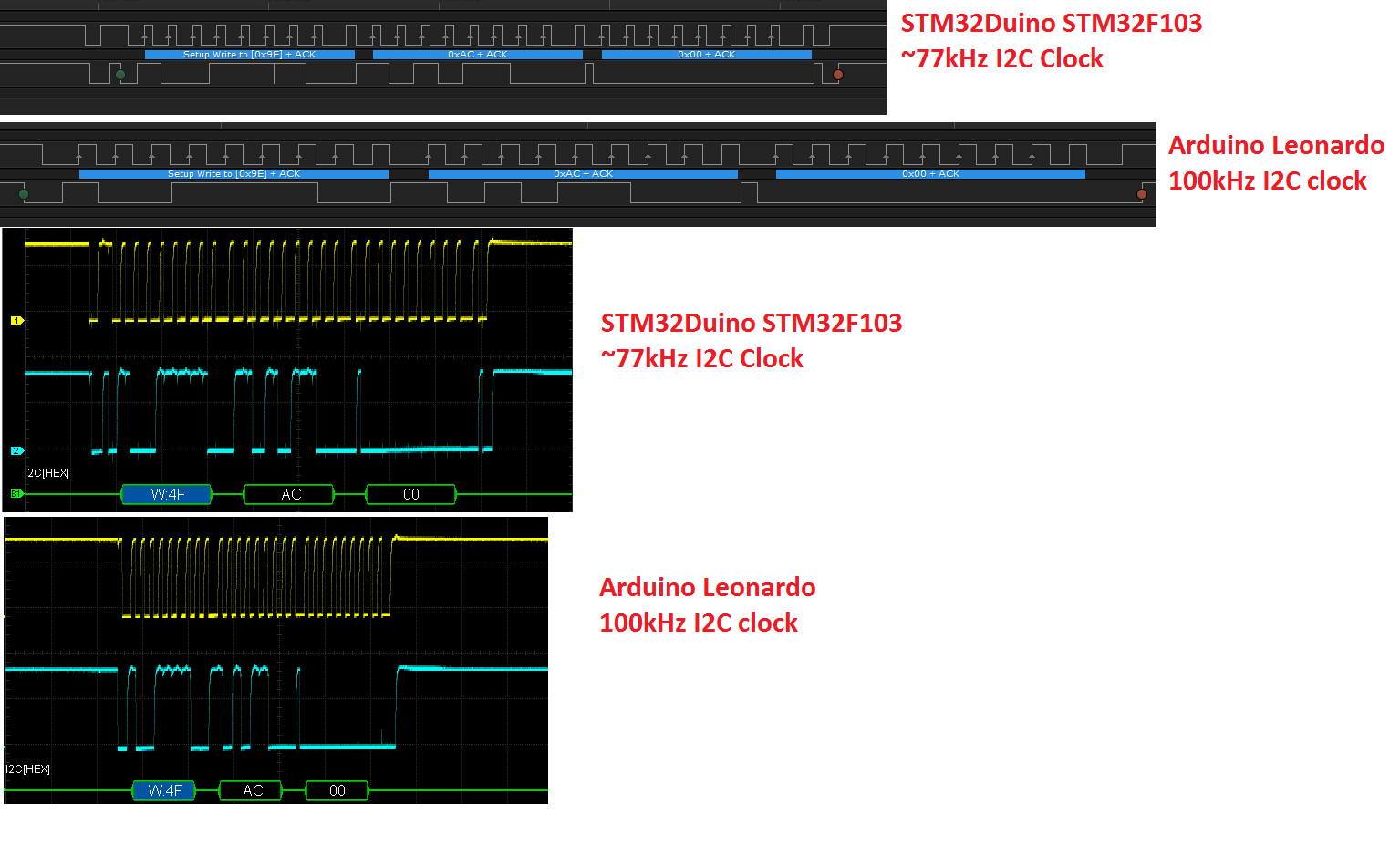
Does anyone know why the difference in the I2C waveforms and how would I be able to fix it ?
Code:
#include <HardWire.h>

#include <Arduino.h>
#define addr 0x4F
// For STM32, Serial1 is the one being used
#if !defined(__INTELLISENSE__) && defined(__STM32F1__)
#define Serial Serial1
#endif
#ifdef __STM32F1__
#define Wire HWire
#define LED PA1
#else
#define LED 15
#endif
#define CONTINUOUS_CONVERSION 0x00
#define CONVERT_T 0xEE
#define READ_T 0xAA
void InitDS1624()
{
Wire.beginTransmission(addr);
Wire.write(0xAC);
Wire.write(CONTINUOUS_CONVERSION); //Put the DS1624 in continuos conversion mode
Wire.endTransmission();
delay(100); //Min time needed to store the previous command is 10ms
Wire.beginTransmission(addr);
Wire.write(CONVERT_T); //Enable the continuos conversion mode
Wire.endTransmission();
}
float getTemp()
{
float temperature = 0;
int tempmsb = 0;
int templsb = 0;
int temp2 = 0;
Wire.beginTransmission(addr);
Wire.write(READ_T);
Wire.requestFrom(addr, 2);
if (Wire.available())
{
tempmsb = Wire.read();
}
if (Wire.available())
{
templsb = Wire.read();
}
temp2 = templsb >> 3;
temperature = (float(tempmsb) + (float(temp2) * 0.03125));
Wire.endTransmission();
return temperature;
}
void setup()
{
pinMode(LED, OUTPUT);
Wire.begin();
InitDS1624();
Serial.begin(9600);
}
void loop()
{
float temp = getTemp();
Serial.println(temp);
if (temp > 20 && temp < 50)
digitalWrite(LED, HIGH);
else
digitalWrite(LED, LOW);
delay(5);
}
This sounds too high for a 3.3V system.
Many users here (like me) used the software and the HW variant of I2C. The HW variant wasn’t really finished by leaflabs because of problems (I think a hardware bug in the STM32F1 core or something) – but:
As I told, many of us are using I2C without errors with more complex/sensitive modules, like displays.
Sadly I do not own a DS1624 so I can’t compare it with a “regular” STM32duino board like the maple mini clone. Personally, this would be my next step: Trying if the DS1624 is working with a maple mini clone (or something like that) OR trying any other I2C device on your custom board. Next problem could be the used code . It looks like it generates additional data on first and last.
Here is a generic hardwire example sketch:
http://forums.leaflabs.com/forums.leafl … l?id=74407
Maybe the old leaflabs forum could be a good point to research I2C problems.
Edit: Here are the original leaflabs docs about I2c:
http://docs.leaflabs.com/static.leaflab … i/i2c.html
Edit2:
If you repeat the I2c sequence more than 5 times: Are the spikes always on the same position?
Can’t it be the LED pin is interfering with your I2C communication?
In your sketch I can see a:
#define LED 15
Can’t it be the LED pin is interfering with your I2C communication?
In your sketch I can see a:
#define LED 15
It depends on the compilation options..
And if it’s the software i2c you’re using, then it can’t be the problem of the maple mini, since we can be pretty sure that basic port manipulation works >_<.
Using “int” as common variable (and additional bit shifting like in this code) isn’t the best way to deal with AVR and ARM code, because:
On AVR int = int16_t
on ARM int = int32_t
Maybe (or for sure) this won’t be the problem here , but I always use strictly defined variables (like int16_t) since I wrote code for both platforms.
As for the LED, that’s not the issue. I’m sure that’s the #ifdef __STM32F1__ is taken (i inserted random text inside to see if it causes errors) plus I’ve tried several variants without LED code and without serial.
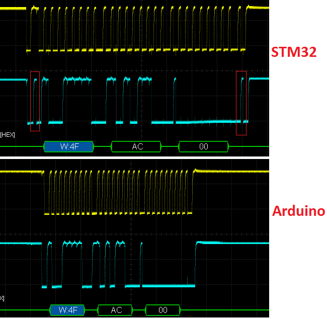
If I do a loop of InitDS1624, the spikes are in the exact same position, everything is consistent.
Notice that the first spike occurs before the I2C begin sequence.
I will also try the hardware serial with the maple mini to see if it works.
Yes, I did know about the 2/4 byte size difference and don’t think that is the issue here.
Can you post the read comparison diagrams?
Your temp reads are FF 80, correct? If yes, based on the datasheet this would mean a temp of -0.5C.
By the way, based on the datasheet it looks to me you are reading data in the wrong order, the correct order should be:
1. LSB
2. MSB
My mistake, the data order seems correct but the number is to be interpreted as a 2 complement integer so FF is -1
Best, E.
Notice the red triangles:
By the way you are using the same chip with both platforms, not 2 different chips, correct?
It was not the initialization sequence. There seems to be a bug in the wire code … perhaps ?
The following code is the one that has the issue:
	Wire.beginTransmission(0x4F);

Wire.write(0xAA);

Wire.requestFrom(0x4F, 2);

tempmsb = Wire.read();

templsb = Wire.read();

Wire.endTransmission();
The datasheet says:
   Wire.beginTransmission(0x4F);

Wire.write(0xAA);
// Wire.endTransmission(0x4F);                 // I need to add a endTransmission and an beginTransmission here

Wire.beginTransmission();                     // After this the code will work
Wire.requestFrom(0x4F, 2);

tempmsb = Wire.read();

templsb = Wire.read();

Wire.endTransmission();

