Pictures:
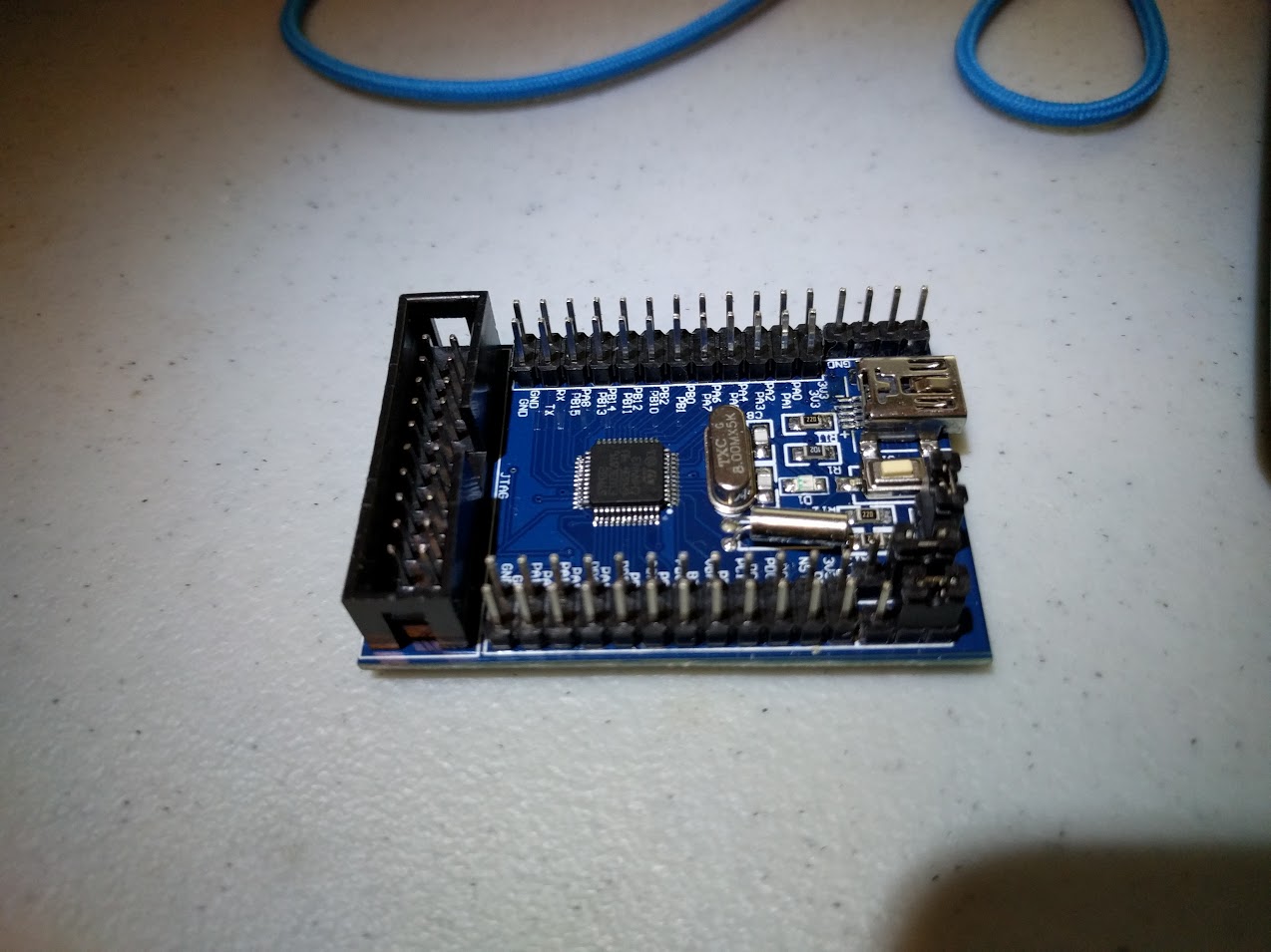
- LC-Tech-Top.jpg (140.01 KiB) Viewed 3277 times
Thanks for sharing this.
Search this forum for “ugly board”. Also be aware that as shipped there is probably a zero ohm link between VCC and VBAT called R14.
This makes life very interesting if you add a button cell to power the RTC. The battery will explode. It is in other words a bad idea, unless you have a thing for exploding button cells. See here for details.
According to the STM documentation, this link should be omitted, or should be a small value capacitor (I can’t remember which document mentions the capacitor, or its value). I removed the link, and the RTC worked fine on mine. In short, (pun intended), remove R14, it is a waste of time, and potentially dangerous.
Also check the jumper settings, I seem to recall, that they are connected in some way with the USB pins, but I can’t remember exactly how, and I don’t have the board to hand. One of them may be your mysterious short to +5V
You may find it does not boot up when not attached to a PC.
I cant get the bootloader working on that board.
I have no idea why the bootloader does not work. I thought it may be something to do with the oscillator not starting up cleanly, but I tested a few changes, but I could not get it to work.
Search this forum for “ugly board”. Also be aware that as shipped there is probably a zero ohm link between VCC and VBAT called R14.
This makes life very interesting if you add a button cell to power the RTC. The battery will explode. It is in other words a bad idea, unless you have a thing for exploding button cells. See here for details.
According to the STM documentation, this link should be omitted, or should be a small value capacitor (I can’t remember which document mentions the capacitor, or its value). I removed the link, and the RTC worked fine on mine. In short, (pun intended), remove R14, it is a waste of time, and potentially dangerous.
Also check the jumper settings, I seem to recall, that they are connected in some way with the USB pins, but I can’t remember exactly how, and I don’t have the board to hand. One of them may be your mysterious short to +5V
OK
I’m glad it works for you. But not for everyone (not me ![]() )
)
OK
I’m glad it works for you. But not for everyone (not me ![]() )
)
suspect that the poor quality control and rough soldering may be the issue with the one you have.
The average lifespan of a consumer gadget seems to vary in inverse proportion to Moore’s law (perhaps we should call that Eroom’s law, or ahulls law).
The more transistors we cram in, the shorter the lifespan of the product, so anything that extends the service life of gizmos is probably a good thing…
However having said all that, why does that idiot on the left of that big pile of crap cheap components shortly to appear in the Shenzhen electronic market (and shortly thereafter, no doubt on ebay) appear to be eating a PCB? ![]()
Slightly blurry close up after picture:

- IMG_20160305_114048-2.jpg (72.73 KiB) Viewed 1447 times
