I have spotted that my board has a 24MHz crystal and I assume the bootloader will not be configured for this. The only reference I can find in the source is in hardware.c, is this the only thing I would need to change in the code for a 24MHz crystal?
 /* Configure PLL */

#ifdef XTAL12M

SET_REG(RCC_CFGR, GET_REG(RCC_CFGR) | 0x00110400); /* pll=72Mhz(x6),APB1=36Mhz,AHB=72Mhz */

#else

SET_REG(RCC_CFGR, GET_REG(RCC_CFGR) | 0x001D0400); /* pll=72Mhz(x9),APB1=36Mhz,AHB=72Mhz */

#endif
SET_REG(RCC_CR, GET_REG(RCC_CR) | 0x01000000); /* enable the pll */
The USB needs to run at 48Mhz exactly.
So the USB can run if the PLL can produce a frequency of either 48Mhz or 72Mhz, and the divider is set respectively to 1 or 1.5.
Check the reference manual for all the details it explains clearly what’s possible and not, and how to achieve it (registers, frequencies etc)
[C_D – Mon Aug 28, 2017 9:33 pm] –
I’m trying to use the STM32DUINO bootloader on a custom board, but I cant get the bootloader to run. The micro is an F103R8T7, it has the LED on PC13 and a pull up resistor on PA12 for the USB reset.I have spotted that my board has a 24MHz crystal and I assume the bootloader will not be configured for this. The only reference I can find in the source is in config.c, is this the only thing I would need to change in the code for a 24MHz crystal?
 /* Configure PLL */

#ifdef XTAL12M

SET_REG(RCC_CFGR, GET_REG(RCC_CFGR) | 0x00110400); /* pll=72Mhz(x6),APB1=36Mhz,AHB=72Mhz */

#else

SET_REG(RCC_CFGR, GET_REG(RCC_CFGR) | 0x001D0400); /* pll=72Mhz(x9),APB1=36Mhz,AHB=72Mhz */

#endif
SET_REG(RCC_CR, GET_REG(RCC_CR) | 0x01000000); /* enable the pll */
The USB clock is derived from the main clock, so would not need to be changed if you fixed the main clock pll and set that to 24 x 3 = 72
Ps.
If you look at the settings for the GD32 board, it has a 12Mhz crystal, so you should be able to see how to do a similar change for a 24MHz crystal
Does this look right?
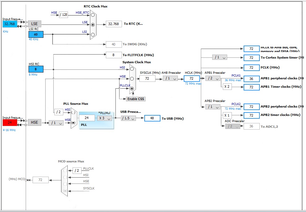
- Clock Configuration.jpg (113.49 KiB) Viewed 859 times
If the 101 is indeed identical to the 103, everything else is fine for a 24Mhz XTAL.
I do not know if there is any other difference between the 101 and the 103, but the USB hardware seems to be there, at least often enough.
It’s possible that there are different revisions of the 101, some with the usb and some without, same as some 103C8T6 have 64KB of flash, and some others 128KB.
It’s also possible that the 101 may not work reliably at those speeds.
If so, then you can try 48MHZ as mentioned.
Yes those lines are the ones you’d need to change
https://github.com/rogerclarkmelbourne/ … #L118-L122
If you look in
https://github.com/rogerclarkmelbourne/ … #L576-L591
This lists the bit settings for the various PLL multiplies
i.e 9 x is
RCC_PLLMUL_9 = (0x7 << 18),
and you need 3 x
RCC_PLLMUL_3 = (0x1 << 18)
(note that reg controls other stuff as well, so you’ll have to only change bits 18 – 22
I worked out how to recompile the bootloader and upload it using my STLink. I successfully recompiled and uploaded to an 8MHz blue pill and it worked.
I have also managed to compile a sketch (Blink n Count) for 24MHz operation by hacking ...\Arduino_STM32\STM32F1\variants\generic_stm32f103r8\wirishboards_setup.cpp
You could be running the main clock at 2 x 24 = 48 and the LED would blink or 4 x 24 = 96 and the LED would blink, but USB would not work with either of these.
However, you are also a crystal which is beyond the spec of the MCU, which says 16Mhz is the highest frequency you can use.
http://www.st.com/content/ccc/resource/ … 161566.pdf
Its possible that it may work sometimes with a 24MHz external crystal, but its potentially a problem waiting to happen if you don’t replace the crystal with one in the operating range for the MCU
[RogerClark – Mon Sep 04, 2017 5:41 am] – …you are also a crystal which is beyond the spec of the MCU, which says 16Mhz is the highest frequency you can use.
Ah, so it is. I’m sure I saw somewhere else that it was 8-25MHz but I can’t recall where. There is another IC on this board which uses a 24MHz crystal and I think the board designer has tried to reduce the BOM by using the same crystal for the micro.
[RogerClark – Mon Sep 04, 2017 5:41 am] –
If USB is not working, the most likely cause is that your main clock frequency is not what you think it is
Yeah that’s my thought too. The fact that USB runs fine in the sketch leads me to believe that something is still configured incorrectly in the bootloader.
[victor_pv – Mon Sep 04, 2017 3:50 pm] –
Can you post the changes you made to the bootloader to check if they are all that’s needed?
The only change I have made so far is to add an #ifdef for XTAL24M in hardware.c
    /* Configure PLL */

#ifdef XTAL24M

SET_REG(RCC_CFGR, GET_REG(RCC_CFGR) | 0x00010400); /* pll=72Mhz(x3),APB1=36Mhz,AHB=72Mhz */

#elif XTAL12M

SET_REG(RCC_CFGR, GET_REG(RCC_CFGR) | 0x00110400); /* pll=72Mhz(x6),APB1=36Mhz,AHB=72Mhz */

#else

SET_REG(RCC_CFGR, GET_REG(RCC_CFGR) | 0x001D0400); /* pll=72Mhz(x9),APB1=36Mhz,AHB=72Mhz */

#endif
SET_REG(RCC_CR, GET_REG(RCC_CR) | 0x01000000); /* enable the pll */
SET_REG(RCC_CFGR, GET_REG(RCC_CFGR) | 0x00010400); /* pll=72Mhz(x3),APB1=36Mhz,AHB=72Mhz */I think I posted the same hex value into the other thread that C_D has going
i.e His bit pattern was wrong.
[victor_pv – Tue Sep 05, 2017 12:42 am] –
This is wrong …
This should work (multiplies by 3):
SET_REG(RCC_CFGR, GET_REG(RCC_CFGR) | 0x00050400); /* pll=72Mhz(x3),APB1=36Mhz,AHB=72Mhz */
uint32_t v = 0x001D0400;// original  x9 bit pattern

uint32_t mask = (0B1111 << 18);// PLL mask

uint32_t pattern = (0x1 << 18);// x 3 PLL bit pattern
v = (v & ~mask);
v = v | pattern;
Serial.println(v,HEX);
Thanks so much guys. Sorry to have taken up your time with a silly mistake, but on the plus side I know a heap more about what makes Arduino for STM32 work now!
I hope you’re not using the bootloader etc in any mission critical or safety related application, because as stated in the repo this code should be considered as experimental. It was never intended to be used in commercial applications and you use it at your own risk
But the Arduino environment is perfect for me to quickly mash out new features to play with and test. I actually arrived here having come from MBed and the Nucleo range because a few years ago the USB serial implementation was buggy as hell. The Arduino for STM32 USB serial code has never missed a beat ![]()
However I don’t think they support the bootloader very well at the moment, nor changing the PLL for the crystal
You should also replace your crystal with an 8Mhz or 16Mhz, as 24Mhz is well outside the max operating frequency and could prove unreliable in mass production.
Most boards seem to use 8Mhz (perhaps as its the cheapest and most stable option)
I will look into the ST core too, I should at the very least have a play with it and see if its workable.
[victor_pv – Tue Sep 05, 2017 2:13 am] –
That looks like some sort of light controller, but can’t figure out what the THn pins would be other than thermistors.
Correct on both counts, it has both lights and thermistors, though the lighting isn’t really ‘controlled’ as such. It could just a easily be on a separate board but its all on one for testing.
Check the reference manual to see if the 24Mhz XTAL is supported if you use the /2 setting to the input of the PLL, perhaps 24 is over the theoretical limit of the PLL only, so dividing it by 2 before it enters then multiplying by 6 may be within the specs.
The data sheet says
“4-to-16 MHz crystal oscillator ”
I presume this to mean that the oscillator circuit e.g. the resonant components inside the MCU (mainly capacitors) are tuned to work in that range.
It probably means that if the MCU gets too cold or too hot, it won’t be able to start the osc
Victor
The board has a 7 port USB hub with one of those ports hard wired to the STM32. When connected to the host it allows communication with the STM32 via CDC and also 6 more downstream ports for connecting additional boards and or other peripherals (USB modem, bluetooth dongle etc). The host is a single board computer running Linux which provides network connectivity and runs a touch screen HMI.
Roger is correct it is for controlling industrial equipment, this particular version has 6 thermistor and 8 digital inputs (digital in, pulsewidth or frequency measurement), 4 digital outputs (digital or pwm) and 4 relays. It also has an AC power monitoring IC for tracking line voltage and current draw of the devices connected to those relays. I guess in essence its a glorified PLC with a more targeted feature set that’s not programmed in ladder ![]()
This particular combination of inputs and outputs probably wouldn’t exist on a final product, if it actually gets out of the prototype stage there would be a new PCB with just the required features for the application.


