I recently designed a custom STM32 board for an RS485 aplication. I was using an Atmega 168 before and I was having trouble with speed, so I decided it was time to move.
The board is simply a STM32F103C8T6 with an AS5048A magnetic encoder and a SN65HVD78 transceiver. It reads the encoder via SPI and sends the information to a dynamixel servo network, using the dynamixel protocol. I have the SWD pins to program it.
As I already have the code for the arduino IDE so I was thinking what should I modify on my code to port it. Another question I have is how I set the clock on the microcontroller (on AVR devices you use the memory fuses)? I’m using a 16Mhz crystal to reach the 72Mhz.
If you want, I can send the codes, the libs and the board schematic.
Here is a picture of the boards (I have two different models to fit in different places). I’m now soldering them and waiting for a few components to arrive.

I would apreciate a lot if someone could help me here.
Thanks!
I suggest to read at least the first chapters of Geoffrey Brown’s book from here: http://www.cs.indiana.edu/~geobrown/book.pdf
It is very important to know something about MCU, everything will be more easy.
As for Arduino compatibility, I can say that most of the libraries not related with hardware directly, will work almost untouchable. Everything is here, Serial, I2C, SPI. Some code with external Interrupts and hardware timers it is possible to need some rework.
        /* PLL_VCO = (HSE_VALUE or HSI_VALUE / PLL_M) * PLL_N */

#ifdef ARDUINO_STM32F4_NETDUINO2PLUS

int PLL_M = 25; // The NETDUINO has a 25MHz external oscillator

#else

int PLL_M = 8;

#endif

int PLL_N = 336;
/* SYSCLK = PLL_VCO / PLL_P */

int PLL_P = 2;
/* USB OTG FS, SDIO and RNG Clock =  PLL_VCO / PLLQ */

int PLL_Q = 7;
Its defined for each variant on the F1.
AFIK, no one else uses 16Mhz. Most boards use 8Mhz, though at least 1 STM32 board uses 12Mhz, and the GD32 boards I have use 12Mhz.
Just to get the board working with your existing crystal, just hack the generic f130c board variant file
https://github.com/rogerclarkmelbourne/ … _setup.cpp
However I dont know how you setup a multipler of 16 to give you 72mhz. Youd need mult of 4.5
This may be possible, but I’m not sure
The values are defined in
https://github.com/rogerclarkmelbourne/ … ries/rcc.h
But you’d need to look in the main reference for the F103 (google RM0008) or click here http://www2.st.com/resource/en/referenc … 171190.pdf
And look to see if its supported and if so , how you set it.
But in the long term, get some 8Mhz crystals ![]()
Open the MXBluePillF103C8.ioc file with STM32CubeMX and see how the 8 MHz clock configuration is set on STM32F103C8 MCU (Clock Configuration tab).
PLLXTPRE: HSE divider for PLL entry
Set and cleared by software to divide HSE before PLL entry. This bit can be written only
when PLL is disabled.
0: HSE clock not divided
1: HSE clock divided by 2
PLLXTPRE: HSE divider for PLL entry
Set and cleared by software to divide HSE before PLL entry. This bit can be written only
when PLL is disabled.
0: HSE clock not divided
1: HSE clock divided by 2
Now i’m really considering using 8Mhz crystals…
What’s the default configuration for the clock? I really dont want to hack things and hope for them to work. I dont have much time to finish this projetc (Brace yourselves, Robocup is coming!). If I use an 8Mhz crystal, the prescalers are already set to reach 72Mhz?
Use 8Mhz and you won’t need to change any code.
I suspect to use 16Mhz, the change you would need to make is just 1 bit in one register, but I’d need to read the big manual on the STM32F103 to work out which bit enabled the DIV 2 on the input clock
This is great! Now I can use 3225 16Mhz crystals which are ~5 times cheaper than the 8Mhz ones. Thanks!
This is great! Now I can use 3225 16Mhz crystals which are ~5 times cheaper than the 8Mhz ones. Thanks!
I think you’ll need to modify
STM32F1\cores\maple\libmaple\rcc_f1.c
Specifically
void rcc_configure_pll(rcc_pll_cfg *pll_cfg) {

stm32f1_rcc_pll_data *data = pll_cfg->data;

rcc_pll_multiplier pll_mul = data->pll_mul;

uint32 cfgr;

/* Check that the PLL is disabled. */

ASSERT_FAULT(!rcc_is_clk_on(RCC_CLK_PLL));
cfgr = RCC_BASE->CFGR;
cfgr &= ~(RCC_CFGR_PLLSRC | RCC_CFGR_PLLMUL);
cfgr |= pll_cfg->pllsrc | pll_mul;
RCC_BASE->CFGR = cfgr;
}
This is great! Now I can use 3225 16Mhz crystals which are ~5 times cheaper than the 8Mhz ones. Thanks!
And, on the STM32F4 (and others?) the internal clock that runs at power up (HSI) and runs all the C startup code, is 16MHz. Switching to the HSE clock, stays at 16MHz until (or if) the PLL is used. Note that the C startup code at HSI speed has the problem that if you have a lot of BSS to be zero’d and/or a huge number of initialized variables (other than const), that all runs at HSI speed and can slow the startup process – if that’s a factor. It is in one of my projects where the CPU has to get to the first line of code in main.c in < 10mSec.
I have an app on the ‘415 that runs at 16MHz for power up (hardware dictated) then on the PLL at 64MHz for most processing. When it’s time to number-crunch, I switch to 168MHz for a few hundred mSec. Then back. For the switch, I reprogram some of the peripherals (debut UART, SPI) so they will stay at the same line speed no matter the speed switching to 168 then back to 64MHz.
Point being, the 8MHz crystal choice has other factors that may apply to some cases.
But I still have some doubts about the programming. Today I tried to make the serial work (uploading thru ST Link and no bootloader) and I was not able to do it. My hardware uses the USART2 and maybe that was the problem. Can someone help me?
Im still very newbie with ARM controllers, i have just dealed with AVR devices.
Also had a problem with the PWM, I dont know why, but it seems to just turn the pin to a normal IO pin, I could not set the frequency for it, hope someone have an idea avout this also.
Thanks!
so Serial = USB Serial
Serial1 is Hardware serial 1
Serial2 is Hardware serial 2
etc
If you dont want USB serial, you will need to change boards.txt to remove the inline definitions for the USB serial stuff
or try uploading via Serial, as that upload mode does not have USB serial enabled
so Serial = USB Serial
Serial1 is Hardware serial 1
Serial2 is Hardware serial 2
etc
If you dont want USB serial, you will need to change boards.txt to remove the inline definitions for the USB serial stuff
or try uploading via Serial, as that upload mode does not have USB serial enabled
Not in “Ports” serial ports
Not in “Ports” serial ports
OK, the name of Volume created by ST-Link is always something with 401RE, but it works. Do you mean that every Nucleo’s stlink V2.1 is working only (as storage device) to specific variants of STM32 family?
OK, the name of Volume created by ST-Link is always something with 401RE, but it works. Do you mean that every Nucleo’s stlink V2.1 is working only (as storage device) to specific variants of STM32 family?
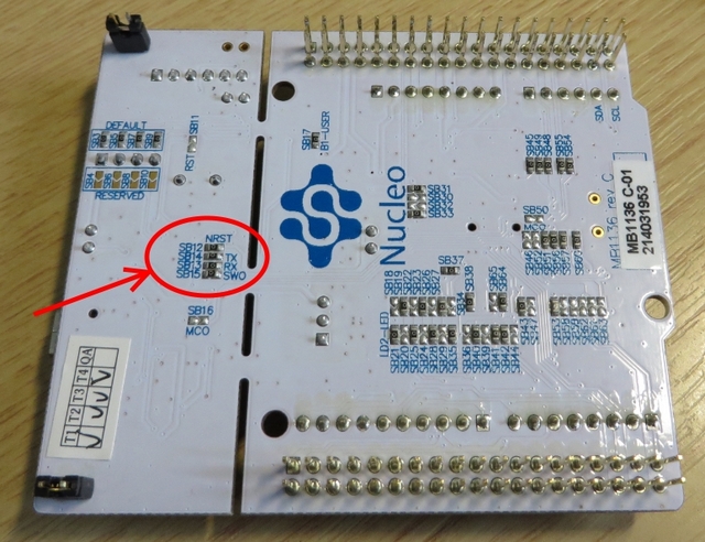
- nucleo-board-bottom-side.jpg (253.3 KiB) Viewed 1379 times
Just remove the two jumpers on CN2 (see photo). The only problem I had with Nucleo-STLInk is that RESET pin is required for reseting the target system (or you have to reset manually by button or other way) . Note that VCC cannot power the target board from ST-Link (unlike the cheap ST-Link Dongles), is only for sensing the target voltage, but in Nucleo-STLink is NOT used. Note the TX & RX at CN3, these signals go to USB-CDC.
The price of the board is so low and I think it is possible for someone to buy it, just for the ST-Link part (and keep the rest as a bonus).
Just remove the two jumpers on CN2 (see photo). The only problem I had with Nucleo-STLInk is that RESET pin is required for reseting the target system (or you have to reset manually by button or other way) . Note that VCC cannot power the target board from ST-Link (unlike the cheap ST-Link Dongles), is only for sensing the target voltage, but in Nucleo-STLink is NOT used. Note the TX & RX at CN3, these signals go to USB-CDC.
Re:Usb mass storage
The STM32F103 does not have any built in USB profiles, ( unlike the F4).
You can write code so that its any form of USB device you want, but you have run code in the MCU to do this.
If you feel like writing a mass storage bootloader, please go ahead, but remember you wont be able to use the HAL or CMSIS etc as the code needs to be ultra small ( less then 0x2000 to be comparable with the existing DFU bootloader)
V2.1 adds some very important features like mass storage upload and USB/Serial passthrough, as I understand nobody has cloned the V2.1 (this is included on all Nucleo boards) as all Chinese clones support V2 operations.
If we compare the code size of BlackMagic (which is also a debuger/serial passtrough device), I dont think that would be possible to include this functionality in the code memory of a typical F103C8 as bootloader (and to have spare memory for a real application)
But I think the point is that the STLink (even V2) is not intended as a bootloader its a debugger, and would severely limit the amount of available code space left for applications.
The BMP is pretty much the same as the STLink, except without mass storage, and the BMP is quite large as well (i.e it would not be useful as a bootloader)
I think a mass storage bootloader would be great to have, but as using the HAL etc or any other lib e.g. libopencm3 would be impractical due to size, I doubt its practical
usb is not used.
STM32duino bootloader is usb based, but you may use ST-LINK/J-LINK, or serial upload.

