I tried this but it does not seem to be working. Always get 3.3V
pinMode(LCD_LED, PWM_OPEN_DRAIN);
The pins usually have got an ESD protection circuit, 2 or 4 Si clamp diodes. The F103 refman shows 2 diodes, so when pulling a resistor up to 5V on one side, the output will stay at Vdd(3.3v) + Vf_diode(0.3..0.5V). The current flows from 5V–>load resistor–>diode–>3.3Vdd.
Hmm, when digging into the refman (gpio pins), on the schematics there is also a “VDD_FT” as an option connected to upper clamp diode with an remark:
VDD_FT is a potential specific to 5-Volt tolerant I/Os and different from VDD
So it seems 5V should work with open drain if the VDD_FT is activated.. ![]()
Another remark:
FT = Five-volt tolerant. In order to sustain a voltage higher than VDD+0.3 the internal pull-up/pull-down resistors must be
disabled.
see
https://github.com/rogerclarkmelbourne/ … tal_f1.cpp
BTW.
If this works, I am sure a lot of people would be interested, as I know other devices e.f. 7 seg red LED displays that only work if you have 5 V data lines
Errata for STM32F103XX – document ES096
http://www.st.com/content/st_com/en/sup … rata_sheet
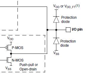
- GPIO output.JPG (11.66 KiB) Viewed 4295 times
If you are powering the whole thing from an external 3.3V supply and have no other source of 5V, I agree, the only option is to use a charge pump.
Depending on how much current you need, I suppose you may be able to use the PWM on one of the pins to generate the square waves for the charge pump, but it may take too much current for a single GPIO pin (and of course you would need various descrete components to build the charge pump
Moreover an internal charge pump which may limit voltage to 5V with ie LED currents is a nogo
There must be a different trick with the VDD_FT, but nobody knows it..
Anyhow, I would rather recommend to OP an npn transistor driving the power mosfet (and invert the PWM polarity).
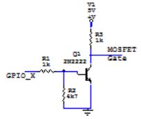
- driver mosfet.JPG (4.56 KiB) Viewed 4287 times
If the pin is set to OUTPUT_OPEN_DRAIN cant it be pulled high by an external pullup from 5V if the pin is 5V tolerant ?
As you can see from the STM GPIO schematics above, there is the D1 (on top) diode, which limits the output voltage (also in OPEN DRAIN MODE) to Vdd+0.3V, or, VDD_FT+0.3V (where 0.3V is the forward voltage of D1 for small currents).
If VDD_FT would be 5V, than the max voltage you may see on the OPEN DRAIN output loaded with a reasonable valued resistor would be 5V+0.3V (when OD gpio set to HIGH, and internal pullup/down resistors are disabled).
With this:
void setup() {

// put your setup code here, to run once:

pinMode(PB8, OUTPUT_OPEN_DRAIN);

}
void loop() {
// put your main code here, to run repeatedly:
digitalWrite(PB8, LOW);
delay(2000);
digitalWrite(PB8, HIGH);
delay(2000);
}
Pito: Thanks for the info. Will try that. That is actually what I wanted originally. But I’ll need to try PWM_OPEN_DRAIN instead.
Yes you’re the first ![]()
(when OD gpio set to HIGH…..).
With Open Drain you get High or Low as well, it is expected there is a pull-up at the pin.
There is no HighZ with a pull-up wired.
But I’ll need to try PWM_OPEN_DRAIN instead.
const uint8_t PwmLeikkYA = PB8;

....

#define __LEIKKURITERAN_NOSTO_NOPEUS_  127

....

pinMode(PwmLeikkYA, PWM_OPEN_DRAIN);

....

pwmWrite(PwmLeikkYA , __LEIKKURITERAN_NOSTO_NOPEUS_ );With Open Drain you get High or Low as well, it is expected there is a pull-up at the pin.
There is no HighZ with a pull-up wired.
