Did anyone try using this library https://github.com/TMRh20/RF24 (or its older version https://github.com/maniacbug/RF24) for nRF24L01 devices on the STM32F103?
It seems to compile without errors for this board but I do not have the device yet to actually test it. Also, by looking at the code I could not figure out if this library can work with the secondary SPI.
Thanks!
Adrian
RF24Mesh and MySensors are nice because they take care of a lot of the setup stuff so you can just add and extend (MySensors is specific to adding sensors to various Home Automation solutions)
If so, i have a few of these as well, but i never had much success with them, even on AVR.
The range seemed to be quite low, and would not go though many internal plasterboard walls.
1. Fixes module RF24.cpp for maple mini was in the function void RF24 :: csn (bool mode)
  #if! defined (SOFTSPI)

_SPI.setBitOrder (MSBFIRST);

_SPI.setDataMode (SPI_MODE0);

_SPI.setClockDivider (SPI_CLOCK_DIV2); // Lower frequency !!!!!

#endif
Here’s some links that might be new to you.
Radios – in the US, this is the main distributor – they do accommodate low quantity orders as a rule. HopeRF is a decent Asian board maker; they use radio chips from two US manufacturers.
http://anarduino.com/
This open source Arduino-compatible protocol stack is in C++. I and others have made a few simple changes to run it on STM32’s.
At the bottom of this protocol stack are drivers for most of HopeRF’s boards, and radio boards from other vendors too.
http://www.airspayce.com/mikem/arduino/RadioHead/
The RFM69HW module placed on an MCU board (H for high power) – I’ve used lots of these. No. America, use 902-928MHz band; in the EU and some other places, 868MHz. The 433MHz band exists in the US and elsewhere but the regulatory limits on transmitter duty cycle are severe.
As in any data radio, the range is governed by:
- Channel width (narrow = better range)
- Modulation rate (lower = better range, i.e., don’t try 50-100Kbps and expect longest range)
- FM Modulation index (for these mostly FM/GFSK radios)
- Transmitter power
- Antenna gain(s) from choice of antennas – omni-directional or directional depending on topology of the network.
- Terrain and other non-line-of-sight impairments.
For a line of sight path, we can easily calculate the achievable range (as a link budget). I have a spreadsheet I use do to that,.
For non-line of sight, experience tells one what to expect. As well as trials.
A pair of RFM69HWs (100mW) with say 30Kbps or so, conservative modulation index, dangling-wire antennas, elevated to about 6 ft., line of sight, will give a reasonable error rate at 100m. In any link design, you want 10+ dB of fade margin (excess received signal strength).
Radiohead’s stack includes an option for “reliable datagram” mode.. meaning there are CRC checks and retransmissions for error correction.
Other protocols include unreliable datagrams (like UDP), fixed routed network, and mesh-routed network.
There are models with more transmit power and external antenna, you need separate power like an ESP8266. They claim to have a long range, but not long as an xbee. If you use directive antennas you can reach a very long range.
I have RF24L01 cheap modules and subGHz radio modules but never tested them for long distance.
<…>
I have RF24L01 cheap modules and subGHz radio modules but never tested them for long distance.
thanks for the painful flashback…
when we remodeled last year, we found the bathroom was Drywall over plaster over metal lathe over more plaster (almost 1″ thick). It took a sawzall with a Diablo blade to get most of it out and many of the corners I had to attack with an angle grander because they used extra metal lathe as reinforcement.
As for the RF-24 library, I’m still working on getting my STM32s sorted and need to look at the library. I’m sure it’ll work with a few changes as others have gotten the NRF24’s working. I really want the mesh mode going because it’s the easiest for my to work with.
I haven’t really had distance issues within the house with the on-PCB antennal. There is a p version wit PA+LNA and an external antenna (http://www.elecfreaks.com/wiki/index.ph … PA_and_LNA). They are rated at 1000m @ 250 kbps in open air with a 2db antenna.
The ping pair sketches work great. The only thing that is weird is, on the AVR chips, you can leave the sender on and it works fine. On my port, you have to call stopListening() before sending a packet and call startListening() after sending, even if you are not listening for anything. This may not always be required, but in my program, I am receiving an acknowledgement packet with data, and that is all I have tested other than the examples which do this anyway. I think it is something with the SPI ending a transaction or something, but I have not looked into it much. Otherwise, it hang up. It does not do this behavior on AVR.
I can post my modified version on github if you want. I am not planning on fixing the bug soon because I decided to go with a different sub ghz radio from hope RF because I need greater distance and more wall penetration for my project.
I have a friend that swears by: http://lowpowerlab.com/moteino/
I guess it really depends on what one intends to do at 2.4G… the ESP8266 is being utilized in my house (master GPS datagram transmitter is in the attic and the UDP receivers work anywhere in the house and basement and around the perimeter of the 1/3 acre lot. But, I really have not tried TCP to see what a more reliable form of communication would provide in the same space.
http://www.hackster.io/rayburne/tardis- … server-gps
Ray
<…>
Which module are you using? Just the standard trace antenna?
Just to be clear, you are not going through your router, just ESP8266 to ESP8266 correct?
Forum member Martin Ayotte (martinayotte on ESP8266.com) has some published peer-peer code. My UDP example which was linked earlier can also be TCP just by changing the protocol invocation.
http://www.esp8266.com/viewtopic.php?f=27&t=4080#p23577 (must be logged-in to download)
You may want to run a wifi scanner and find a channel that is not being used by other routers in the vacinity, as this can cause interferance and loss of range (but it doesnt seem to make much difference)
If you need longer range, you would have to use lower frequencies e.g. 433MHz or 915MHz etc, but using devices for those bands, e.g. nRf905 and RFM69 is much lower data rate etc etc
<…>
Those examples are now pretty old, but they still a good way to start …
srp
Last I remember, printf is not implemented but sprintf is implemented.
Ray
Last I remember, printf is not implemented but sprintf is implemented.
Ray
https://github.com/rogerclarkmelbourne/ … .h#L66-L69
smiley supplied is just not big enough
stephen
Unfortunately, I can’t even remember starting it ![]()
Well, actually a vague recall looking at this.
I think I had some issue redirecting the output of printf putc into the USB Serial.
It was probably a case of running out of time and having more pressing things I needed to do
If I get time (A big if), I will take a look at what the ESP8266 does and possibly be able to learn from that (albeit they are sending chars to the hardware via the SDK, not to the virtual serial buffer, but surely it must be very similar !)
I’ve actually looked at ESP version of printf, and then look at STM32 to get the actual discovery of the job was started.
It is a bit similar, but as you said, we need to figure out possible impact, and if none, then enabling that code by default.
On ESP, here how it looks (see that it is limited by MTU size 1460) :
size_t Print::printf(const char *format, ...) {

va_list arg;

va_start(arg, format);

char temp[1460];

size_t len = ets_vsnprintf(temp, 1460, format, arg);

len = print(temp);

va_end(arg);

return len;

}
Umm.
OK. That looks like a bit of a bodge.
I will need to see what
ets_vsnprintf() does
I’m sure I’ve read something about somehow redirecting the PutC output from vaprintf etc, so that it goes to whichever function you want
But I think that’s as far as I got.
Edit.
It looks like we’d need to define put_ch()
e.g. I think this link has some information
I think a possibility is to look again to the genius Paul Stoffregen and his teensy project and how he solved the “printf” “feature”:
https://github.com/PaulStoffregen/cores … /Print.cpp
Maybe I have some time to play with that…
>EDIT< Ok, it seems, like Roger did already take the teensy part for printf. Ok, didn’t got the library working (totally no response, but compiling is ok, how I hate that…). So at first, I’m going to check out the other nrf24 library (enrf or something from energia) to be sure, that the module is working well.
It looks like Paul is calling vdprintf, which he is passing a pointer to the Print class, so that vdprintf would treat the Print class as some sort of File stream (But i may be wrong about how it works)
I presume vdfpintf calls the write function (again I’m not sure)
But it would definitely be worth investigating
Little offtopic:
A really MUST have little helper for the nrf24 modules (only 60 Cent (Euros)):
http://www.aliexpress.com/item/New-Sock … 27557.html
With this little guys (ok, ok can solder it easily by yourself, but for 60 cents…) all my problems with the modules are history (remember, that I’m working on many different MCU devices, so I cannot remember all max mA for 3.3V, I’m lazy and I’m a fan of voltage converters for every different module)).
I remember looking at it, over a year ago, but I can’t remember why it wasn’t working
I think possibly its something to do with some functions like putc() , or possibly its called putch() not being implemented
Or if they are implemented they don’t do whats required.
I don’t think I could work out how to setup the linkage to these character writing functions.
I’m sure its documented somewhere on the web e.g.
small edit: The enrf24 scanner demo looks like working fine, but the rx/tx demo doesn’t. Won’t get any connection between two minis. (I think the RX demo code is the problem, hangs up)
Attached a working example as used with my home sensor network.
Hope it helps.
Regards.
-JBF.
Attached a working example as used with my home sensor network.
Hope it helps.
Regards.
-JBF.
Perhaps I should add it to the repo
I don’t think this library is ready for the main repo, I think in the main repo should be only libs they are 100% tested and proofed.
But (!):
Maybe it would be a good idea to make an folder on github for those “not 100% libs? So we can refer every time to this github link and we can collect all this “unfinished” but very useful libs out there in the forum and/or on different github accounts. Otherwise we would loose many potential codes over the time….
Maybe a good github name would be “User libraries [not verified]” or something. So the user can do a “pull request” and you can just accept it without thinking of compatibility issues or something. If a library is tested by several users it could be dragged into the main repo?
Yes, it permits a holding grounds and archive, but
It also permits an area where the sources are unknown, the working state is unknown, and the quality unknown.
My fear is that traditional 8-bit to 32-bit porting efforts will wind-up in an incomplete state and just become a junkyard of digital goop.
We have always stressed on the forum that the person needing the library should manage their own port and engage the forum for specific issues. Thus, when the library is complete and is working satisfactory, a pull request can be issued to Roger. We now have working code and some issues that can be documented.
Just my thoughts,
Ray
Could You please add an example of two way communication like a ping-pong for tx and rx devices?
Thanks in advance
Could You please add an example of two way communication like a ping-pong for tx and rx devices?
Thanks in advance
radio.setPALevel(RF24_PA_LOW)
I always use this adapters:
https://www.aliexpress.com/item/10pcs-N … 18663.html
radio.setPALevel(RF24_PA_LOW)#include <RF24Network.h>
#include <RF24.h>
#include <SPI.h>
#include <DHT.h>
// The DHT data line is connected to pin 2 on the Arduino
#define DHTPIN 2
// Leave as is if you're using the DHT22. Change if not.
//#define DHTTYPE DHT11 // DHT 11
#define DHTTYPE DHT22 // DHT 22 (AM2302)
//#define DHTTYPE DHT21 // DHT 21 (AM2301)
DHT dht(DHTPIN, DHTTYPE);
// PIR variables
byte pirPin = 9;
int pirCalibrationTime = 30;
// Photocell variable
byte photocellPin = A3;
// Magnetic Door Sensor variable
byte switchPin = 12;
// Radio with CE & CSN connected to pins 7 & 8
RF24 radio(7, 8);
RF24Network network(radio);
// Constants that identify this node and the node to send data to
const uint16_t this_node = 1;
const uint16_t parent_node = 0;
// Time between packets (in ms)
const unsigned long interval = 1000; // every sec
// Structure of our message
struct message_1 {
float temperature;
float humidity;
byte light;
bool motion;
bool dooropen;
};
message_1 message;
// The network header initialized for this node
RF24NetworkHeader header(parent_node);
void setup(void)
{
// Set up the Serial Monitor
Serial.begin(9600);
// Initialize all radio related modules
SPI.begin();
radio.begin();
delay(5);
network.begin(90, this_node);
// Initialize the DHT library
dht.begin();
// Activate the internal Pull-Up resistor for the door sensor
pinMode(switchPin, INPUT_PULLUP);
// Calibrate PIR
pinMode(pirPin, INPUT);
digitalWrite(pirPin, LOW);
Serial.print("Calibrating PIR ");
for(int i = 0; i < pirCalibrationTime; i++)
{
Serial.print(".");
delay(1000);
}
Serial.println(" done");
Serial.println("PIR ACTIVE");
delay(50);
}
void loop() {
// Update network data
network.update();
// Read humidity (percent)
float h = dht.readHumidity();
// Read temperature as Celsius
float t = dht.readTemperature();
// Read temperature as Fahrenheit
float f = dht.readTemperature(true);
// Read photocell
int p = analogRead(photocellPin);
// Testing revealed this value never goes below 50 or above 1000,
// so we're constraining it to that range and then mapping that range
// to 0-100 so it's like a percentage
p = constrain(p, 50, 1000);
p = map(p, 50, 1000, 0, 100);
// Read door sensor: HIGH means door is open (the magnet is far enough from the switch)
bool d = (digitalRead(switchPin) == HIGH);
// Read motion: HIGH means motion is detected
bool m = (digitalRead(pirPin) == HIGH);
// Headers will always be type 1 for this node
// We set it again each loop iteration because fragmentation of the messages might change this between loops
header.type = '1';
// Only send values if any of them are different enough from the last time we sent:
// 0.5 degree temp difference, 1% humdity or light difference, or different motion state
if (abs(f - message.temperature) > 0.5 ||
abs(h - message.humidity) > 1.0 ||
abs(p - message.light) > 1.0 ||
m != message.motion ||
d != message.dooropen) {
// Construct the message we'll send
message = (message_1){ f, h, p, m, d };
// Writing the message to the network means sending it
if (network.write(header, &message, sizeof(message))) {
Serial.print("Message sent\n");
} else {
Serial.print("Could not send message\n");
}
}
// Wait a bit before we start over again
delay(interval);
}
How and what kind of contacts (PIN) to connect the nrf24l01 to the Board STM32F407VET6 (black) to make it work ?
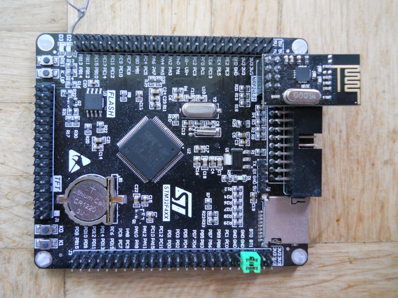
Is there a working example to work on SPI3 with this Board ?
// Radio with CE & CSN connected to pins 7 & 8
RF24 radio(7, 8);
How to write for this Board this line ?
What pins should I write ?
I am new on this site and posted a question about RF24 and Maple Mini.
I loaded the example of above and the added the libs to my PC and built the sender/receiver.
Everything seems okay (besides some warnings of redefinitions during compiling).
But the output of the receiver is totally rubish; even when I switch the sender of, the receiver produces the same random numbers
Could it be that the SPI or RF24 libraries have changed in the meantime or that I use the wrong ones?
thanks in advance
John
Maybe a loose wire?
Power supply 5V <-> 3.3V issue?
mine are on the actual device pcb. i.e. moves with the device
stephen
