I’m new on this forum (and of course with 32 bit microcontroller) and I want some help to unlock (!?) my generic STM32F103 Bluepill.
I upload the bootloader generic_boot20_pc13.bin onto uC with both BOOT0 and BOOT1 jumpers on LOW level.
Everything went fine, even the scketch “blink”. Two days after, I compile and upload a scketch to drive HX8340 LCD(3.3V) using SPI1 pins.
From this point everything was blown in the wind. The STM32 board is not recognized by STLink programmer, neither on UART1 ports using demonstrator software from STMicro. Strange thing is that with the to jumpers on LOW level when I push RESET button PC13 LED is blinking initially quick, then slower and then not at all.
Is there a solution to bring my board to life, I mean to an usable state?
Thank you
P.S.: I use Win7 OS
I am familiar with 8 bit microcontroller not with 32 bit microcontroller. Now I begin to learn and the first contact was harsh and “painful”.
Honestly, I do not understand how was possible to lock (!?) this microcontroller. I used the scketch from STM examples who explain how to use SPI nothing more!
L.E.: Testing the output of STLink clone reveals that I have clock signal but nothing on data IO pin. It is normal?
First with BOOT0 on LOW level and STLink utility:
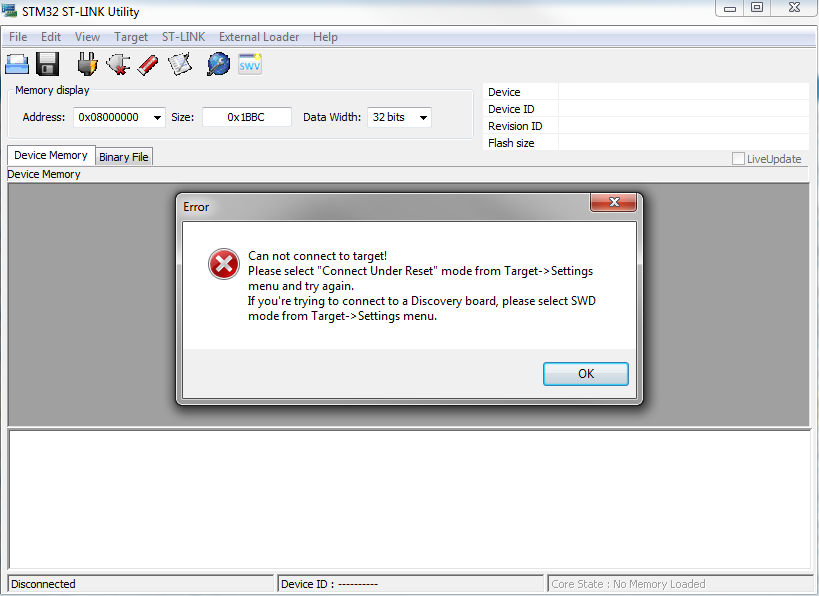
- SnapShot1.png (46.56 KiB) Viewed 2277 times
But I think this not involve lack of connection with serial adapter or STLink V2
They are so useful, and so cheap that I now have a couple of them. I did manage to confuse myself on one occasion by trying to use the st-link connected to the target board with the GND pin disconnected. Took me about half an hour of head scratching, and I was about to write of the board when I noticed I only had three wire connected instead of four. I was powering the target from the ST-Link, so needed GND, SWCLK, SWDIO, and 5V
Still I cannot debug or connect to one of the programmers (serial or STLink V2 clone)
Then, connect the ST-Link to your PC and run the st-link utility. Normally, your blue-pill will be recognized by your st-link utility if you press “connect to the target” button.
Still I cannot debug or connect to one of the programmers (serial or STLink V2 clone)
Change the setting in the STLInk program to allow this
Press and hold reset on the board
On the STlink program tell it to connect
Release the reset button.
(Note, sometimes timing can be a bit critical with this, though with “Connect under reset” it should not time out while waiting)
Either way, its normally possible to recover the board
If you can upload a sketch, you could also hack to core to enable STLink pins (I forget exactly where this in the code but its controlled depending on if you use the bootloader so its fairly easy to find if you search the core codebase for places that use the bootloader defines)
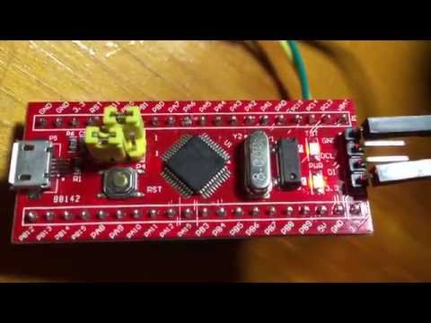
First of all I want to thank you all for advices. To be specific, the fotos I posted was made using for the second one USB to TTL convertor FT232 based, connected to USART1 and jumper for BOOT0 on “1” logic and ST DEmonstrator software. At this time I tried with RESET button pressed, then without RESET pressed with same result as in picture.
In the first picture I used STLink utility with STLink V2 clone (with upgraded firmware), changing each time the settings to connect to blue pill (from Normal, to Hot plug to Connect under reset), but the results were the same as in picture posted.
At every time the connection were correct using – from UART to board- Vcc to 5V, Rx to TX, Tx to Rx and GND to GND, respectively from STLink clone to board SWDIO to DIO, SWDCLK to CLK, 3.3 V to 3.3V and GND to GND.
I will check also voltage regulator to see what is the output.
In the mean time I checked board.txt to see if there are settings to disable SWD pins but found that are OK, according to one post of Roger Clark I think.
I use Win7 OS, so I am not familiar with UNIX/LINUX or other OS.
Thank you all
i.e instead of
genericSTM32F103C.menu.upload_method.DFUUploadMethod.build.upload_flags=-DSERIAL_USB -DGENERIC_BOOTLOADER
STLink was unable to find the chip until I used the STM32 ST-LINK Utility, then in setting choosed “Connect Under Reset” (Mode), then, after connection, blanked the chip. After done that the IDE was able to program the chip. I simply don’t remember wich sketch was in the chip.
STLink was unable to find the chip until I used the STM32 ST-LINK Utility, then in setting choosed “Connect Under Reset” (Mode), then, after connection, blanked the chip. After done that the IDE was able to program the chip. I simply don’t remember wich sketch was in the chip.
Best regards
Best regards
except the diodes!
(I burned another on my RET board while wrong connecting +5V and GND to my ST7920 LCD – those on board SMD diodes are really weak!
<…>
(I burned another on my RET board while wrong connecting +5V and GND to my ST7920 LCD – those on board SMD diodes are really weak!
Are you keeping score?
Ray
Are you keeping score?
Ray
However I recovered it as follows…
# Install the latest OpnOCD – then plug in your st-link and ensure it is connected correctly to the target.
# Run OpenOCD as follows (paths may vary depending on your installation).
sudo /usr/local/bin/openocd -f /usr/local/share/openocd/scripts/interface/stlink-v2.cfg -f /usr/local/share/openocd/scripts/target/stm32f1x.cfg
# In a second window telnet to the openocd debug session on port 4444
telnet localhost 4444
# At this point, depending on how badly its brains are scrambled, you may need to press reset and type halt a number of times to successfully halt the CPU.
# Note: The example is for an STM32F103C8T6 – this board here as it happens -> http://wiki.stm32duino.com/index.php?ti … Smart_V2.0
> halt
target state: halted
target halted due to debug-request, current mode: Handler HardFault
xPSR: 0x41000003 pc: 0x080001b4 msp: 0x20004fe0
> stm32f1x mass_erase 0
stm32x mass erase complete
> stm32f1x unlock 0
Device Security Bit Set
target state: halted
target halted due to breakpoint, current mode: Handler HardFault
xPSR: 0x61000003 pc: 0x2000003a msp: 0x20004fe0
stm32x unlocked.
INFO: a reset or power cycle is required for the new settings to take effect.
# Now power off and back on… and you should, with a bit of luck have a clean system that you can flash code to once more.

