In the last 2 days xC000005 and me have completed successful prints with Marlin for STM32F1, with the stm32duino-libmaple core, he printed a cat, and I printed a little Yoda-Budha.
During tests I was able to get about 50000khz pulses as max speed, which seems inline with other 32 bit platforms, and much faster than most printers should ever need. Which means at slower rates we have quite a few CPU cycles left to do other things.
We haven’t start with the LCD parts, but so far ADC, steppers and sdcard work, so printing from a computer is fully functional.
UPDATED 07/07/2017:
First version of my port to libmaple based cores. Should work on an F4 too, but so far I have just tested it with the F1, and only that it runs and there is serial communication, but not the steppers driving or the SDCard.
Compiled with Sloeber 4.1 and gcc 4.8.3. Should compile in the Arduino IDE but not tested.
I have tested it with an RCT6 MCU, but should fit fine in a maple mini as far as RAM and Flash
https://github.com/victorpv/Marlin-STM32-libmaple
==============================
Original post.
I’m starting this new thread to document the effort of porting Marlin to stm32 arduino cores.
-Shield with stepper connections etc, RAMPS can be modified:
-Boards: too many to list
- My effort will go first to libmaple. Chriss Bar has a version based on STM32GENERIC core. Both cores work on some F1, F3 and F4 MCUs
-Software:
There are at least 2 ports running in STM32.
- STM official one for their EVAL board. Doesn’t use arduino core. Uses the HAL.
Based on Marlin 1.1.0 RC7
https://github.com/St3dPrinter/Marlin4ST - Chriss Barr port. Uses the HAL. Nucleo 446 board.
Based on Marlin with HAL Bugfix fork.
Chriss said in a github conversation he has a more recent code that will try to upload in the next few days.
https://github.com/chrissbarr/Marlin/tr … Fix-F446VE
My plan:
Take Chriss code and make it compile in sloeber.
Once so, take it to Danieleff core, and make it compile and resolve any issue.
Test it with a Nucleo board and generic boards.
Add HAL for libmaple core
All the above should be feasible from a first look at the code.
We already have:
-Arduino compatible pin functions.
-Arduino compatible spi functions.
-Arduino compatible ADC functions (with more resolution, may need to trim)
-PWM functions (even if with some different parameters and setup than Arduino, still same functionality or more)
What needs to be done:
-Go thru each file in the HAL and modify/optimize for stm (just a few things)
Stepper control
Temperature probes and hotbed control
Memory usage.
Pin access.
Timers setup and usage.
Do you envisage this being doable with say a bluepill or MM, a hand full of ebay stepper motors and stepper driver boards?
[ahull – Thu Jun 29, 2017 4:45 pm] –
Hi. This might provide the motivation I need to start constructing a 3D printer from scratch, which is a project I have been meaning to undertake for a while.Do you envisage this being doable with say a bluepill or MM, a hand full of ebay stepper motors and stepper driver boards?
I haven’t done a pin count, but I think a maple mini will most likely do, at least for a printer with 1 extruder and 3 axis.
Quick pin count:
4 steppers, 2 pins each, 8 pins.
Bed heater and thermistor: 2 pins. (1 ADC + 1 PWM)
Extruder heater and thermistor: 2 pins (1 ADC + 1 PWM)
SD card if needed 4-5 pins (don’t remember of the top of my head).
Display: There are several options, I think common ones take 4-6 pins.
USB port: 2 pins
Optional: serial, connected to wifi printer bridge, 2 pins.
All this run in an AVR, I dont see how it wouldn’t run in a mini as far as RAM and Flash.
Optional hardware not critical to have:
-Rather than use a bunch of pins for an LCD, use the same SPI as the card and 1 extra CS pin, but this would involve writing an LCD interface.
-Serial not needed, but would be nice to connect an ESP8266 programmed with this (I have compiled and uploaded it with Eclipse/Sloeber successfully):
https://github.com/luc-github/ESP3D
-Sd card interface: You can instead print from the host. I actually never connected my printer to a host, ever, just print with the sd card so I dont have to keep a host connected for a 4 hour print.
I think this sounds like a pretty useful idea.
[ahull – Thu Jun 29, 2017 7:26 pm] –
Sounds doable, don’t forget, we get USB serial on a MM or Bluepill which you don’t get on an AVR.
I think this sounds like a pretty useful idea.
I think so. Not only doable, but we should end up with a nice controller, and using an RET6 MCU we should have ram and pins to spare for any expansion, but even the CB ones should fit the current Marlin.
Do you want to help spread the load?
I recently bought a 3d printer for my kids, which I am enjoying much more than then, specially building it up, so I can give you some advise on parts and what not.
EDIT:
From reprap.org
Firmware binary size between around 50 kB and 100 kB, depending on options.
- sd card
sd card detection switch
serial 1
USB
3 axis steppers
3 extruder steppers (or any conbination of the 6, such as 4 axis and 2 extruders
3 extruders temp probes
3 extruders heaters
bed temp probe
bed steppers
2 CS pins for SPI, for sdcard and a display
1 pin left (could be used as CS for a touch panel in SPI)
PB2 and PB8 not used (can be used as outputs once the mcu is booted, so we should be able to use them)
I haven’t looked in detail to all the peripherals needed, but I think we have enough timers,and definitely enough PWM pins.
[ahull – Thu Jun 29, 2017 4:45 pm] –
Hi. This might provide the motivation I need to start constructing a 3D printer from scratch, which is a project I have been meaning to undertake for a while.Do you envisage this being doable with say a bluepill or MM, a hand full of ebay stepper motors and stepper driver boards?
imho a simplier approach is to buy one of those cheap 3d printer kit and later swap the controller board
i’ve been contemplating creating a delta-3d from scratch but later find that it would be too much efforts to create the individual components to the precise dimensions and the total costs of purchasing the parts say from ebay actually exceeds that of buying a kit which these days go for $200 and even below.
some of those things has been discussed in this thread
http://www.stm32duino.com/viewtopic.php?f=45&t=2082
my thoughts are that we should perhaps target the f407vet6 or zet6,zgt6 board directly rather than stick with stm32f103 (though it is a possibility as well). the main thing is that m4 (f407) has 2 fpu in the cores and that would significantly speed up path computations and of course the f407vet boards has a good number of gpio pins to do all that interfacing and has a good amount of sram and flash to play with. in addition a good number of those f4 boards from ebay has that micro sd card slot built on board which is an additional convenience
for stm32f103 the ‘common’ boards apparently are blue pills & maple mini while for the bigger boards e.g. vet and zet, the price differential pull so narrow compared (some priced same or higher) to say f407vet6 black. it would literally make sense to simply get f407 boards directly in that case given the much higher performance
with f407 i’d even envision that one day it may be possible to simply send it an ‘STL’ 3d model file, the f407 do all that slicing & 3d print it on the fly! that’s possible due to the fast fpu
http://forums.reprap.org/list.php?415
this thread would actually make sense to belong ‘there’ given it is about running Marlin on stm32
but the forumers there would likely be less familiar with available stm32 boards and features ‘out there’ and its ‘technicalities’ compared to us here
we could also get various tips / from the ‘3d printing people’ as beyond just the electricals / electronics. 3d printing is really a domain on its own
things like dealing with bed leveling, extrusion speed, head movements acceleration / deceleration, delta 3d movements, types of materials and the 3d printing problems etc are really quite specialised domains of knowledge which the ‘3d printing experts’ are probably familiar with
the other idea is to start with RAMPS
http://reprap.org/wiki/Arduino_Mega_Pololu_Shield
as the interface board as this board and the pololu motor control socket modules is actually sold on ebay and readily available (decently low costs as well)
[victor_pv – Fri Jun 30, 2017 4:00 am] –
I did a pin count and with a maple mini we should have enought pins for the following:
- sd card
sd card detection switch
serial 1
USB
3 axis steppers
3 extruder steppers (or any conbination of the 6, such as 4 axis and 2 extruders
3 extruders temp probes
3 extruders heaters
bed temp probe
bed steppers
2 CS pins for SPI, for sdcard and a display
1 pin left (could be used as CS for a touch panel in SPI)
PB2 and PB8 not used (can be used as outputs once the mcu is booted, so we should be able to use them)I haven’t looked in detail to all the peripherals needed, but I think we have enough timers,and definitely enough PWM pins.
there could be up to 6 end stops (limit switches) in addition, if we use 1 gpio pin for each, that alone takes 6 pins
and more than likely we’d still want to interface our ILI9341 LCD display, i think the total pin count considering all that would lead us to run out of pins on blue pill or maple mini
There is already a port for STM32F4, but uses the HAL, and may be even the SPL. I linked it above. That is less portable, and requires more code written in the Marlin HAL, but is running already. That’s why I want to give a try to port it to libmaple and STM32GENERIC, and possibly the STM32GENERIC will also work on STM’s core.
In the pincount for a maple mini I totally forgot the Endstops, but we can include 3 end stops if we reduce the heads to a single 1. So we still could have 3 extruders with a mixing head. Or instead 2 extruders and 2 heads.
Ayway I am not specifically targetting maple mini. We will see what resources are needed, and based on that will know where it fits. I do not think the current Marlin will benefit from having an FPU. It just doesn’t seem to need it, all the other ARM ports use M3 except the current port for the Nucleo, and that probably doesn’t use it much since Marlin doesn’t use much floating point calculations.
I dont want to rewrite Marlin, only write the HAL part so it runs on STM32 boards with a valid arduino core. That’s our advantage, targetting a core we can choose the board that fits best with little or no modification. In F1 series we can use up to F103RGT6. That’s 1MB of flash and 96KB of RAM. If a 16Mhz avr 256 can run it, the F1 range can definitely run it. But if Marlin starts using more floats and we want to use an F4, we will be covered in any of our cores ![]()
I believe ones that is done, since we have an arduino core, it will be easier to keep those boards compatible since other libraries will work easier (lcd, keypads, graphic libraries…)
Racemaniac idea is interesting, but needs to be some way that is done totally in the HAL, otherwise we would have to rewrite parts of Marlin, and I don’t want to do that to keep it 100% compatible.
If you guys want to start checking the current HALs for other MCUs, that’s our starting point, and will show what’s supposed to be done by the HAL. Hopefully most actual IO goes to the HAL.
http://www.instructables.com/id/Arduino … ix-Keypad/
I am of course assuming the end stops are mechanical switches, for photo interrupters, you can probably do something similar, but you would need to think through the values.
there is the RAMPS pinmap
https://github.com/MarlinFirmware/Marli … ns_RAMPS.h
http://reprap.org/wiki/Arduino_Mega_Pololu_Shield
a full ramps implementation do need quite a large number of pins
– 6 pins limit switches
each stepper motor controller seem to take 4 pins (step, dir, enable, cs, i’m not too sure if we can simply use enable without cs)
3 motors for each of x, y, z – 12 pins
1 motor for extruder 4 pins
1 motor for 2nd extruder (if you are using it) 4 pins (optional)
total 16 pins for motor (assuming only 1 extruder)
– temperature sensor
1 analog pin – hot end
1 analog pin – bed (for heated bed)
1 analog pin – for hot end2 (optional)
– mosfet
– 1 pin for mosfet hotend (the heating element)
– 1 pin for mosfet hotend (the heating element – hot bed)
– 1 for mosfet fan (if we leave the fan on we could save this?)
for ILI9341 LCD 7 pins
SPI (/CS, CLK, MOSI, MISO) 4 pin
C/D (command/data) 1 pin
tft_reset 1 pin
backlight 1 pin (optional)
beeper 1 pin
#define BEEPER_PIN 23
button switches & kill switches 3 button switches + 1 kill switch – 4 pins
#define BTN_EN1 35 // reverse if the encoder turns the wrong way.
#define BTN_EN2 37
#define BTN_ENC 31
#define KILL_PIN 41
SD card assuming SPI 4 pins ( /CS, CLK, MOSI, MISO)
hence a ‘full ramps’ setup for an x-y-z (possibly similar for delta) printer would take quite a good number of pins and would exceed that of a single maple mini or blue pill.
we could possibly daisy chain several maple mini or blue pill together say use I2C but that’d need some enhancements to the marlin codes and we’d also need to create/write the codes for the ‘co-processing’ maple minis, blue pills, e.g. we can split them up into ‘modules’ so that perhaps 1 MM/BP do motors, 1 do mosfets & limit switches & analog pins, the ‘main board’ does ILI9341 LCD + SD card and runs the core Marlin codes
actually there is an interesting twist with Maple mini/ Blue pill, we can have 2 (or 3) MM/BP boards talk to the host computer (it can be a mini pc e.g. intel compute stick) over usb-serial so that perhaps we divide the functions, one do motors, another do mosfets, limit switches & adc (temperature sensors)etc. then we run a ‘software marlin’ on the host computer, interpret g-codes and send the commands over to the ‘co-processing’ MM, BP over usb-serial.
then there is a teensy pinmap (nxp’s arm)
https://github.com/MarlinFirmware/Marli … _TEENSY2.h
this seem to use significantly less pins e.g. only 1 pin for each motor, my guess is that this is a ‘stripped down’ config vs a full RAMPS like board
this doesn’t seem like a ‘complete solution’ and i’d guess for a ‘full ramps solution’ multiple teensy would be needed
given this it is possibly simpler if we target or assume that we are working on a STM32F407VET or ZET board that has ‘all the pins we need’
in that way Marlin plus all the IO control codes (all the motors, mosfets, temperature sensors, LCD, SD card, limit switches, 4 panel buttons, beeper) run from a single board and mcu
https://translate.google.com/translate? … 7%2C702090
this is based on RAMPS-FD (for Due 3.3v)
https://youtu.be/yWifSMP6Kdw
For the endstops, a normal carthesian printer uses just 1 end stop per axis, so only 3 pins are stricly needed.
At the end of the day, I think a maple mini would make a nice basic board, faster and more precise than an AVR based one, but still a basic printer.
Now, a RET, even and RCT, has plenty of pins for anything, and much more memory and RAM.
I just got the first compile of my HAL (not tested yet, just compiling), without including any LCD:
section size addr
.text 87836 134225920
.text.align 4 134313756
.ARM.exidx 8 134313760
.data 3312 536870912
.rodata 7640 134317080
.bss 5032 536874224
This uses the USB Serial, and SDFat with DMA. Our usb serial I think is currently one of the fastest of any core, and same with SDFat reading.
So this is taking 87KB of flash, and 8KB of RAM. I tested a compile with an AVR Mega but forgot to save the section sizes, but if I remember right was about 90KB of flash.
I think this is pretty good given that’s a 32bit MCU.
This is based on libmaple core, so should work in a lot of F1 and at least a few F4.
It uses the SPI library, the Timer library, and some basic stuff (pinMode, hw watchdog).
I will try to compile with some LCD next, and also compile for a Mega just to have a reference. Oh and actually flash this to a mini and see if it’s alive…
EDIT:
Similar options compiled for the Mega: (there is no separate rodata here, it’s accounted for in .text)
section size addr
.data 228 8389120
.text 68330 0
.bss 3545 8389348
So it uses some 20KB less total, and 3.5KB of RAM. I think the libmaple version on a 32bit mcu and using DMA and other hw resources where possible is a good choice.
With a few more KB of flash and RAM we could run a nice color touch screen and still have cpu time to spare.
And this is still with Marlin’s code which is pretty messy and written for the AVR. As an example the pins are driven high and low one by one in a ISR called from a timer interrupt… Even the pwm for the heaters FETs is driven writing high and low to a port rather than using PWM…
http://reprap.org/wiki/RepRap_Firmware
accordingly it is a derivative of marlin
however, i’d think RepRap_Firmware codes itself possibly somewhat more complex given the feature descriptions
http://reprap.org/wiki/RepRap_Firmware# … e_features
I get a feeling a firmware programmed from the start for an MCU with more resources may have been done in a way that’s easier to understand and to port.
The advantages of Marlin for being ported right now are that there is the official STM port for their HAL, and comparing that to the same release of Marlin shows what they had to do, and that they want to move to 32 bit MCU and have already started separating things to a HAL.
So having an STM32 HAL at this point, hopefully as it gets extended to more features, or to take advantage of better mcu resources will be an evolution, rather than start from scratch.
My version of the HAL compiles fine so far. I need to burn it in a board and see what it does, hopefully work without too much trouble.
I read that link to the italian forum that you posted. Someone wanted to port MarlinKimbra 4 due to the STM. That’s an offshot of Marlin that the italian guys did for multiextruder, and seems like they kept evolving it, and in those posts they commented on how the code was cleaner. So perhaps can be ported too.
I just don’t know which one is more features rich, but seems like Marlin has a very active group of people looking at it.
And one of them is no other than Bob Cousins, he knows this core pretty good since he was very involved in upgrading the initial libmaple for a while before handing it to Roger and going to other pastures. Hopefully he can provide some guidance with the STMs.
Anyway I’ll post my code today to github, and if I get a chance debug it a bit on a board.
i’m still waiting for my ‘slow boat’ RAMPS card to arrive. but in the mean time, i’d need to try out STM32GENERIC so that later hopefully i may be able to join the efforts as well
I have not been able to correctly calculate the free memory, that’s why it shows that weird value, but shouldn’t affect. There is nothing connected, so it reads weird temperatures and things like that, and haven’t tested any output yet.
Connect to serial portCOM3 at115200
start
echo:Marlin bugfix-1.1.x
echo: Last Updated: 2017-05-04 12:00 | Author: (none, default config)
Compiled: Jul 2 2017
echo: Free Memory: 134375576 PlannerBufferBytes: 1280
echo:Hardcoded Default Settings Loaded
echo: G21 ; Units in mm
echo:Filament settings: Disabled
echo: M200 D3.00
echo: M200 D0
echo:Steps per unit:
echo: M92 X400.00 Y400.00 Z400.00 E108.00
echo:Maximum feedrates (units/s):
echo: M203 X150.00 Y150.00 Z150.00 E25.00
echo:Maximum Acceleration (units/s2):
echo: M201 X1000 Y1000 Z1000 E10000
echo:Acceleration (units/s2): P<print_accel> R<retract_accel> T<travel_accel>
echo: M204 P1000.00 R1000.00 T1000.00
echo:Advanced: S<min_feedrate> T<min_travel_feedrate> B<min_segment_time_ms> X<max_xy_jerk> Z<max_z_jerk> E<max_e_jerk>
echo: M205 S0.00 T0.00 B20000 X10.00 Y10.00 Z10.00 E5.00
echo:Home offset:
echo: M206 X0.00 Y0.00 Z0.00
echo:PID settings:
echo: M301 P17.17 I0.88 D83.88
That repo (https://github.com/chrissbarr/Marlin/tr … Fix-F446VE) was my first ‘successful’ attempt to get Marlin running on an STM32 microcontroller – I’ve used it for a few dozen print jobs at this point, but I was unhappy with it a for a few reasons. Firstly, I didn’t have a way of compiling the code in the Arduino IDE – users would need to download SW4STM32 to compile the code, edit their configuration, etc. Secondly, there were a few places I did some fairly ugly hacking away at the Marlin code to get things compiling and working nicely, so it probably wouldn’t be easy keeping it updated with Marlin, nevermind getting it pulled into the master. Third, as you can see in that repo I have the entirety of the STM32 F4 HAL dumped in a subfolder within Marlin, which is a lot of files – I don’t know how keen the Marlin folks would be to have all that added to Marlin, and I’m not even sure if the licenses are compatible.
My current approach, which I haven’t yet printed with but is 90% of the way there, is hopefully more flexible. I think others in this thread have suggested using danieleff’s STM32GENERIC core, and that’s my current approach. I have a fork of that core here, and all I have done is add support for the F446VET6, and support for a custom DFU-based upload method. I have compilation + upload via USB-DFU working from the Arduino IDE, though this does require a custom bootloader on the F4 to work at present.
I have an updated fork of Marlin here. Thanks to Marlin’s evolving HAL and the STM32Generic core, this fork has required far fewer changes to the Marlin codebase. There are a few areas where I have had to tweak things, but I think many of the changes I found I had to make have been made by others in the most recent Marlin HAL work – I need to rebase my work off of the latest Marlin HAL, and I think when I do that there will be very few changes I’m making to the actual Marlin code.
This current approach has the following working:
[*]Thermistors
[*]Endstops
[*]PWM for heaters / fans / buzzer
[*]Stepper drivers via SPI (TMC2660)
[*]20×4 Character LCD (RRD Smart Controller)
[*]Serial over USB
[*]EEPROM emulated in flash
The current ‘structure’ is composed of these elements:
[*]Fork of STM32GENERIC core
[*]Fork of Marlin with HAL and minor modifications
[*]Custom bootloader to handle DFU-uploads + leave space for EEPROM in flash
I’m basically at the point where it’s ready to test on a printer, I just need to tidy up the code a bit and give it a go. Just need to find the time to do some testing!
Here are some images of different parts in action, for anyone who’s interested:
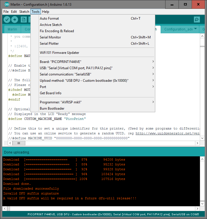
Upload from Arduino IDE
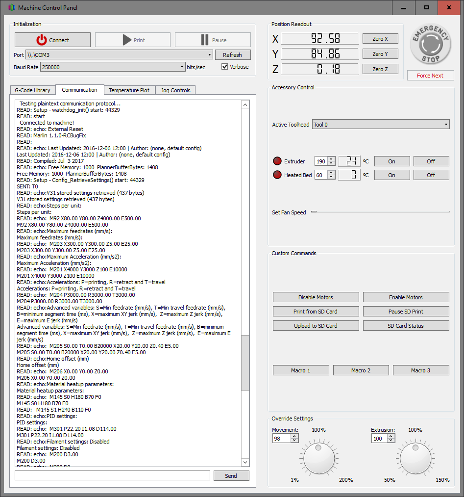
Serial comms via USB working
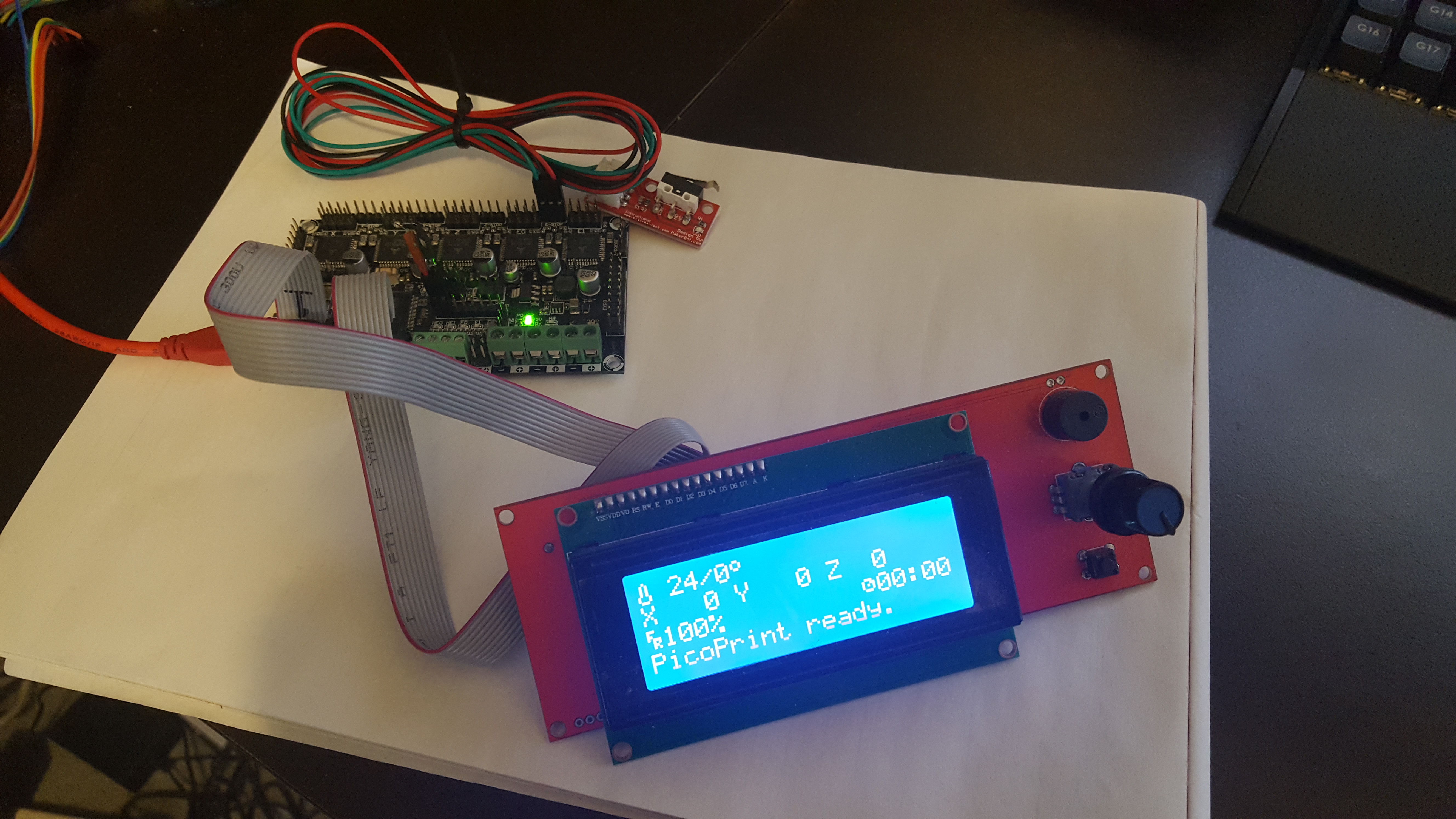
Board working with LCD and thermistor
I still have a lot to do before everything is working nicely and neatly, but if anyone else is trying to follow a similar path I’d be happy to provide any info I can.
I need to check the newer one based on STM32GENERIC, but as far as we dont hack Marlin much we should be able to port it to multiple MCUs and keep it updated.
I started with the port to the libmaple core and have a few things running already. That once has normally an advantage in speed and code size over the HAL based one, but in return it’s more difficult to adapt core from one MCU to another, although there are F3 and F4 versions that are very functional. Things like spi, timers, gpio, usb, usarts, work in all of them.
I’ll be happy to help with that HAL too.
I used the LPC fork to start with since someone said that fork is fairly up to date and the LPC HAL is functional.
About the DFU bootloader, that would be a nice adition for the F4 boards. Most people around here use stlinks and jlinks since the bootloader we use for the F1s has not been ported to other series.
I don’t know if that’s all your code or borrowed, but if it’s yours it would be great if you give it a free license and can be used by everyone, and possibly make it compatible with as many MCUs as possible, and add compatibility with the F1 bootloader so a single set of tools work for uploading, but that’s a whole other subject.
What board are you using in those pictures, is that a custom one?
About the LCD, I was planning to not even test text screens, and go directly for nice color TFT since we have plenty of display drivers working with the F1, and take advantage of the cpu resources, but that’s down the list after steppers, thermistors, temp… are working.
EDIT:
Just had a quick look at the HAL in this repo:
https://github.com/Aus3D/Marlin/tree/32 … /HAL_STM32
Are you using software SPI? I dont see the HAL SPI functions, neither the arduino standar ones.
[victor_pv – Mon Jul 03, 2017 6:11 am] –
Hey Chriss, I’m the same one that posted in github about porting to STM32 and you shared your repo. I opened this thread here to keep track of my progress.
Ah, I thought so but wasn’t sure! I’m glad to see the progress you’ve been making, I think it’s good that people are working on this – I’m looking forward to printers running on an STM32 becoming more commonplace.
[victor_pv – Mon Jul 03, 2017 6:11 am] –
I don’t know if that’s all your code or borrowed, but if it’s yours it would be great if you give it a free license and can be used by everyone, and possibly make it compatible with as many MCUs as possible, and add compatibility with the F1 bootloader so a single set of tools work for uploading, but that’s a whole other subject.
The bootloader I put together is 90% from one of ST’s example projects on how to implement a DFU interface, with the other 10% of stuff just being basic housekeeping code I wrote. I’m not sure what ST’s license is like, but as far as I’m concerned anyone is free to do whatever they want with it. I’d love to see it become a more generic bootloader for STM32 chips that currently aren’t covered by the old Maple bootloader. The main thing it’s missing at the moment is the board needs to be manually reset for the DFU-upload to take place, I had some intent to add an automatic-reset into the USB-CDC stuff in the STM32Generic core, but haven’t played with that yet.
[victor_pv – Mon Jul 03, 2017 6:11 am] –
What board are you using in those pictures, is that a custom one?
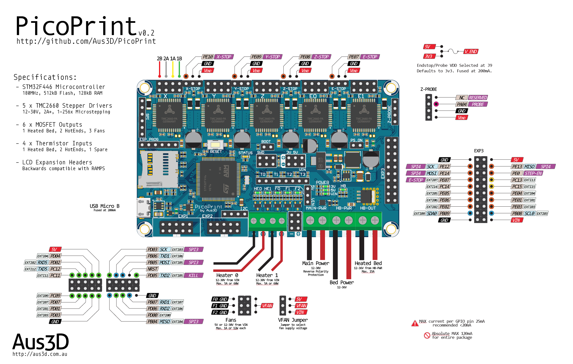
Yeah, it’s a custom board. I’ve been developing an STM32 printer control board since late last year (in stops and starts), and I’m using the current prototypes to test my Marlin work. I plan to offer them for sale at some point, once we have STM32 stuff nicely integrated with mainline Marlin.
I keep going back-and-forth on what should and shouldn’t be included in the board design, so at the moment I’d say while it’s well tested it’s still an early prototype in that everything is still subject to change. Back when I first did the current batch of prototype boards I made the below pinout image, for my own reference and for some practice – this gives some details on the board I’m using:
[victor_pv – Mon Jul 03, 2017 6:11 am] –
About the LCD, I was planning to not even test text screens, and go directly for nice color TFT since we have plenty of display drivers working with the F1, and take advantage of the cpu resources…
I agree, it would be good to see proper TFT displays in use now that we have the processing power. Generally, one of my goals is to have the best possible ‘backwards-compatibility’ with the existing hardware people are used to, so I really want to get common character and graphic displays that people already have working. One common complaint people have with 8-bit boards is that they can’t run a delta and a graphic (as in, monochrome LCD) display at the same time with good performance – I think it would be a good practical demo to show such a setup is now easily handled.
On the topic of TFT graphical interfaces, I’m in two minds as to the best way forward there. We do have the power onboard to handle that side of things with these 32-bit chips, but I kind of like the approach taken with the PanelDue where the display and interface is handled by a separate microcontroller, that then communicates with the control board via UART and standard G-Code.
An advantage there is that the UART + power connection can be any distance people might want on a printer, whereas an SPI or parallel interface to a TFT from the control board would have to be fairly short – so people would have to mount their display wherever the control board is.
Another advantage is that it means there’s no extra code in the printer firmware to handle the display, just G-Code parsing – so eventually you could have a display compatible with a range of control boards and firmwares.
Lastly, you can probably squeeze better performance out of a microcontroller dedicated to display/interface activities – I’d rather have an 80MHz MPU dedicated to the display than try juggling responsive display and real-time step generation on a 180MHz. Of course it’s definitely possible, I’m just speaking as to what I think would be easier – and with microcontrollers as cheap as they are, often it’s easier to share the work around.
That said, as you’ve pointed out with existing libraries and examples it would be relatively easy to get a graphical display up and running, and there are a lot of advantages to that approach too.
[victor_pv – Mon Jul 03, 2017 6:11 am] –
Are you using software SPI? I dont see the HAL SPI functions, neither the arduino standar ones.
Some of the code in the HAL_STM32 folder is unmodified from the Due HAL (where it was copied from), and I think that includes the SPI stuff. AFAIK those files include methods for a bit-banged SPI and the Due’s hardware SPI. That’s currently unused, the STM32Generic core is handling the SPI side of things on the F4 – so far I’m only using hardware SPI to talk to the stepper drivers, but that seems to be working well. I could probably delete those SPI files from the HAL folder, but I haven’t done so yet.
That’s part of why I like using the Arduino core approach, it removes the need to setup SPI, I2C, UART etc within the Marlin HAL. Though I’ve only tested with the one STM32Generic ‘board’ so far, that being for the F446VE, it’s very likely that the Marlin HAL would work with other ‘boards’ with minimal changes – so it may be possible eventually to get any STM32 supported by the STM32Generic core running Marlin.
[chrissb – Mon Jul 03, 2017 8:53 am] –
The bootloader I put together is 90% from one of ST’s example projects on how to implement a DFU interface, with the other 10% of stuff just being basic housekeeping code I wrote. I’m not sure what ST’s license is like, but as far as I’m concerned anyone is free to do whatever they want with it. I’d love to see it become a more generic bootloader for STM32 chips that currently aren’t covered by the old Maple bootloader. The main thing it’s missing at the moment is the board needs to be manually reset for the DFU-upload to take place, I had some intent to add an automatic-reset into the USB-CDC stuff in the STM32Generic core, but haven’t played with that yet.
I think we should copy the method that libmaple uses to reset the board. That would provide some compatibility at least for doing the reset, even if a different DFU uploader needs to be used.
We also provide for USB re-enumeration without using a extra pin and circuit, so it works in generic boards that do not have the circuit.
[chrissb – Mon Jul 03, 2017 8:53 am] –
Yeah, it’s a custom board. I’ve been developing an STM32 printer control board since late last year (in stops and starts), and I’m using the current prototypes to test my Marlin work. I plan to offer them for sale at some point, once we have STM32 stuff nicely integrated with mainline Marlin.I keep going back-and-forth on what should and shouldn’t be included in the board design, so at the moment I’d say while it’s well tested it’s still an early prototype in that everything is still subject to change. Back when I first did the current batch of prototype boards I made the below pinout image, for my own reference and for some practice – this gives some details on the board I’m using:
Nice, looks like a very clean design. I would only mention that since the steppers are onboard, you may want to add a sixth one on board, althougth no I see you already planned the expansion on E1.
You may also want to move the reset button somewhere more to the edge of the board, although that’s hopefully not needed often.
[chrissb – Mon Jul 03, 2017 8:53 am] –
I agree, it would be good to see proper TFT displays in use now that we have the processing power. Generally, one of my goals is to have the best possible ‘backwards-compatibility’ with the existing hardware people are used to, so I really want to get common character and graphic displays that people already have working. One common complaint people have with 8-bit boards is that they can’t run a delta and a graphic (as in, monochrome LCD) display at the same time with good performance – I think it would be a good practical demo to show such a setup is now easily handled.On the topic of TFT graphical interfaces, I’m in two minds as to the best way forward there. We do have the power onboard to handle that side of things with these 32-bit chips, but I kind of like the approach taken with the PanelDue where the display and interface is handled by a separate microcontroller, that then communicates with the control board via UART and standard G-Code.
An advantage there is that the UART + power connection can be any distance people might want on a printer, whereas an SPI or parallel interface to a TFT from the control board would have to be fairly short – so people would have to mount their display wherever the control board is.
Another advantage is that it means there’s no extra code in the printer firmware to handle the display, just G-Code parsing – so eventually you could have a display compatible with a range of control boards and firmwares.
Lastly, you can probably squeeze better performance out of a microcontroller dedicated to display/interface activities – I’d rather have an 80MHz MPU dedicated to the display than try juggling responsive display and real-time step generation on a 180MHz. Of course it’s definitely possible, I’m just speaking as to what I think would be easier – and with microcontrollers as cheap as they are, often it’s easier to share the work around.
That said, as you’ve pointed out with existing libraries and examples it would be relatively easy to get a graphical display up and running, and there are a lot of advantages to that approach too.
I think you are right on that, but as far as USART displays using gcode I think the support already there should work out of the box. I need to see how is that configured, I hope Marlin allows to use one serial for host communication and another one for the display.
Did you have to modify the u8glib or the LCD lib to support that display? what about level shifters?
[chrissb – Mon Jul 03, 2017 8:53 am] –
Some of the code in the HAL_STM32 folder is unmodified from the Due HAL (where it was copied from), and I think that includes the SPI stuff. AFAIK those files include methods for a bit-banged SPI and the Due’s hardware SPI. That’s currently unused, the STM32Generic core is handling the SPI side of things on the F4 – so far I’m only using hardware SPI to talk to the stepper drivers, but that seems to be working well. I could probably delete those SPI files from the HAL folder, but I haven’t done so yet.
I have that part rewritten to use our core, and should be compatible with the STM32Generic one too, so once I upload my code just borrow that SPI file. That file is used for the sdcard transfer.
Which SPI port are you using for the steppers?
I wrote that file to use SPI (so spi1) since that’s what Arduino does, but could be modified to use another port if that’s the one you use for the steppers.
I am really surprised to not have seen any open source board using STM32s. They are cheap for the amount of features they have. Even with STM effort on Marlin4ST, the only boards using it commercially that I have found are closed source.
[victor_pv – Mon Jul 03, 2017 2:59 pm] –[chrissb – Mon Jul 03, 2017 8:53 am] –
The bootloader I put together is 90% from one of ST’s example projects on how to implement a DFU interface, with the other 10% of stuff just being basic housekeeping code I wrote. I’m not sure what ST’s license is like, but as far as I’m concerned anyone is free to do whatever they want with it. I’d love to see it become a more generic bootloader for STM32 chips that currently aren’t covered by the old Maple bootloader. The main thing it’s missing at the moment is the board needs to be manually reset for the DFU-upload to take place, I had some intent to add an automatic-reset into the USB-CDC stuff in the STM32Generic core, but haven’t played with that yet.I think we should copy the method that libmaple uses to reset the board. That would provide some compatibility at least for doing the reset, even if a different DFU uploader needs to be used.
There is CDC reset, same as libmaple.
[danieleff – Mon Jul 03, 2017 3:11 pm] –[victor_pv – Mon Jul 03, 2017 2:59 pm] –[chrissb – Mon Jul 03, 2017 8:53 am] –
The bootloader I put together is 90% from one of ST’s example projects on how to implement a DFU interface, with the other 10% of stuff just being basic housekeeping code I wrote. I’m not sure what ST’s license is like, but as far as I’m concerned anyone is free to do whatever they want with it. I’d love to see it become a more generic bootloader for STM32 chips that currently aren’t covered by the old Maple bootloader. The main thing it’s missing at the moment is the board needs to be manually reset for the DFU-upload to take place, I had some intent to add an automatic-reset into the USB-CDC stuff in the STM32Generic core, but haven’t played with that yet.I think we should copy the method that libmaple uses to reset the board. That would provide some compatibility at least for doing the reset, even if a different DFU uploader needs to be used.
There is CDC reset, same as libmaple.
Is there a board reset triggered if 1EAF is received as in libmaple? I believe that’s the part Chriss is talking about having to be manually reset.
If not, could we add that to the core?
I was having a look at the steppers and the board config file. I see the steppers support an SPI interface, and they can even be daisy chained one to another, so they shift out data to the next stepper as long as CS is kept low, but can also be managed independently with their own CS line each.
I understand you are using SPI only for configuration but not to set steps and dir is that right?
I need to double check, but I believe Marlin4ST uses the SPI port for everything, which saves a ton of pins, and allows for fast SPI transmissions.
Anyway, something to look at down the road, but I wanted to comment on that in case you are already using it in your board and I didn’t see.
[victor_pv – Mon Jul 03, 2017 3:55 pm] –[danieleff – Mon Jul 03, 2017 3:11 pm] –[victor_pv – Mon Jul 03, 2017 2:59 pm] –I think we should copy the method that libmaple uses to reset the board. That would provide some compatibility at least for doing the reset, even if a different DFU uploader needs to be used.
There is CDC reset, same as libmaple.
Is there a board reset triggered if 1EAF is received as in libmaple? I believe that’s the part Chriss is talking about having to be manually reset.
If not, could we add that to the core?
[victor_pv – Mon Jul 03, 2017 4:11 pm] –
@ChrissI was having a look at the steppers and the board config file. I see the steppers support an SPI interface, and they can even be daisy chained one to another, so they shift out data to the next stepper as long as CS is kept low, but can also be managed independently with their own CS line each.
I understand you are using SPI only for configuration but not to set steps and dir is that right?
I need to double check, but I believe Marlin4ST uses the SPI port for everything, which saves a ton of pins, and allows for fast SPI transmissions.Anyway, something to look at down the road, but I wanted to comment on that in case you are already using it in your board and I didn’t see.
i did a little read up on polou’s A4988 modules which are the RAMPS modules
https://www.pololu.com/product/1182
http://www.allegromicro.com/~/media/Fil … sheet.ashx
it apparently doesn’t have a SPI style /CS pin, the only control pin /ENABLE is to turn off/on the mosfets (active low)
that would seem to say that an ‘SPI’ style connect may not really be feasible. either way the main pins are basically STEP and DIR
it would be good to have /ENABLE there as well, but i’m guessing that we can group all the /ENABLE into a single stm32 gpio control pin.
i.e. all or none, all FETs on or all FETs off across multiple motors, that could help save a couple of pins but not really a lot of it
p.s. read a little more on the web, it seemed it isn’t a good practice to keep the FETS enabled, it simply heat up the motor & the driver chip esp when currents is large when the motor is not moving. in that case keeping the enable lines separate is possibly a good thing as the motors do not always move together
I’m not sure how much control there is in the TMC ones, but the STM L6470, the one STM used in the EVAL board, allows full control with SPI. You can even send a command to tell the driver to what position you want to move the motor, and the stepper will take care of the acceleration, move, and deceleration.
Seems like a pretty good feature compared to having to send a number of pulses and having to keep the count in the MCU.
Have a look at the datasheet http://www.st.com/content/ccc/resource/ … 255075.pdf
Anyway I was checking STM code in Marlin4st, and not even them use the SPI port for that in that driver ![]() they only use it to configure the driver, but then send pulses and direction in 2 pins as the other drivers.
they only use it to configure the driver, but then send pulses and direction in 2 pins as the other drivers.
One thing that they do differently than normal Marlin code is that they use hardware timers in PWM mode to send the pulses. I’m not sure how much cpu time that saves given that they service an interrupt for every pulse.
Marlin instead uses a single timer loop to manage all the steppers, by toggling the step pin up and down directly. the timer doesn’t toggle any pin, but is just used to call that function periodically.
About the enable pin, I think many boards just keep them all enabled all the time. Any board using a 64pin MCU should have enough, the Maple mini is definitely constrained in the number of pins, although as far as the code fits, it can be enough for a basic printer.
1/128 microstepping and SPI interface
it would really make the 3d printing run extremely smooth
a4988 and drv8825 has only 16 and 32 microsteps respectively
http://reprap.org/wiki/A4988_vs_DRV8825 … ver_Boards
but i’d guess it is also part of the reason why ST’s reference 3d printer board comes at a premium in costs at least
actually it didn’t matter too much as the different boards e.g. RAMPS have its own board includes. this would allow those who has the better stepper drivers to use a board.h file and stepper driver codes that use less pins. and those who use RAMPS would need to use a board with lots of gpio pins, but they go with different board.h files and stepper drivers codes
[danieleff – Sat Jul 08, 2017 4:38 am] –
Why is it not a fork, but a new repo?
Hmmm, there isn’t any specific reason. Once the Marlin main devs merge their HAL layer to the Main, this will be submitted as just a new folder in their HAL subfolder. At that point it will not exist as either branch of fork, just part of the master Marlin.
In the meanwhile I just uploaded it in case any wants to check it out, so not much planning on which way I was uploading it.
He printed successfully a couple of days ago with a Malyan M200 board, and I printed with custom board I made for these test.
I updated the first post to reflect the progress.
It’s now in the official Marlin 2.0 bugfix branch, but I have to upload and submit the very latest changes I have been doing in my local copy, and xC0000005 may have submit some too, but now Marlin is functional in STM32F1
I used an stm32f103vet. I forgot whats in the M200 board, but whatever MCU verson it has, it can fit Marlin too.
https://hobbyking.com/de_de/main-board- … -m100.html
I see the printer could get some firmware improvements and the Marlin firmware could be a good fit. During my investigations I found this thread and that someone is already working on this port. My plan was to order a spare board and start experimenting with this. I may be able to help on this project.
I’m working with an global team to develop STM32 based flight controllers since quite a while and have been deeply involved in the firmware development for this flight controllers:
https://www.alienflightng.com/
I’m actively developing for BetaFlight and iNav, but was also was working on Harakiri, BaseFlight and CleanFlight in the past. I’m using Eclipse with the GNU ARM tool chain for this development. I used Arduino in the 8bit version in the past for the MultiWii with ATMega chips where I also did some work years ago.
I haven’t done much in the code size because I was testing with another closed source board, a Chitu3d, and just finished with that a few days ago, and was able to print with Marlin.
xC00005 has been working on the Malyan, and he has successfully printed too. If that board is similar to the Malyan, all you need to do at the current time is map what pins are used for each function (step, dir and enable, for each stepper, thermistor inputs etc) and you should be able to print with it.
I believe xC00005 has last been working on the sanity check code, that checks your configuration in marlin (like 2 functions don’t use the same pin, etc).
We still need to work on the LCD part.
Currently we are working off my branch of the code, that’s almost up to the official 2.0 branch.
There is a lot of changes going on in the official branch for the LPC, and may take a while to get a PR merged, so I thought it would be easier to work on the STM32 in my HAL as I can merge more often, and then send PR to the official every once in a while.
also the official seems to break a bit more often due to so many changes going on, while the one in my fork is stable working now for us.
It’s here:
https://github.com/victorpv/Marlin/tree/bugfix-2.0.x
Nice open sourse “duino” compatible projects are available which enable closed loop control so many motion problems would be fixed. Then one idea is to have control part for 3-4 steppers in one bluepill which would communicate with another one running Marlin, while on stepper side having motor driver and position sensor in case closed loop is used…
mechaduino:
http://tropical-labs.com/index.php/mechaduino
https://github.com/jcchurch13/Mechaduino-Hardware
https://github.com/jcchurch13/Mechaduino-Firmware
Similar to above nano_stepper:
http://misfittech.net
https://github.com/Misfittech/nano_stepper
simpler and cheaper ustepperr, interesting side of this project that you may use cheap Polulu A4988 driver as is:
http://www.ustepper.com/index/what-is-ustepper/
https://github.com/uStepper/uStepper
Regarding current project status: I like where you’re going with using the Pololu style stepper driver modules.
I’m just wondering, when using the DIR/STEP driver interface, why not put them behind SN74HCT595 (or 74AHCT595) shift register(s)? With one of these, the board should be able to drive 4 steppers from just 3 pins:
1. Feed 8 bits of data via DATA/CLOCK pins
2. pulse LATCH to “light up” the DIR/STEP ports we set in step 1
Since the shift register can operate at 100MHz that shouldn’t be a bottle neck?
I think there has to be a timing delay of 19ns between CLOCK and subsequent LATCH (19ns ~ 52MHz).
Add a second shift register three pins can control 8 steppers (or better: 5 steppers, 3 hot {ends, beds}) [at half speed compared to the single register].
The ST datasheet only mentions the toggle frequency of 18 MHz for APB2 (but they don’t [seem to] do DMA). To solve that, maybe they can be “talked” to via one of the two SPIs (which have DMA; just use CLK+MOSI to send 3 bytes for three registers, put LATCH on another pin and pulse it after DMA is done).
If more “slow” pins are required (fan control, microstepping, hot bed), those could also be added by just adding a bunch shift registers in a chain; e.g. 2 for microstepping control of 5 steppers (15 bits, 3 per polulu board) and a third for 8 channels hot bed/FAN/LED control,… Since that’s all stuff which is probably not updated every few ms, these could go to any three pins.
Might be off there, but just my 2c – and might be better/easier than keeping two MCUs in sync ![]()
[Late night edit]: I totally forgot about the endstops, but you can check these with a shift register, too. Needs three pins and an ISR on one of them: one switch between each register pin and the stm32 input pin; pull all pins on the register high; if at least one switch closes, the ISR needs to test all switches for the one which was triggered; while that happens, no stepping should occur. If the switch is kept active, the endstop state has to be polled after each step cycle.
To sum up:
– fast: SPI/3 pins (18MHz, DMA)
– slow: 3 pins
– endstops: 3 pins
– 8 bit Shift registers: 2 + 3 + 1 = 6 (mouser: 0.215$ @ 100pcs as SO16 74AHCT595D)
The remaining pins can be used for LCD/SD/…, assuming those are suited for that purpose.
Of course there is no need to go “all in” on shifting stuff around, maybe it’s enough to use one or two of these.
Similar alternative: MCP23S17T (10MHz SPI; SSOP-28 and smaller) or MCP23017 (1.7MHz I2C, SPDIP-28 and smaller) 16 bit I/O Expanders (<=1$ @ 100pcs).
Pins on these are I/O and can be configured to trigger one of two interrupts (neat for endstops).
See https://www.mouser.com/ds/2/268/20001952C-1129816.pdf for their common datasheet.
[end of late night edit]
i’m trying to compile the code on a Open103Z (STM32F103ZET) very close of 103RET but i’ve an issue during compilation :
sketch\src\HAL\HAL_STM32F1\persistent_store_impl.cpp: In function 'bool HAL::PersistentStore::access_start()':
sketch\src\HAL\HAL_STM32F1\persistent_store_impl.cpp:56:20: error: 'class CardReader' has no member named 'read'
bytes_read = card.read (HAL_STM32F1_eeprom_content, HAL_STM32F1_EEPROM_SIZE);
^
sketch\src\HAL\HAL_STM32F1\persistent_store_impl.cpp: In function 'bool HAL::PersistentStore::access_finish()':
sketch\src\HAL\HAL_STM32F1\persistent_store_impl.cpp:70:23: error: 'class CardReader' has no member named 'write'
bytes_written = card.write (HAL_STM32F1_eeprom_content, HAL_STM32F1_EEPROM_SIZE);
^
exit status 1
Erreur de compilation pour la carte Generic STM32F103Z series
Now I can connect to my stm32 via pronterface
I’m preparing a test board now :
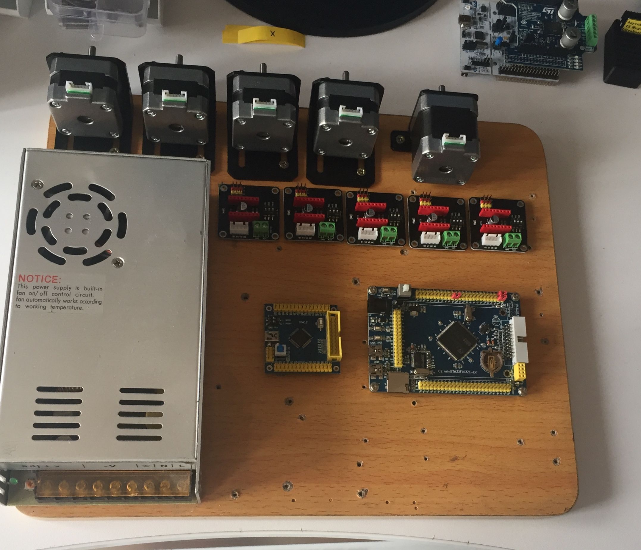
I’m going to try to test with L6470 too
Thanks so much Victor for your HAL, it’s going to have a great success because it’s the most promising platform for Marlin 2.0. A stm32 chip is cheaper and powerful than an AVR. we could expect to use the blue pill for minimal configuration. This is amazing!
I’m glad that you work it working. I have tested it successfully with VET and ZET mcus.
[youprint – Tue Feb 06, 2018 7:38 pm] –
There is a small pb with spi but I think you will find the solution quickly when you will have time for that. I mixed your repo and the official repo to get it work because on your repo there is a pb with HAL timers. I spend 3 days but it’s compiling now. Tomorrow i’m Going to test motors and limit switches. If everything is ok I will try it on my test printer. I hope to get SPI work because I really like spi drivers like L6470.
I have used an SPI port with the SDcard without any issue. All SPI ports should work, unless some other part of marlin is broken by those updates.
https://github.com/MarlinFirmware/Marlin/pull/9019
I have a RepRap Discount LCD and a 12864 too so I think I.m going to try it but it’s coming from Arduino so I have to check if I need to level some signals.
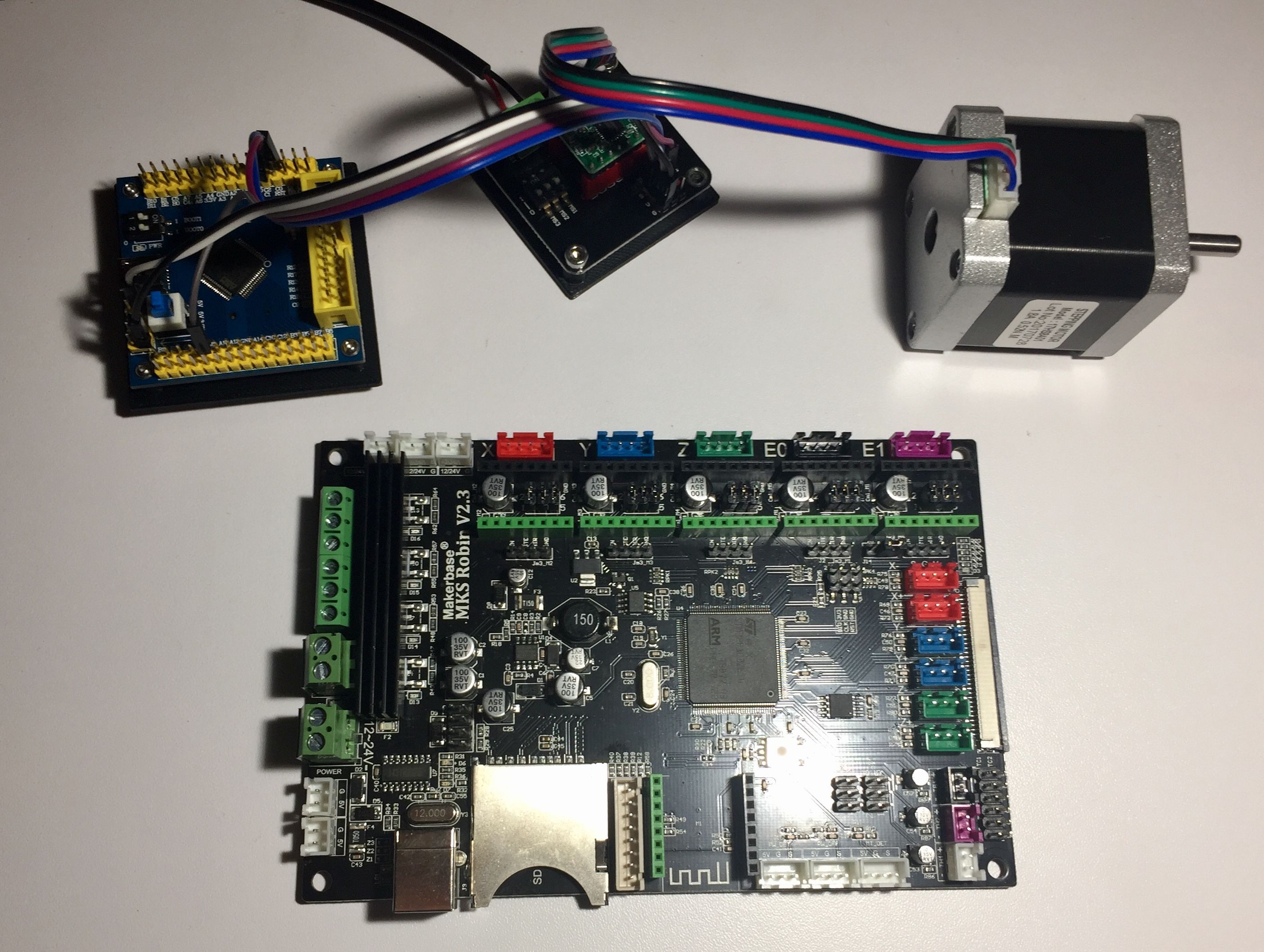
Working on a MKS Robin with an STM32F103ZET6 to install the Arduino Bootloader. Apparently the chip is locked, I can’t unlock it with a Jlink V8 in SWD so I have to try with a Jlink V9 or with a BMP.
I saw a HAL F7 now which it’s working, only a F4 HAL is missing and we will have all the STM32 family of products.
I’m going to start on a project with LinuxCNC, since it can support 3Dprinter. My objective is to use a Raspberry pi in master with an STM32Fxx in slave mode to allow rpi access to fast IO of the STM chip via SPI. It already been done with an FPGA (Spartan 6 via SPI) but it could be cheaper with a Blue Pill and the driver for FPGA could be a really good start. All i need is a good HAL for the STM, so I need to learn more… ![]()
https://github.com/MarlinFirmware/Marli … gfix-2.0.x
^^^ this is a branch, marlin 1.x is here
https://github.com/MarlinFirmware/Marlin
the facebook group is here
https://www.facebook.com/groups/marlin32bit/
stm32 is apparently getting more attention

