~Straw
I think what you are suggesting is to make a ramps board that connects to a STM32 board, e.g. put a socket in the middle of the RAMPs board and plug a STM32 board into that socket rather than plug the RAMPS into a Mega 2560
I’m not sure how may pins you need and whether the Maple mini or most generic STM32F103C boards would have enough pins for this
You may need to use a small STM32F103VET board instead, as it would definitely have enough pins.
The other consideration is of course the voltage levels, as I’m not sure if the POLO stepper drivers can be controlled by 3.3V (you’d need to check)
Something ramps style was also my first thought, with the maple board plugged on the top side.
There shouldnt be any problem with pinout, as the ramps basically just uses ~24 pins. there could be a problem when using lcd, sd card or something else.
For me, this seems as an bit easier project than the ultimate dev board *cough* *cough*
with an vet6 board this could end up like something really crazy. but also an idea. guess i add one in my next order ^^
Well, i’ll take a look at the weekend. but i have to check if atleast marlin is directly compatible with the maple/stm32.
~straw
The other consideration is of course the voltage levels, as I’m not sure if the POLO stepper drivers can be controlled by 3.3V (you’d need to check)
-5 Stepper Driver (15 Pins)
-6 Buttons for Min. & Max. (6 Pins)
-3 Thermistors (3 Pins)
-2 Hotend (2 Pins)
-3 Fans, 2 for Hotend + 1 for Driver (3 Pins)
-1 Heatbed (1 Pin)
That way I basically end up with no Pin left, fits perfectly ![]() .
.
Working on a schematic now.
~Straw
This would of course mean going to some larger STM32 board, such as e.g. this one, as already proposed by Roger. But given that you will be putting a lot of time and effort into this, it might be worth while.
~Straw
~Straw
There are news? I am particularly interested in this project for some time that I try to document me.
I am listening.
Drk
Im going to start it next week, as im on vacation currently and ive got like 2 weeks time then, plenty i hope. thinking about putting th chip directly on the board instead of using a dev board, its like 7$ cheaper (but its maype bit harder for beginners to solder) maybe it will be a option to choos from, either onboard chip or devboard.
but ill post more updates in the following week, have to see bit more of italy ATM
straw
Away again till next week
~Straw
Away again till next week
~Straw
Please excuse the crudeness of it all, I don’t get much free time these days.
https://github.com/simonantonio/Ithika/ … -Rough.pdf


Great work @Strawberrymaker !!!!!!
To start, we need a simple card. This is essential for us to start writing a firmware and test it on a 3D printer.
So, I believe that we need this:
a) 4 Motor Driver (X, Y, Z, E)
b) 6 EndStop
c) 2 Thermistors (Hot-End, bed)
d) 2 Power outputs PWM (Hot-End, bed)
e) 2 UART
f) 1 (SPI More CS)
g) 1 EEPROM (Microchip 24LC1025 or smaller )
Regard
drk
lcd might be interesting as from its pin labelling its wired on the fsmc, also not figured where all the devices are connected to address wise
stephen
Nice Idea, something simpler. Would be bit hard with a C8T6, but should be easily with something like a ret6. Wouldnt it be better to move the EEPROM part to the IC itself? Havent played with the STM32duino EEPROM Library yet, saving some pennies, making it more approchable, or something like these cheap atmel eeproms.
but well, i will take a look at it
There is also SPI Flash libraries, I’m currently using this one : https://github.com/LowPowerLab/SPIFlash
I’ve even submitted a PR for Cypress FRAM support (you can see it there in github), but it is not merged yet …
Nice Idea, something simpler. Would be bit hard with a C8T6, but should be easily with something like a ret6. Wouldnt it be better to move the EEPROM part to the IC itself? Havent played with the STM32duino EEPROM Library yet, saving some pennies, making it more approchable, or something like these cheap atmel eeproms.
but well, i will take a look at it
~Straw
~Straw
Looks good to me ![]() 16cents per unit for a 20 pcs order. And look at the cure, little BGA package available, like 0.8×0.7mm
16cents per unit for a 20 pcs order. And look at the cure, little BGA package available, like 0.8×0.7mm ![]()
~Straw
Looks good to me ![]() 16cents per unit for a 20 pcs order. And look at the cure, little BGA package available, like 0.8×0.7mm
16cents per unit for a 20 pcs order. And look at the cure, little BGA package available, like 0.8×0.7mm ![]()
~Straw
~Straw
I just took the old schematic and removed some Thermistor Inputs, PWM Outputs and Drivers. In terms of MCU, I think the STM32F103RCT6 would be good. Same Flash size as the mega, and just 1.30$ per unit in a bulk of 5 compared to the ret6m with double of flash, which costs 3$ per unit in a bulk of 5.
I have to recap everything i got so far in parts, but i hope it wont go over 25€ (excluding pcb).
~Straw
EDIT: Did the Math, still missing thing like Header Pins and the Car Fuse holders (which are hard to find in china as it seems). With a 24V Version, its about 20€, normal 12V would be 19€ Sound good to me, but there could still be changes Made to the Voltage Regulators, which costs, with circuitry, def. about 4€
I’ll buy a board. The cost, I think it is right at this stage of development.
drk
I was thinking two things. Kicad uses to develop the Board?
We organize a GitHub repository for shared development?
I think this is important.
Drk
Im going to push the repo when i’m back home. Kicad looks really NEAT, but can i simply import the eagle schematic and the custom libraries or do i have to redo them.
Marlin is still a goal. I think i pulled the mosfet design from the ramps-FD and added a diode. (Note to me: dont forget to add their names later on.
To the naming.guess that Name has to be dropped. Adding nucleo and discovery support is simply too hard, the Pins would take too much space IMO, putting the MCU on the board seems to be a more easier way. Another idea would be to put a VET6 or ZET6 PN a basic Version board and designing a connector, similar to the radds one, and make an external Adapter with more stepper drivers and PWM outputs, but that would hinder the develolment of the board. First goal is to make the development board and make the Firmware running.
About F4, not quite sure about pin-compability between F1 and F4 ( Function wise). And F4 isnt really up-to-date, so that will take a while
~Straw
Straw, Look what I’ve found at this Link : http://www.geeetech.com/forum/viewtopic … 13&t=17173
I tried to look for this card on the web but could not find any information. For now is a mystery.
Drk
I prefer Kicad. It is an excellent CAD and is completely open.
I have learned to use it by following this guide video: LINK
Eagle is a commercial product, the free version has limitations and projects are not convertible.
drk
so basically making a custom stm32 board which plugs in into a pcb (the 3d printer driver).
not quite sure if i like that idea, as it will increase the cost (extra pcb, headers) and wont benefit much than just exchanging the chip if it dies. and there isnt that much that can happen to it. Im going to make sure that the cooling pad for the Mosfets is big enough, reverse polarity protection, protecting mosfet with diode. nothing can really go wrong there. and still this board has to be manufactured for cheap.
@Drakelive
Gonna try it today, pushing the repo (currently eagle) soon. that page you posted it not available for me atm.
~Straw
~Straw
~Straw
just asking, for making the porting easier: Would it be harder to re-wire I2C Stuff to other I2C Ports or should i get that one onto I2C1. Atleast for the current plan, its on I2C2. Just asking
~Straw
On ESP gitter, there was on guy who didn’t any things about PCB, and he start learning doing is first design using KiCad.
The next day, he was showing us his first gerbers. Although there was glitch in them, mainly due to his unexperience, not because of Kicad.
So, just take few hours to try it out, and ask help if needed …
Coming back to the fuses, Im starting to doubt the Use of them. Yeah, its really good to have one if something fails and not that everything blows up, or that the MosFets will get damaged, but then looking at the available RepRap Boards, many of them are even missing Fuses, just a handfull of boards use resettable fuses and maybe 3-5 use car fuses or normal glass fuses. The Car Fuse idea was a big too much i guess, glass/ceramic fuses seem to be a better way. Comes out cheaper. Something like this, for example. Well, a thought. Would be great to hear some comments onto that lil’ thought ![]() Wish me luck with KiCad ^^
Wish me luck with KiCad ^^
~Straw
strawberrymaker wrote:
Seems like the board you referred to is something custom from geetech for their printer.
couldnt find anything either.
But I already rewirered it to the first one, so dont bother with that.
Gonna push the PDF in a few seconds.
A question about kicad: you add the component in the schematic first and when the schematic is finished you add the footprint to it, rifht?
~Straw
Coming back to the fuses, Im starting to doubt the Use of them. … but then looking at the available RepRap Boards, many of them are even missing Fuses
A question about kicad: you add the component in the schematic first and when the schematic is finished you add the footprint to it, rifht?
~Straw
OK, gonna add the car Fuse on the final board, you convinced me
But to complete a list of boards without fuse: melzi, (sanguluno or something), smoothiboard also dont has one (if i remember correctly). So we can do it better
But i was reffering to the available boards, not the share of the boards.
No suprise that the eagle files didnt looked nice. Already pushed a PDF of the schematic, maybe check that one out. I’ll try to get the schematic copied into kicad, but i need some time to get into it and source the libraries needed. Hope im finishing it this Weekend.
My personal deadline is still next Week. Hope im managing it ![]()
But i think even on the final Version, the 5V Buck converter is OP, would be better to find a 3.3V Buck, AS the 5V line isnt used except for some pinouts like UART or SPI
Gotta go back to work, back in 4H
~Straw
To the Git Repo and the two trees: I initially started with the 3 Color, which seems kinda odd, as 3 Color setups are REALLY rare (maybe diamond hotend) and then split it into a 1 Extruder Board which im currently working on (to get development faster going), so that one is number 1 priority. I just pushed the 3 Extruder Schematic just for reference, that one isnt really important now ^^.
Yeah that C Board should be fine, but still, development on that board is currently on hold.
ATM im really not quite sure if making it into a “real” Ramps-style board is the way to go. Increased bulk, less complexity of the pcb, higher price, saving the board if the uC dies, struggle of adding the female headers and routing everything aroung it.
A thing im worried about is that there are more than one f103V board out there, which may make people”upset” that their wont fit on it. with ramps and ramps-fd, the pro is that it follows a board which cant be altered really, but the isnt a real guideline to f103v boards.
But well, for the dev-board a soldered one should be fine. guess adding or planning it later on shouldnt be hard.
Your buck converters: is the bigger one fixed voltage? looks also appealing
~Straw
Sorry but I I have to understand. You want to cut the 5v? But such voltage levels, you would work SPI? 5v or 3.3v ?
I wish I could manage a chip Max6675 for thermocouple K for the extruder. All my printers use thermocouples.They are easier to install and are much more reliable. Modules that use (Aliexpress) are fed to 5V.
The connector for End-Stop are all 5V tolerant? I think this is a good choice.
drk
on all the separate card modules i have, there is a 3v3 regulator on board and interface circuitry.
cheaper ones, resistors and a chip on the slightly more pricey ones.
now stm32 pins whilst i believe they are mostly 5v capable, i’m still not convinced you can run the card modules off just 3v3.
on the board i’m thinking to use, it has a card interface, i just have to find out where it’s mapped to … …
stephen
If you talk to Chinese DEMO-BOARD I bought this ( 10 euro ) :
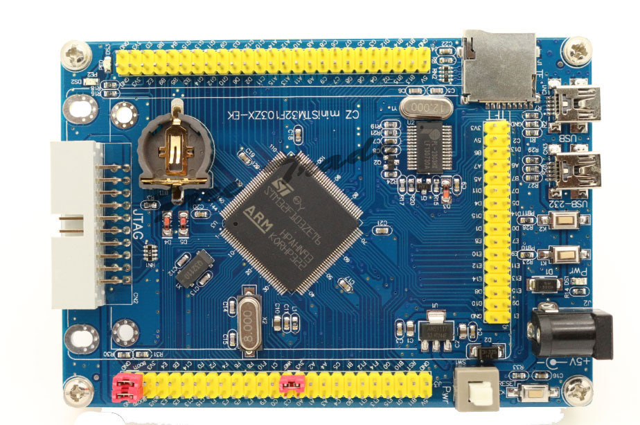
- CZminiSTM32.jpg (232.48 KiB) Viewed 879 times
@Drake I think i didnt thought about 5V tolerance on the endstops, guess i can swap around between the driver chips and the endstops, as they are currently on some ADC Pins, which arent 5V tolerant. Havent thought about thermocouples. Ok, 5V shouldnt be dropped. maybe adding a cheap ams1117 5V should do the job.
@zmemw16 SD Cards operate at 3.3V Voltage and Logic level. But my Idea was to take a SDramps module port instead, as SD Card slots are really bad to hand solder IMO.
But back again, i still dont think using a extra board for the Microcontroller is a good idea. Makes it just complicated and more expensive (for someone who doesnt has the right board lying around).
To KiCad: Is there any tool to highlight wires which are connected together, like the SHOW tool in eagle? and is there any way to move a part WITH its wires connected? Thanks. Will push the KiCad update when im finished with the motor drivers.
~Straw
be warned – make sure the 2.1mm plug you use is supplying 5v – mine was 12v. oops.
actually my dead one might be the non lcd version, i have at least 2 other variants; with / without lcd & with / without sd card.
there might be even more with empty smd pads for spi flash, eeprom etc.
anyway, i tend to buy more than one as well.
a long time ago in part of my work life, when doing design, build and production of mil-spec hardware, second and third level component sourcing was common, usually for 25yrs as standard. the prices reflected that as well.
stephen
If you talk to Chinese DEMO-BOARD
.. but ULis not possible, it exeeds the limit ![]()
well, here are other examples of minimum system development boards:
Here or here
I just mean, there isnt any “standard” for it as it is for the arduino. I see that the RAMPS was made as a modular board because many people already had Megas so there wouldnt be any additional cost, but looking at something like these stm32 boards, not really that many people have them (except for the folks in this forum maybe). And looking at this becomming something like a proper device usable for a consumer, this would just bring up more cost:
If this will support a “modular” mcu you will have to buy the board (which is already 10€) and the female header will also be maybe ~2€. Results in 12€ BOM cost for the MCU.
If it will be a soldered mcu, the vct6 costs just <2€ in a bulk of 10 or 3€ if you buy everything by yourself (btw im planning on selling kits anyway), caps cost maybe ~10 cents in total (if you round it up) and the crystal im planning to use (btw. a resonator, so i dont have to hassle about the right caps, although this is kinda small, can be swapped out for something else). costs like 30 cents per part. USB port also maybe 10 cents MAX aaand thats it. like 3,50€ (or even just 2€ if its in a bulk, just seeing the first price as a worst case scenario).
And thats a difference of more than 8€. Im trying to make this as affordable as possible. the ramps is doing to great because its affordable compared to other solutions. the board alone costs like 5€ from china, 10€ if you get it in a kit with the arduino. A Melzi board(you see that really often in chinese acrylic prusa i3’s) costs ~30€. Thats mostly the key. Keeping the total cost as low as possible, so it appeals to a bigger market.
And really whats the point of having a removable mcu? If you burn a mosfet, changing the mcu wont change anything.
And actually telling me to use a autorouter is 1. horrible and 2. didnt helped me with the struggle of getting used to kicad in the schematic editor at all. just sayin’.
@zmemw16 currently the goal is to get a board finished with one extruder to start porting the Marlin firmware and while that is happening, trying to get stuff going with LCD’s and stuff. I could maybe change the Microcontroller on the dev. version to the Vet6, which would bring in more pins and we could start working the pins out. The SDramps module uses, as any other SD Card SPI, so that will be used. I already labeled the SPI Pins on the schematic, but didnt worked the pinout out.
~Straw
~Straw
EDIT:

The Idea is to use individual modules for the axis, extruders and other things. Using something like dual row angled pinheaders they will be connected. Having one “mainboard” which houses the F103V uC (or even maybe F103Z), USB Connector, Power In, SD Card reader and all the pinout (For the Module and for everything else). Problems will rise with the headers max. current (male pinheader have ~2-3A, the female ones only ~1A), which may be ok for the stepper drivers(3Axis only pull max.6A), but something like a Heatbed would require something around 2×16 Pinheader, which is quite big for a module only holding a mosfet (maybe 8 parts in total). And the modules will also have screw holes, so they can be screwed down onto a holding plate.
This would be a something unique idea to solve the problem with making it modular, while still having something of a “norm” board and making it still cheaper (although not that cheap, have to look up the prices of the headers). and it would still be expandable. And those modules should pretty much fit in a bigger amount onto a single 10x10cm board, making the module’s pcbs pretty cheap. If this seems to be a good idea which is worthwhile checking out, i think starting a new thread wouldnt be a bad idea.
Maybe drop a thought about it ![]()
~Straw
And I finally found a datasheet for afuse holder. Link to Datasheet. So Im trying to make a footprint for it.
After using KiCad for a while im getting slowly used to it. But kinda bothers me that i cant search fast for the right footprint. A field where i can enter a text (like *SOT23*) and it shows me every footprint with that in the name is something that really should be implemented. But thats just one thing. I already made a new repo called ReST32 (Reprap ST32 controller. But havent commited anything to it.
Got the basic schematic of the mainboard finished, Heatbed module is also almost finished (just missing that fuse holder).
~Straw
I think of starting a new Thread, to clear things bit more, so we actually start with that project and that people can follow the discussion more easily.
Currently in the repo is the start of the mainboard schematic (Just the MCU ATM) aswell as the Heatbed Module Schematic and the fitting parts on the pcb (which I will work on tomorrow).
~Straw
~Straw
But i dont think i used every of these libs, thats crazy.
Well, that autoroute doesnt seem to be that great, let it be the trace width.
Sorry for that, didnt knew they are necessary ^^
~Straw
~Straw
But somehow im not really happy with it, it seems still too big, with around 4.5cm * 3cm. That fuse really takes up a whole lot of space. But the other modules shouldnt get that big then.
Could you try to open it? I really fucked up with the libraries, included them now, but i really dont know how to manage that one really. Any suggestions about that? Thanks ^^
~Straw
But I cannot download, no clone, no zip.. will try tomorrow evening…
Libs..oh yeah, I’m fucked up too. Quite heavily.
I told one of them guys something about “frustration levels” ![]()
At least I installed all actual footprint libs locally.
But I’m still stressed with with my self constructed footprints, they are not listed in CvPCB.
But it seems I’m not alone, I found many cries for help and vulgary comments.
At the moment CvPCB is absolutely buggy.
So no other way than try & error for finding a driveable road, track, path, trace…
Guess that is a fault on githubs side that you cant download it.
About CvPCB: I found a flowchart in KiCad’s docs  . I think i’ll try that one out. Hope that it is actually better in terms of libs handling and faster. Really crazy how long CvPCB takes to load. Ok, ~30 seconds isnt much, but takes much time if you need to swap something out fast.
I still want to make something like a small mosfet driver module for things like fans etc but im having a really hard time finding something suitable with ~3A and VGS higher than 24V.
Wondering if they will add a function to automaticaly generate the netlist and load it into pcbnew. Yeah i know, its just a small step, but its a small thing (which i loved about eagle).
~Straw
It seems like the first “commercial” STM32 based printer boards are out (even in china) —> scroll down to “new control system”:
http://www.aliexpress.com/item/Geeetech … 68672.html
Only question: is it a RET or VET?
<edit> ok, this was maybe not the first board, here is a ZET based on (expensive): http://www.aliexpress.com/item/3D-Print … 61811.html
But we got something open-source, and easily fixable ![]()
Well, still got some work to do, aim is to get that thing with modules out for a lower cost than the radds.
~Straw
It seems like the first “commercial” STM32 based printer boards are out (even in china) —> scroll down to “new control system”:
http://www.aliexpress.com/item/Geeetech … 68672.html
Only question: is it a RET or VET?
<edit> ok, this was maybe not the first board, here is a ZET based on (expensive): http://www.aliexpress.com/item/3D-Print … 61811.html
that’s a bit of a diesel, add-ons needed to really run, improving power & efficiency ![]()
Looks pretty neat, but im personally not a fan of soldered stepper driver ![]()
Kinda pushes me to finish that PCB faster ![]()
~Straw
including a higher power stepper motor drive board.
Ok, think I nailed all the modules there. Heatbed, heater, stepper and additional High Power PWM Output (For Fans and such).
Sizes: Heatbed: 4,8cm x 3cm
Heater: 3,4cm x 2,9cm
Pololu Holder: 3,5cm x 2,6cm
Additional: 3,9cm x 2cm
Now comes the working on the mainboard schematic, and then the real pain: the pcb x) .
Well, will be hard to make a 4 extruder board with the size of dirtypcb’s 10x10cm. Think 2 should be enough (and most common) anyway.
~Straw
EDIT: Just noticed that is kinda questionable if a pololu holder is really necessary.
I already pushed a new update. Just some small things:
-copied the pololu holder for 3 Axis and 2 Extruders.
-Changed MCU To VET6
-Added USB Connector and ESD Protection
-added 5V Regulator (3.3V still missing though).
~Straw
Here’s a link for a PDF of the pinout
Maybe someone could report if i made the LCD Parallel Pinout right (8 bits and 3 control pins, right?)
Sooo…only need to add the actual pins on the board and as mentioned, add the pin names to them. Then start designing the board (and checking everything).
~Straw
For info : http://www.st.com/web/en/press/p3781
![]()
![]()
![]()
finally they understood …. better late than never!
So now, all ST libraries are freely usable?
drk
@bianchifan already took a look at it?
Back to the controller : I swapped out the additional board to use a uln2803 npn transistor array. a really beast for its size (and price). thought that would be pretty neat (and would save up much space).
Critism is welcome ![]()
~Straw
istr 02/03/04; input stages are 02 no idea, 03 is ttl(?), 04 is cmos
i didn’t realise, i’d thought it was only the output voltage capability and now have a number of spares:-)
stephen
To which manufacturer are you referring? Could you maybe drop a datasheet?
~Straw
EDIT: found the [url0http://de.aliexpress.com/item/New-original-ULN2803ADWR-ULN2803ADW-ULN2803-TI-genuine-LSGDZ/32468995665.html]TI ones, around 30 cents a pop[/url], but a different package
nowadays my primary data sheet site is farnell, also google, when i had money farnell got a lot of it. cpc is their slightly better priced site, but not necessarily the parts range of farnell.
then i discovered aliexpress, ebay and amazon, so now it’ve still no money ![]()
stephen
dip has higher total current compared with the smd version.
quite sizeable difference/ratio iirc
srp
~STraw
~Straw
stephen
Also on the Github Page

Yeah, its currently a bit messy, will clean that one later on.
But im having a problem with that BOM Generator tool in eeschema. Trying the standard Plugins, getting IO Error (invalid argument). Would be great if someone could help me with that one ^^
I have to look that i finish it AFAP, because my exam period starts in like 2 weeks.
@bianchifan ok, i think i figured out how to fix the problem with the missing libs and packages. guess i’ll have to export the used packages from third party libs and import them into the rest32 lib. So the only thing you’ll need to do is including that one lib.
@madias thx for the mention on the reprap forum, think i’ll post something there too (at latest when its finished)
~Straw
And i def. have to revisite all pinheaders, guess there can be some space saved.

But i will go to sleep now, getting late here, bye
~Straw
<a href="http://puu.sh/nhGkW/591a4f0182.png" class="postlink">PNG</a> or <a href="http://puu.sh/nhGxU/7a8bab8c95.png" class="postlink">PDF</a><br>
~Straw
Edited it.
Managed to finish the main PCB over the night. man, it took some time!. Some 3D Pictures:


Other images:
Heatbed Module Top
Heatbed Module Bottom
Heater Module Top
Heater Module Bottom
Stepper Module Top
Stepper Module Bottom
Additional Top
Additional Bottom
PDF’s and PNG’s are in the Repo ![]()
I will change some bits in the readme and then check if everything is right in the schematic.
Would be great if someone could check some pins on the F103V if their functions are really working:
PA5-PA7 | PB1 | PC6-PC7: PWM
PC4, PC5, PB0 : ADC
It should be ok (according to the datasheet), but better safe than sorry.
@RogerClark hope its OK that i used the stm32duino logo. if not, let me know.
~Straw
~Straw
EDIT: Added
I am getting the following missing libraries message
The following libraries were not found:
dp_devices
ok-74logic
ok-con-generic
ok-diodes
ok-generic
ok-ic-analog
ok-ic-atmel
ok-ic-com
ok-ic-memory
ok-ic-power
ok-ic-special
ok-ic-stm32
ok-jacks
ok-opto
ok-power
ok-relay
ok-switches
ok-transformers
ok-transistors
pololu_a4988
Dp_devices: the kicad library of dangerous prototypes
OK…: they are all Form github (okirsch was the user)
Pololu: the poloklu stepper driver library.
I will find a way to fix that problem. Hopefully its enough to just remove Them since i didnt used them all.
~Straw
On the PCB, some components like the STM32, some capacitors, the switch and others, are not appeared on the 3D preview.
I had to re-load the 3D shapes Footprint Properties -> Add 3D Shape
Congratulations Matthias (strawberrymaker), Very nice work!
And thanks for the compliment ^^.
~Straw


Only thing missing would be a small heatsink area for the 5V regulator.
~Straw
I stopped my KiCAD projects for the moment, too much trouble with cvpcb, I do not get the trick.
But i’ve learned, I’m not alone
Next I was struggling with an USB scope, at least I returned it and orderered a new one some minutes ago.
I DL’ded rep last night and had only a quick view just even.
All schematics can be opened but they are still full of errors, i.e. missing the known libs Ok-, dp- …
PCB can be opened and viewed in 3D, Gerbers can be plöotted.
When opening the main project only mainboard is visible, I cannot branch to the modules. (I have probs with hierarchical projects , too)
I’m wondering about ULN.., in 2016 I would use Mosfets only, IRLML2502 or IRF7413 /IRF7311-Dual for ex.
The stepper module PCB shows 2 lines outside.
Thanks
I finally managed to delete all of these libs which i installed locally and it should be clean now.
Yesterday I tried using the hirarchical project tool, but it seems to just allow one pcb design. Also tried to just make a new empty project and moved every module folder into it, but then some schematics would “vanish” and kicad wouldnt recognize them. So yeah, seems like an easier attempt to just open a new project every time, for now.
Stepper Module, these Lines should be the ground planes, forgot to move them to the board edge, but that shouldnt make any difference.
About the ULN, you are right. I just used the ULN because it was the only multi npn array i knew (and had my hands on) and which is easy to solder (nice dip package). But since the PWM Channels moved from 8 to 4, a different package would work much better. Thanks for the suggestion of the 2502, will work on a second design now ![]()
Im currently having problems with my Git Software (Gitkraken), it wont push into the repo since the latest update yesterday.
~Straw
And also added the Additional Board based on the IRLML2502. Also have to work on a lil adapter for a simple 204/12864 lcd, nothing that fancy. (Still looking to drive a ili9341 with 8bit parallel). I will take a last look at the schematic and then finish up the BOMs and put some things into my shopping cart
The Main PCB is going to be 2 ounce copper instead of 1, simply because of the power traces (would have to be like 14mm wide). going to cost a bit more, but that doesnt seem to be that bad. Rest ist going to be 1ounce. Have to look onto how to combine multiple gerber boards into one, so i could use a 10x10cm pcb for the modules.
~Straw
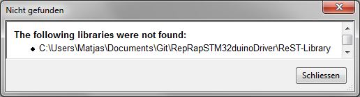
- notFound.jpg (13.15 KiB) Viewed 870 times
~Straw
I have seen the progress on the project. These are remarkable. ![]()
How much work is there? From what I see it seems that the work is almost finished.
After the design how you want to proceed?
I want a board to begin developing on Marlin.
Drk
Yeah, its almost finished. I will take a last look at the pcbs this week, then order everything this weekend (PCBs and parts) in a low quantity (currently looking at 10 pcbs max.) and test it first out, then send out kits (or even prebuilt) to everyone interested here. Think that everything should be here around eastern time. then starting to port marlin, and well, who knows what will come next ![]() .
.
Straw
~Straw
EDIT: I will look that i finish the combined pcb panel and then look for alternatives with pcb shopper.


For PCB service, elecrow seems to be pretty good in quality and they dont seem to have problems with panelized layouts
~Straw
They have some examples on their PCB store page
I intend to try them, but I have no specific project at the moment.
Please feedback if you do find a PCB maker who will make a panel like your picture.

Also ordered the parts yesterday, pretty hyped to see everything come together.
~Straw
I am not sure what you mean about them being taken down.
I presume you mean they are closing their business.
Can you post a link, to this information, as I will need to find another manufacturer ![]()
Edit.
Found it
and i wanst sure about dangerousprototypes because they have an option “panelized boards” which doesnt give me any real option.
One problem with dirtypcb is that they dont do V groove, so you have to use panelised.
But I never tried to see if panelised works for them, as my designs are in eagle and I only have the normal commercial version that only allows up to 10cmx10cm
So i would not be able to create a large panelised or V groove board.
I now have KiCad installed, but its still quicker for me to use Eagle, as I know how to use it, and I have a good set of libraries for the components I use all the time.
However in the longer term, when I have time, I will try to move my boards to KiCad and do big panelised / V groove multi board layouts.
I did manage to get a simple board design done quite quickly in KiCad.
The confusing this is the way packages are not linked to symbols like they are in Eagle
But as I have some designs in Eagle which I’m just modifying a bit to make variants, its much quicker for me to stay with Eagle for those boards.
If I have time and I’m doing a totally new board, I will hopefully do it in KiCad
The confusing this is the way packages are not linked to symbols like they are in Eagle
It’s not possible to make subcircuits or repeated circuits in the layout editor AND(!) PCB editor together. This could be really annoying.
Ok, for sure, you can repeat the circuit on the PCB but you’ll lost the control (and power) in the layout view.
It’s not possible to make subcircuits or repeated circuits in the layout editor AND(!) PCB editor together. This could be really annoying.
Ok, for sure, you can repeat the circuit on the PCB but you’ll lost the control (and power) in the layout view.
~Straw
Until recently there has not been a lot of OSX support. I was having to build source from the nightlys. If you think library management on linux is horrible. On OSX it is even worse as a lot of stuff is installed in areas that the user normally does not have access to. Then others think it should be in the /usr tree which Apple really does not like apps writing too. I think the latest versions now use the /Library folder. But there are two of these one system and one in the ~/ home directory.
KiCad really does not like making self contained projects that reside in the documents directory. I think this has improved in the last year. The last time I looked most of the online docs were about 18 months out of date or so from the current code base.
The confusing this is the way packages are not linked to symbols like they are in Eagle
They really Tried not to make an image from the board
~Straw
They really Tried not to make an image from the board ![]()
~Straw
~Straw
Yes. I eventually found that, but I’m not sure what I have done is correct.
I think I will download you KiCad design and look at those things.
BTW. I also had issues with non connected pins on an opto isolator (4N35), as I normally don’t connect pin 6 (Base of the opto transistor), but to stop the error I connected the base to Gnd via 100k, as I think this would not have much difference from it floating
However, there must be some way to allow some pins to not be connected, even if the symbol specifies that they have to be connected.
@RogerClark
there is a blue x in the right tool bar, thats for unconnected Pins.
Thanks
strawberrymaker wrote:I already placed my order on elecrow.com and they accepted it, its already in production ^^. 
I need a TOP3 footprint, and think I need to make it myself
Thanks
~Straw
madworm’s BLOG <- excellent source for some KiCAD hints
elecrow thread on Mikrocontroller.net with lotta stuff (Nutzen)
~Straw
~Straw
Does this mean I should continue to use DirtyPCB’s, especially as I don’t need cutouts at the moment ?


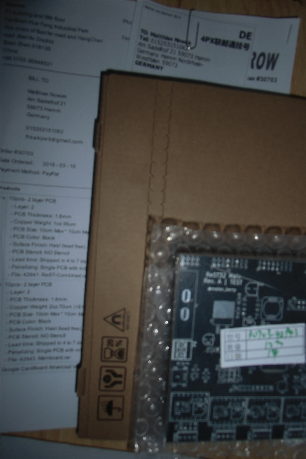
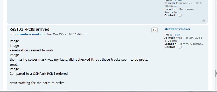
Panelization seemed to work.

the missing solder mask was my fault, didnt checked it. but these tracks seem to be pretty small.

Compared to a OSHPark PCB i ordered
Now: Waiting for the parts to arrive
~Straw
Image..?
…
Image??
- Zwischenablage01.jpg (36.24 KiB) Viewed 649 times
~Straw
Perhaps you have a browser settings issue.
My guess is the browser settings… or a browser limitation with inline images.
Ray
Perhaps we should start a KiCad and PCB thread?
Ive finally finished producing my first board using KiCad, and its been relatively painless
Well, there have been problems, but when I first started to use Eagle, I think I had the same, steep, learning curve.
I sent the files to DirtyPCBs yesterday, and they accepted them after I manually fixed a problem with the edge-cuts file extension ( they want .GML not .GM1)
It was going to be a STM32 board, but I bottled out in the end, and I will use a Maple Mini attached to the board via a 5 wire ribbon cable.
The board has both high voltage, high current, 240V 20A, and low voltage devices on it, (optocouples and a Hall effect current sensor; so has been a bit of a challenging design, trying to keep the HT and LT sections apart but not make the board to big.
I’ve used air gap slots in several places, so it will be interesting to see how they are handled by DirtyPCBs. ( Note, I used DirtyPCBs old system, as the new one has only just come back online following bug fixes)
I will let you all know how the boards look when they come back, and if they are OK, I will move to version 2 which will have the STM32 on the board.
Would you share some pictures of the gerbers ?
Ciao !
Would you share some pictures of the gerbers ?
Ciao !
As its my first, rather simple board, done with KiCad, I don’t think its that good. But its OK as a prototype board.
Its not a commercial board, its ultimately for my sister.
I initially wanted it to be all surface mount, but it was impractical to use high voltage SMD capacitors. Theoretically you can get them, even on AliExpress, but I didnt trust that the ones on AliExpress were really 400v working.
Also, I couldnt easily find specs on the 1W SMD resistors, so I ended up using through hole on those as well. So as I had to do all the HT side as through hole, I decided, at least to start with that the LT side may as well be through hole as well.
I had to make footprints for the connectors and the power triac, as I couldn’t find existing KiCad footprints for the BTA41, and not for the Dimple 40A screw terminal. (nor for the ACS712-20, or for a SMD bridge I was going to use, and for SMD versions of the optos (which again I didnt end up using)
I also initially routed all the tracks on the top of the board, which was a bit of a mistake for the power through hole stuff, so I had to reroute with most tracks on the bottom.
I then has issues with stitching the copper pour zones for the ACS712, as its SMD, but I wanted to use both sides of the board, as there is 20A going to those tiny SMD pads (yes, it really is rated at 20A though 2 SMD pads !!!)
Probably overkill
Anyway, I’m sure you’ll see problems with it, but I’ve uploaded a screengrab, and I guess its probably not to late to catch problems as its not gone to the board house yet ![]()
PS. I think I’ve already uploaded it at least 5 times, (the first 2 were because it didnt accept the edge cuts file), the next 3 or 4 where when I say errors e.g. annotation text on the wrong layer, and problems with the stitching vias etc etc
Note. There are air gap slots in the middle of the board and under the optos, (in case you wondered what those polygons where…)
Oh. And there is no ground plane, as it most of the board is high voltage and I have to maximize insulation distance, hence large areas of the board with no copper on at all.
Also note some of the HT tracks, are larger than they need to be, but as long as I preserve creepage distance (if possible 2.5mm or more), then I may as well go for large tracks even if its not carrying much steady current – only pulse / switch-on current of perhaps 1A to the BTA41-600 triac
Argghh, In hindsight I can swap pins 4 and 5 on the pin header, it doesnt make any different … and it would save a via….
But I’ll leave it for now.
Edit (again)
Any my other mistake.
The triac is not in the middle of the board. I should have probably made the board a bit wider, but I can’t be bothered now to change it.
Its really just a prototype.
Funny request
Are you overjoyed you did not ask for “gerbils” ???
Thanks for updates !
It seems to be really application specific pcb !
So, your first Kicad experience wasn’t to harmful ?
Keep us informed …
Ray ? I don’t understand your funny answer …
So I see if they accept it, and whether they can cope with the air gap lots etc.
The other thing that will be interesting if how KiCad copes with the zones that don’t have thermal relief.
I had to use “Solid” instead of thermal relief around the high current pins on the mains connectors and also on the triac, as it needs to handle a relatively large amount of current (20A) sustained, as it will run a electrical water heater.
So it will be interesting to see how this comes back, as I have a concern that selected Solid for the zone’s thermal relief setting may mean that the pads for the triac and power connectors may not get created correctly, and I’m likely to have to scrape off the solder resist.
I really hope the through plating doesnt get screwed up on the connectors, as it will be a pain to solder them on, especially for the neutral connectors which go to the SMD current sensor (ACS712)
But I will know in a few weeks just how screwed up the boards are…
KiCad didnt seem to default to “plotting”the solder mask.
So I didn’t send solder mask files to DirtyPCB’s ;-(
I think the board will still be usable, as there is only 1 smd component, but I’ll see what i get back, or whether they even make the board with those files missing.
i was expecting pictures of the boards’ top & bottom layouts as well
srp
wrath of khan was on the other night
and i’m not a seller from Venice either
srp
~Straw
I see now the gerber view looks different, now I also have those layers, but I didnt know what it was supposed to look like.
Ideally DirtyPCB’s should give a warning if some common layers are missing.
The boards should be usable even with the solder resist missing, except one SMD part may be hard to solder, but it has large pads, so should be OK.
Of course a solder mask layer can be easily forgotten since it looks like the solder pads layer, moving then as mentioned above, you will quickly see if it is there or not.
First of all, the good one: Almost everything has arrived ![]() Only waiting for the fuse holder and the angled connectors. Guess they will arrive next week.
Only waiting for the fuse holder and the angled connectors. Guess they will arrive next week.
Another one: IT WORKS ![]() Tried a fast and dirty blink test, and well, it blinks
Tried a fast and dirty blink test, and well, it blinks ![]() Im really glad it turned out to work. Maybe i will upload a small video of it.
Im really glad it turned out to work. Maybe i will upload a small video of it.
Ok, now some bad ones:
-The Resistors for the 3.3V Buck converter arent the best. Since i didnt paid any attention on how precise they are, i have to pay bit more so i can get them locally. seems like these 5% ones make a shift of about +150mV = 3.45V. So i will try to get them locally.
-As for now, it seems like every connection on the Mainboard is there, buut on the SD Card one ground reference is gone. It was in the gerber files, but seems like i didnt met their capabilities, so they simply removed it. because of that, the Power LED on the SD Module isnt working. The ground reference for the additional output module is also missing on 3 of the 4 outputs. But the Heater and Heatbed modules seem to be fine. tried them, and they work. The Ground reference of the sd card has also been removed. so its worthless, aswell as the additional module (unless you want to use some jumpers)
-The heater/heatbed LED is inversed. So i have to change their connection aswell.
-I totally forgot to add some 12V/5V/3V3 LEDs on the mainboard. So they have to be added.
-And for some reason the mounting holes on the mainboard are gone. either I didnt saved it or removed it because of a github pull. Could bet i posted a picture of them somewhere.
-Some of the silkscreening is not correct. As far as i have noticed: The Caps of the 5V regulator have to be the other way around. The 3V3 Diode has to be the other way around. Most of the LEDS also have wrong Silkscreening. Not sure how it happened with the leds. But the caps are most definatly because i still used normal ones in the schematic and then assigned a polarised cap footprint.
-And there arent any dots for IC alignment. That also has to be changed.
-and i forgot most of the better silkscreening. Things like Pin Names, Voltage Pinouts, Boot selection, Voltage selection, Driver Microstepping etc. isnt silkscreened. my fault.
—-
TL;DR: It works. but there are still some minor mistakes, which can, for the time being, fixed with two or three jumpers.
I will post some pictures as soon as the last parts have arrived.
~Straw
I don’t think you have many errors for a complex board.
Mistakes always happen, and we just have to learn by them.
My first simple board using KiCad, may be totally useless, as I didn’t export the solder mask
The issue with the missing track on the SD, highlights the issue with DRC in KiCad.
This is one good thing about Eagle, as companies like DirtyPCB, have made Eagle DCR files.
I really should have tried to use the Eagle DRC somehow with KiCad ( I will need to find a converter), but as my board was mainly Not SMD, i hoped I could just use the default KiCad DRC.
It sounds like you needed DRC settings from elecrow to avoid the problem with the missing track
yeah, and luckily, they arent really major problems. could have been worse , Imagine the buck converter AND the mcu to let off some magical, sparkly smoke
They have a really in depth spec list, but i might havent imported everything correctly into kicad. i can remember setting up some design rules and using the drc tool, but it seems like i didnt managed to add everything. And IIRC the DRC from eagle is far more customizable than the drc of kicad. Definatly too less options. Or maybe there are some hidden options which i havent found.
Another way of fixing it would be to reduce the seperation distance of the ground layer, but they would just reduce it anyway.
Soo, spacing things out a little bit? seems fair enough.
Oh, one more thing: the Heatbed smd pads are all still for 1206. Soldering a 0805 part into there wasnt really a problem, but it kinda looks out of place ![]()
Off for today
~Straw
repeat the above, get a couple of other people to do the same and you’ll all still miss one.
way too many QA reviews, design reviews, software reviews etc etc
stephen


For some reason, this seems to be too big. Another idea would be to make the modules stack on top of the mainboard, which would be really neat, but i would have to redo most of the stuff. so guess thats a task while working on the marlin port, i guess? ![]() And ive got to search for a smaller fuse holder, something for like a mini atc fuse instead of the regular one.
And ive got to search for a smaller fuse holder, something for like a mini atc fuse instead of the regular one.
As soon as the fuse holders are there, i would be ready to ship out some packs. So if anybody wants.
~Straw
Just build the modules as part if the main board.
If people dont want those features, they dont need build the sections of the board.
( This is common on many commercial boards. I often see boards where sections are empty of components)
Or.
If board area is an issue, you would need to stack another board completely over the top of the main board.
Personally, I find connectors are always a problem, on the edges of boards.
I fear that this board is too big. The external molules do not like and I occupy too much space.
The SD module may be removed and added the connectors to a display (display, encoders and SD)
http://reprap.org/wiki/RepRapDiscount_Smart_Controller
or
http://reprap.org/wiki/RepRapDiscount_F … Controller
Everything else, would better to make an expansion borad to be connected above (or below) in arduino style
drk
so yeah, there is going to be much rework in the pcbs, but still, they seem to be working for the marlin port.
I also took a small look into the due marlin code, and it mostly seems to be rework in fastio to use the low level stm32 stuff. but correct me on that one ![]() .
.
Drake, that was also the idea why there are two sets of connectors, but i dont think they are directly pin compatible with the reprap controller, especially because it uses a level converter onboard, which would mean to make a board which converts the 3V3 logic from the MCU to 5V logic or just directly a new lcd. Could also be interesting for full color lcds.
~Straw
I used this old abandoned project, but do not know if this is a start to watch:
https://github.com/MakerLabMe/Marlin_STM32
We consider that it is based on a prehistoric version of Marlin
On my RAMPS FD (for Arduino DUE), I use this converter :
Fuse things: I finally found the fuse holders on farnell. I tried to avoid farnell, digikey etc. because the shipping was too high, but i didnt know farnell has free shipping to germany. Guess i get some of them (and throw a pi3 in there, its 30€ only ^^ ).
For the board connection: Yeah, something like mini shields would be a good idea. Stacking the board vertically seems better than horizontally. Using male smd headers on the “shields” and normal through hole female headers on the mainboard.
i will also try to remake the mainboard, maybe get a different footprint oscillator on there. and definatly rework the 12V rail, looking for max. 5°C temperature rise on the traces.
~Straw
I am picking up work on Marlin/32 again, with a bit of luck it will make it into Marlin mainstream this time. I would quite like to include an STM32 board as one of the supported HAL targets.
So I was wondering how you are getting on with firmware, and maybe we can get an STM32 version into Marlin?
but because wurstnase stopped on marlin4due, it would maybe be better to take the current marlin rc4, take the changes from marlin4due and add the precompiler parts to the fastio file so it can be used for due and stm32 (or just stm32).
~straw

~Straw
unfortunately SMD headers, at least the 1 and 2 row ones i have/or seen are somewhat wider as the pins bend outward either for each side for 2 row and alternately for single row.
for the single row( servo?? triples), you can at least pack them slightly more densely as the middle pin will fit between the outer pads of the adjacent one.
stephen
But this layout wont work anyway, way too much trouble routing the lcd connector. So that is goingm to change.
Hardware wise there hasnt anything changed since the first RC, only the 3V supply is now much smaller, cheaper but not replacable and some much smaller Mini Car fuses. Also now a reverse polarity fuse for the 12V Lines. But i will have to add some resettable fuses for 5V and 3V3 later.
I will just dump some pictures of everything.
Mainboard


Heatbed Module


Heater Module


Stepper Module


Additional Output Module


Still gotta rework the SD Card and got to create an adapter to use the reprapdiscount lcds.
~Straw
Parts and PCB should be around 35€ maxed out .
But not sure how i will handle assembly. I already looked at some smd vacuums, making them ma
nually should do the job for now.
~Straw
This lil’ pause also helped me in terms of the tunnel view that i slowly got.
I think i will trash the whole idea with the extra modules. If i rethink the whole idea, to be able two swap them out if they break, i was a good thought, but with the extra protection added for the mosfet (flyback diode, reverse polarity diode, all nicely fused, heatsink for the mosfet although it wouldnt be really necessary) i dont think it will ever happen that you have to swap the module out. And it kinda adds up bulk to the whole controller, making it taller than it has to be.
On another note: I also dumped the screw terminals for the stepper driver, because 90% of the stepper motors used in 3d printers have simple connectors on the and just a few of the china kits happen to have screw terminals on their controller, while the majority has connectors. Plus saving space.
I tried to make the whole board F4 compatible, but it seems rather hard because they differ in terms of pinout (if i have checked it correctly). If i find some time i might try it out again.
And i would like to try to control the microstepping settings digitally via an IO expander (MCP23017). Was just a crazy idea i had ![]()
~Straw
I tried to make the whole board F4 compatible, but it seems rather hard because they differ in terms of pinout (if i have checked it correctly). If i find some time i might try it out again.
Is there any news regarding this project?
I believe that today is necessiario start directly with a nice F4. With all this computing power will be the basis of many projects for a long time. Not only in 3D printing.
We really need an IO expander (MCP23017)? Add it to the board is definitely easy and some firmware for 3D printers so that they can activate the microstepping.
@Straw Now that the exam period has passed (:-) coped well with the tests? ), And now you’re more free, what you plan to use for the realization of this card?
Greetings
drk
I already managed to check the pin diagram atleast on the F1, which worked, but i didnt finished my small F4 Test board but there shouldnt be a problem.
The whole design is F4 conpatible, so its just a matter of changing the jumper pads and the micro for it. But having the option of a f4 for it still seems important. Although its slower, its still the most supported mcu here and it would take a bit more work to get it working.
The IO expander is also in the design, seemed like a nice idea ![]()
Hmmm….realization of the boars. Good question. Using china to outsource the PCBs is a standard (because most pcb manufacturer in germany charge wayy too much). And for the first few it would be enough to use a stencil to paste the solder paste on it manually and pick and placing the parts manually seemd good. Maybe getting and oven and modifiyng it to use for soldering the pcbs is good.
Its not like there are 1000 smd parts that i would be worried for the solder paste to harden while i place the parts.
But atleast all pin headers have to be soldered by yourself, just so that exporting it and shipping cost is as low as possible.
For the future, i dont know what would come next ![]()
But for now: trying to finish the next design before holidays begin in 2 weeks, because then im gone for 3 weeks and if i get all the new Parts ordered before im gone, i can test them happily in 3 weeks without school ![]()
~Straw
~Straw
So, gonna sum it up what changed since the last board:
- Hardware Support for the F103 and F407 series. (not sure about other F4 Chips)
- Changed the Fuse holder to mini automotive fuses (saves muuch more space)
- Moved everything now ON the board. all of the parts are as safe as possible and protected really good. making extra modules for everything makes power delivery bit more complex + higher cost and things are getting high.
- Added some reverse polarity diodes, just in case.
- Smaller crystal for the MCU
- Now WITH screwholes, in spec for DIN 912 M3 screws.
- Changed the Thermistor count to 6, so you can have extra redundance in every heater and the heatbed.
- LEDs indicating the Power Rails.
- 5V and 3V are now generated with buck converters. Also fused.
- Now with an adapter to (theoratically) directly use a RepRapDiscount Full Graphic Display.
- But still an aditional SD Card adapter (not microSD)
- Actually relatively proper Silkscreening
- ESP-01 Socket. Bit more experimental, but there are actually Web Interfaces out for it.
Now i just have to gather everything together and get everything ordered tomorrow
~Stra
There also doesnt seem to be another small board with pin headers, except for the esp-12 lineup, but all of this GPIO isnt really needed. I only connected GPIO2 of the 01 to one of the pins of the STM32, so you could maybe add a special function if needed.
~Straw
Great work. I want a PCB. When you’re ready mail me privately. Do not forget me
Drk
~Straw
I started recently diving into 3d printers, I am building a delta. There are many 32-bit controllers that are showing right now.
I am not sure if you saw the eval kit from ST http://www.st.com/content/st_com/en/pro … 001v1.html which is based on STM32F401 micro controller. There is also a firmware for it Marlin4ST https://github.com/St3dPrinter/Marlin4ST, could be that is newer than Marlin_STM32.
Would your board work with Marlin4ST firmware? Maybe it is worth considering this during the PCB design phase.
I think it’s compatible with it, as it’s based on the stm32cube, and the board is also compatible with f4 mcus as well as the f1. but I don’t like the cube licensing and that would take the open source part bit away.
I’m rather aiming to port marlin4due and make it based on the stm32duino core, seems easy enough. And i think there is also a port of smoothieware for the stm32 out there.
BTW, the PCN design phase is over atm. Just waiting for the new pcbs to arrive. And if they work properly, I think I’m done for the first bit in terms of changing stuff in the board.
It’s already F1/F4 compatible, has nice automotive fuses, two outputs and 4 additional. Seems more than enough for its price point (<60€, but got to calculate the BOM cost again tomorrow)
Straw
strawberrymaker wrote: … I don’t like the cube licensing and that would take the open source part bit away.
werent part of the cubemx code under MCD-ST Liberty SW License (or something like that)? Or did they already changed them all to MIT (or others).
IIRC they used a license which forced you to only use the software for stm mcu’s only. guess they changed it since then.
~Straw
werent part of the cubemx code under MCD-ST Liberty SW License (or something like that)? Or did they already changed them all to MIT (or others).
IIRC they used a license which forced you to only use the software for stm mcu’s only. guess they changed it since then.
~Straw
But, I don’t know if it allows use on the GD32 etc, I think it probably does not allow use on non-stm32 devices.
Some things that went wrong:
Pads for the fuses are too small.
wrong footprint for the transistors in the LCD adapter.
But now: gamescom ![]()
I just saw this in the STM news letter
Yes, I know her. It was designed by an Italian company. This board was presented last year at Rome MakerFaire, unfortunately it is a project in hadware closed.
ST achieved its Board:
http://www.st.com/content/st_com/en/pro … 001v1.html
https://github.com/St3dPrinter/Marlin4ST
Drk
I just thought I’d post in case no one else had seen it
BTW. Andy has posted about another STM32F103 based 3D printer (but I think its also commercial / closed source)
I just completed the third rev test boards and they are on their way from OSHPark. Once I get a successful test board, I’ll be posting documentation and build out a roadmap. I’ve quite a few things planned, including a touch-screen menu and some form of wireless support.
Feel free to follow along at the GitHub repo: https://github.com/tetious/STMPS
I’m now Watching your repo
If you want you can also take a look at my work. https://github.com/berryelectronics/ReST32 maybe we both can learn something from each other.
Did you see this post
viewtopic.php?f=3&t=1223&start=60#p17407
I suggested Gary should PM you regarding your hardware designs
Did you see this post
viewtopic.php?f=3&t=1223&start=60#p17407
I suggested Gary should PM you regarding your hardware designs
I mean Grey
(possibly auto correction or possible brain fade)
There is another example of using a NUCLEO-F411RE board together with a CNC shield V3 and Teacup firmware at http://forums.reprap.org/read.php?181,698882, a post made by Wurstnase. Sources are posted at https://github.com/Traumflug/Teacup_Fir … 2f411-port
so ordering them now locally, thats like a 1€ for each of these.
but well, finally get to finish the pcb ![]()


I think i managed to find out all of the faults, so these are going to get fixed ASAP. But i think its time to work on the Marlin port, so thats going to take some time. In the next few days i will atleast try all of the features out (Mosfets, stepper motors, reading out temperature, etc.)
~Straw
check if the chip the chinese seller is actually the one you wanted.
because it seems like the 5V regulator wasnt really the one i ordered. ![]()
But luckily only that regulator blew and nothing else.
~Straw
Any Idea how to Populate STM32F103xx with any 3D printer Firmware. If NXP chip was used we can easily port smoothy ware. But its STM32………
is this worth a try/…………
https://github.com/Rejdok/STM32-Marlin-Port
http://www.st.com/en/evaluation-tools/s … 001v1.html
Source code:
https://github.com/St3dPrinter/Marlin4ST
I haven’t looked at it much, but saw it’s based in Marlin 1.1.0, so not too old.
Also it’s for an F4 MCU, but since it’s based on the HAL, shouldn’t be that hard to port to a different series.
And final comment, it’s probably not too hard to compare their code to the official 1.1.0 release to find out what changes they did, and bring them over to the latest 1.1.3 release.
I also believe the Marlin project has been trying to rewrite the code to have a HAL to use different MCUs (I think teensy and Due are their targets), so perhaps using the STM develeped code as a base to write a HAL for the F4 or even F1 series is possible.
thanks @victor_pv i might look into it if i find some time in the summer break and then we will see how it goes from there on
~Straw
http://reprap.org/wiki/Arduino_Mega_Pololu_Shield
https://www.ebay.com/sch/i.html?_odkw=r … d&_sacat=0
those boards are rather ‘cheap’ on ebay (but do note that for most of the boards the Pololu modules are sold separately.)
the RAMPS boards are also mainly 5v boards, hence, some care may be necessary interfacing them
after getting the RAMPS boards and connecting them up with stm32 f1 or f4 boards, i’d guess we could start trying to port marlin
http://marlinfw.org/
to stm32?
imho those stm32f407 (black) vet6 boards make good candidates for 3dprinter controllers, lots of gpio pins, lots of functionalities on stm32f4 168 mhz stm32f4 processor 192k+4k sram 512k flash hardware fpu, it would likely make a *very fast* 3d printer which could do all those path computations in *floating point* on the fly
http://www.stm32duino.com/viewtopic.php?f=39&t=1391
http://www.ebay.com/itm/STM32F4-Discove … Sw-CpYAiTn
The advantage on those is that I feel it would be easy to make a board that plugs either on top or under that without wasting much space.
I have been searching for the last few days for a good board with support for at least 3 extruders, and seem that the only one I kind of like is the rumba, but uses a avr.
There is a couple of commercial ones based on STM32, but with closed source (Mks Robin and geeetech gtm32).
Really wish someone would design the pcb to plug one of those F4 boards so we could then port the stm eval firmware to it, and then bring it up to the latest Marlin versions, which are adding already a HAL layer for the Due and the Teensy. I do not think DUE or Teensy are any better than an F407, and are definitely more expensive.
https://github.com/St3dPrinter/Marlin4ST
http://www.st.com/en/evaluation-tools/s … 001v1.html
^^ this is ST’s ‘own’ 3d printer board
somewhat pricy at $116
looking at the schematics they are using L6474 stepper drivers
http://www.st.com/content/ccc/resource/ … 043117.pdf
rather than pololu stepper modules that may make porting it to a ‘generic’ board based on RAMPS/Pololu troublesome
then there is this Marlin for STM32F1
https://github.com/MakerLabMe/Marlin_STM32
but it seemed that it has not been followed up since about 3years back
I even found someone posted in a forum saying they have been using that board with that fw successfully for a while.
I had a look at it, and the changes are not so big or so many. Among other things they changed the sdfat library to Elm-Chan’s one, which is the one ST includes in the HAL, but Greyman’s one works with our cores and is the one used in Marlin, so there is no need for changes in that part, we could revert them or keep Elm-Chan, not a big deal, but by adapting it to the Marlin official HAL way, it would allow to keep updating with the Marlin versions.
The board is definitely pricey though. Specially just for testing and getting the ball rolling.
Something in the style of RAMPS but to plug in one of the $10 boards should be much cheaper, and more flexible for future changes, or repairs in case something breaks.
I’m thinking on grabbing a RAMPS or one of these, can be used to test fw in an F4, and if I abandon the idea I can still use to extend the number of extruders in my current board:
https://www.aliexpress.com/item/New-cnc … 00094.html
But I’m not even sure I have time to to invest on this. Haven’t been able to even catch up with new posts in the forum for weeks now.
https://www.ebay.com/sch/i.html?_odkw=r … d&_sacat=0
among the considerations are the 3.3v to 5v interfacing, i’m not too sure how complicated it is going to be
http://reprap.org/wiki/Arduino_Mega_Pololu_Shield
Any volunteer for that?
http://www.reprap.org/wiki/RAMPS-FD
https://www.ebay.com/sch/i.html?_from=R … D&_sacat=0
which it seems provides 3.3v interfaces, however, the board cost quite a bit more on ebay
if it turns out the interfacing requirements are too involved i may get that instead
actually ST’s board is pretty good and if one wants to simply get started, it’s probably the goto board currently out there for stm32.
the thing i dislike about ST’s board though is that the stepper driver ICs seemed apparently soldered on board this may lead to troublesome maintenance issues should the stepper ICs say become damaged for some reason. while for RAMPS they are socketed which makes it easier to replace
[ag123 – Wed Jun 28, 2017 5:21 am] –
there is RAMPS-FD for arduino Due
http://www.reprap.org/wiki/RAMPS-FD
https://www.ebay.com/sch/i.html?_from=R … D&_sacat=0
which it seems provides 3.3v interfaces, however, the board cost quite a bit more on ebay
if it turns out the interfacing requirements are too involved i may get that instead
actually ST’s board is pretty good and if one wants to simply get started, it’s probably the goto board currently out there for stm32.
the thing i dislike about ST’s board though is that the stepper driver ICs seemed apparently soldered on board this may lead to troublesome maintenance issues should the stepper ICs say become damaged for some reason. while for RAMPS they are socketed which makes it easier to replace
RAMPS-FD is expensive, and is made exactly to fit a DUE, so it has all the headers for it (sides and bottom one). I dont think is a good option to use with STM32 boards, but the schematic could be to use as a base.
Anyway at the moment I found a port of Marlin for a nucleo 446. I think I will try to get that running in an F407 and see what happens, and just use one of the cnc v3 shields to test the steppers. That’s what some people has apparently done before.
If the code works, then if someone is willing to design a board we will have something to test with.
I went doing a search of a simple stm32 board with the bare minimum and small footprint, and if possible on 2 different series, and found these:
https://world.taobao.com/item/419425520 … =19#detail
https://world.taobao.com/item/523361737 … =19#detail
They seem about right for what’s needed. Small, all the pins out, no unneeded components on board, and on 2 series, F1 and F4. If Marlin can work with Daniel’s core, shouldn’t be difficult to design a board that those plug in, and avoid soldering a 100pin mcu in a custom board. I recently replaced an F1 with an F3 is a blue pill, and although doable, is a pain in the ass. I would rather pay $10 to get the MCU soldered and just solder a simple 2.54 header.
Anyway all that is speculation, first let’s see if the code runs.
[ag123 – Wed Jun 28, 2017 5:21 am] –
there is RAMPS-FD for arduino Due
which it seems provides 3.3v interfaces
You can use any normal RAMPS, you have to change the FETs only, they do cost a few cents ![]()
And you may change some capacitors so you can drive 24V motors for more fun…
How to modify a standard RAMPS 1.4 to work with Arduino Due?
I’m still waiting for RAMPS 1.4 board to arrive from China but as far as I can tell the only changes required are changing fets to IRLB3034’s and somehow swapping the voltage pin to 3.3v on nucleo board.
I received a ramps last week and need to the test it with a re-arm board I got for beta testing Marlin on 32bits.
At the same time I’ll start testing my libmaple HAL for the STM32.
That code that you tested, is it fully functional? I had seen some fork of smoothieware before for the STM32 but wasn’t completely funciontional.
I have one of hose mks sbase boards, got it really cheap with tft32 in ebay (for the price of the tft32). I dont know if I will try to use, at the moment my efforts are going to Marlin, which has recently started getting officially ported to multiple 32 bit architectures, so if we can get stm32 running in the first official 2.0 release, it should be much easier to maintain compatible going forward.
[ChrisMicro – Tue Aug 22, 2017 2:04 pm] –
This 3D-printer has a STM32F070.
There is a few boards now with STM32, but all closed source. I think monoprice has another one with an F103, and then there is the MKS ROBIN. But they won’t even release the schematic ![]()
I’m starting to design my own with to plug to one of the mini F4 boards.
http://reprap.org/wiki/G-code
https://www.simplify3d.com/support/arti … -tutorial/
however, firmware like marlin is evolving and is getting pretty sophisticated
https://github.com/ErikZalm/Marlin
Look-ahead:
Marlin has look-ahead. While sprinter has to break and re-accelerate at each corner, lookahead will only decelerate and accelerate to a velocity, so that the change in vectorial velocity magnitude is less than the xy_jerk_velocity. This is only possible, if some future moves are already processed, hence the name. It leads to less over-deposition at corners, especially at flat angles.
Arc support:
Slic3r can find curves that, although broken into segments, were ment to describe an arc. Marlin is able to print those arcs. The advantage is the firmware can choose the resolution, and can perform the arc with nearly constant velocity, resulting in a nice finish. Also, less serial communication is needed.
Temperature Oversampling:
To reduce noise and make the PID-differential term more useful, 16 ADC conversion results are averaged.
AutoTemp:
If your gcode contains a wide spread of extruder velocities, or you realtime change the building speed, the temperature should be changed accordingly. Usually, higher speed requires higher temperature. This can now be performed by the AutoTemp function By calling M109 S B F you enter the autotemp mode.
You can leave it by calling M109 without any F. If active, the maximal extruder stepper rate of all buffered moves will be calculated, and named “maxerate” [steps/sec]. The wanted temperature then will be set to t=tempmin+factor*maxerate, while being limited between tempmin and tempmax. If the target temperature is set manually or by gcode to a value less then tempmin, it will be kept without change. Ideally, your gcode can be completely free of temperature controls, apart from a M109 S T F in the start.gcode, and a M109 S0 in the end.gcode.
https://github.com/MarlinFirmware/Marlin
http://www.stm32duino.com/viewtopic.php?f=19&t=2262
some of the sophistication may involve more elaborate features and algorithms such as look ahead, ‘auto temp’ (i.e. varies with feedrate) pid temp control etc. my guess is for the more ‘sram constrained’ and possibly ‘slower’ mcus, it may be necessary to ‘give up’ on some of the elaborate algorithms, e.g. look ahead + auto temp may consume precious sram and for what is worth for some of the calcs floating point maths may actually help with ‘smoother’ prints, not to mention popular feature creep such as an LCD gui , printing direct from SD card files and maybe even ethernet + web server status / control page) could possibly consume a lot of *ram*.
thoughts then are that given the rather ‘high’ demands (in particular on memory), using a ‘larger’ and faster mcus e.g. stm32f407 with 196k srram and runs at 168mhz with 2x single precision fpu would perhaps allow room to build marlin firmware with more of those memory and cpu hungry sophisticated algorithms to be enabled for the build, this could potentially result in a much better 3d printer control vs one that is ‘dumb’ due to memory constraints or speed limitations such as no fpu
just 2 cents
on a side note, it also seemed that some of commercial stm32 based controllers are basically ported or derived from marlin and as it seemed they did not release the source despite deriving it from marlin firmware
https://www.geeetech.com/forum/viewtopi … 02fd036f73
http://www.geeetech.com/forum/viewtopic.php?t=17173
[victor_pv – Tue Aug 22, 2017 2:16 pm] –[ChrisMicro – Tue Aug 22, 2017 2:04 pm] –
This 3D-printer has a STM32F070.There is a few boards now with STM32, but all closed source. I think monoprice has another one with an F103, and then there is the MKS ROBIN. But they won’t even release the schematic
I’m starting to design my own with to plug to one of the mini F4 boards.
on the other hand i’d think using things like RAMPS
https://www.ebay.com/sch/i.html?_from=R … nt&_sop=12
http://www.ebay.com/itm/3D-Printer-Cont … 0699832639
http://reprap.org/wiki/RAMPS_1.4
is still pretty feasible, just that for the 5v RAMPS some hacks may be needed e.g. additional transistors to drive the MOSFETs etc
then there is the rather expensive RAMPS-FD which uses 3.3v FETS but is perhaps easier to interface with stm32
https://www.ebay.com/sch/i.html?_odkw=r … t&_sacat=0
the good thing about the RAMPS approach is those RAMPS boards are somewhat cost effective and that you could mix and match different stm32 boards, the interfacing connectors can always be hooked up via ‘dupont’ wires
I got the ramps 1.4 board and it turned out the arduino connector on nucleo board does not populate all the necessary pins so I ended up having to add about 20 dupont cables.
The wiring I did turned out pretty neat so not much of a deal breaker for me. I got all motors working, 3 endstops, fet. I ended up grouping all the motor en pins together just to make my life little bit easier.
I switched SD card to 1 bit SDIO mode which boosted write speed to ~1mb/s from 200kb/s SPI. Smoothieware uses some uip lib to do tcp/ip in software and since W5500 does it in hw it occurred to me
that it would be faster for me just to boot the whole network module and do a very simple telnet and sftp myself. Which I did and it takes about 80 seconds to transfer 4MB gcode file which I suppose is not bad but I think switching W5500 to SPI DMA should at least triple transfer speed.
I dont think I’ll bother with any kind of web ui since it seems like a quite a bit of work. The way I would probably go about it though would be to export gcode interface to javascript(something like ajax) and then do all the interactive stuff in js.
BTW, if marlin folks need a basis for network code you could use this one. It is about 1K of code for both sftp and telnet using the wiznet libs. I think the telnet could also be used as an display replacement. Think github.com/hanzi/telnetris
Now unfortunately my nucleo board started acting weird(rebooting when transferring files via sftp) yesterday and today it stopped working altogether so I did not get to print tests quite yet. Suspecting ESD damage…
Fortunately arrow.com sells NUCLEO-F446RE for about 15 usd w/ free DHL shipping so I should get to it next week.
have been caught up with ‘real life’ recently, having no time to play with these things. But 1 of those things i’d like to do is to pair up one of those stm32f407 boards (e.g. stm32f407 black) with a RAMPS or RAMPS-FD board and have Marlin running on it. it’d probably seem like an overkill given that arduino mega has a mere 8k of sram 128k flash
https://www.arduino.cc/en/Main/arduinoBoardMega
while stm32f407 has a whopping 196k sram and 512k – 1m flash
but that’d pave the way towards programming more functionality into the controller e.g. turning on more optimizations like those mentioned above turning on fpu and use floating point calcs etc, in addition, we can even build in the host software in which a popular one is octoprint (we can literally build in a ‘tiny octoprint)
we could even enhance say slic3r to use more of the feature sets that’s made available on an stm32f4* based board
i’d think one of the fastest way to get into 3d printing is to get one of those ‘cheap’ 3d printer kits on ebay, aliexpress, from china etc which are basically clones of prusa i3 or some delta 3d printers. they seem to run in the range of usd $200-300 for the ‘basic’ ones (there are even some that goes for below usd $200). that’d allow one to first have a 3d printer use them with the original controller and later swap that controller for a stm32 based controller
in principle it is possible for one to build a 3d printer from scratch, as after all reprap is intended to be a 3d printer that ‘prints itself’, it seemed these days, you could buy just about every part for those prusa i3 clones & delta 3d printers on ebay/aliexpress, some of them can be sourced locally if you have local manufacturers who stock hardware like rods, aluminium rails, linear bearings, belts, pulleys etc. however, i actually found that the ‘sum of the parts’ by buying them on ebay actually cost more than if you simply buy a kit. in addition, to make all parts to those exact precision of lengths etc is no simple task. hence the point of starting with a cost effective kit and later swap the controller
but for those who are determined enough to build a 3d printer from scratch, in addition to the conventional ‘prusa i3’ or delta 3d designs, you could build one from the core-xy design.
http://corexy.com/theory.html
http://corexy.com/implementation.html < look at that very good pcb milling video
https://www.youtube.com/watch?v=FP2ciUBT6nY
you could use nylon fishing lines to run the core xy, the only thing u’d need to build or get in addition is the z-axis if you simply have just a planer core xy
[alce – Fri Aug 25, 2017 8:20 pm] –
Ok, short update on my stm32f446re plan.
I got the ramps 1.4 board and it turned out the arduino connector on nucleo board does not populate all the necessary pins so I ended up having to add about 20 dupont cables.
The wiring I did turned out pretty neat so not much of a deal breaker for me. I got all motors working, 3 endstops, fet. I ended up grouping all the motor en pins together just to make my life little bit easier.
I switched SD card to 1 bit SDIO mode which boosted write speed to ~1mb/s from 200kb/s SPI. Smoothieware uses some uip lib to do tcp/ip in software and since W5500 does it in hw it occurred to me
that it would be faster for me just to boot the whole network module and do a very simple telnet and sftp myself. Which I did and it takes about 80 seconds to transfer 4MB gcode file which I suppose is not bad but I think switching W5500 to SPI DMA should at least triple transfer speed.
I dont think I’ll bother with any kind of web ui since it seems like a quite a bit of work. The way I would probably go about it though would be to export gcode interface to javascript(something like ajax) and then do all the interactive stuff in js.
BTW, if marlin folks need a basis for network code you could use this one. It is about 1K of code for both sftp and telnet using the wiznet libs. I think the telnet could also be used as an display replacement. Think github.com/hanzi/telnetrisNow unfortunately my nucleo board started acting weird(rebooting when transferring files via sftp) yesterday and today it stopped working altogether so I did not get to print tests quite yet. Suspecting ESD damage…
Fortunately arrow.com sells NUCLEO-F446RE for about 15 usd w/ free DHL shipping so I should get to it next week.
Did you publish somewhere your changes? It becomes interesting …
On Smoothieware forum it seems the developers are working more on new Smothieware 2 (at least this is my conclusion from http://forum.smoothieware.org/forum/t-2 … 32-support)
And according to the author there is no benefit on having a MCU with FPU for Smoothieware: https://plus.google.com/+StephanieS3D/posts/8WXjn82rq2X
Mine, depending what options you pick, fits in about 90KB of flash, so can run on a CB (or a C8 with 128KB). The biggest issue with those MCUs is that they don’t have enough pins for everything, so you have to pick what you leave out.
So I’m testing mine in an RCT6 board, with 256KB of flash and 48 of RAM, and so far fake printing works fine (no steppers connected). I have tested the same print takes the same time on my HAL on a STM32F1, as in the LPC1768 HAL that runs in the Re-arm or smothieware boards, so the stepper code is running at the right pace. I still ned to plug it to a printer and run an actual test, but I am still working on other parts of the HAL.
Normally you need at least this many pins:
Min 4 steppers, 3 pins each (DIR, STEP, EN): 12 pins
Min 2 thermistors: 2 pins
Min 2 PWM outputs for heated bed and extruder
End stops: 3 pins
USB 2 pins
If you use sdcard 4 pins
If you use an LCD, 4-6 pins, depending which.
If you use a rotary encoder for navigatins menus, 3 pins.
Beeper 1 pin
That gets you a basic printer, but not much special about it, other than should run smooth at fairly fast speeds. As you start adding up pins for all those things, you may not have enough in a C8 MCUs.
If you want to use eeprom emulation for the settings, that uses some extra flash, or if you want to use an actual eeprom, you need 2 pins for i2c
If you want to use bed levelling, or more steppers, or any other input or output, you can see how the c8 mcus won’t have enough pins.
I found a nice excel table with all the pins for each version of the MCUs (48/64/100).
With 100 pins you can drive 8 steppers, plug pretty much anything you want, or run less steppers and a few other input outputs, including pins for i2c eeprom, pins for sdio sdcard, 2 SPI ports free for other things (the 12864 grapihc displays controllers have a hardware defect and can’t share the SPI port).
I definitely want to give your Marlin-STM32-libmaple ( https://github.com/victorpv/Marlin-STM32-libmaple ) a try on the C8.
So it’s nice to hear, you didn’t fall into problems till now and “fake printing works” – ok, may be, I am earlier, to connect steppers.
Right, I/O-Pins is an issue. But, if you remember NanoHeart (http://reprap.org/wiki/NanoHeart ) – for most simple 3D-Printers, it’s enough.
I/O-Pins are different quality: Sure I2C, should be open to extend, interconnetion(USB) a must, Step/Direction-for steppers are most important, AD for Sensors (thermistors) are important.
Nanoheart enables all XYZ-Motordrivers in common. End-Stops are simple stuff. (Somebody already mentioned here, can be used as R-Network on an AD-Pin).
Sensor-Readings may be muxed with Enable-IO and so on, if you get in need for another stepper-motor. SDcard SPI has CS – so potentially shareble. Local Operating & display has many options and they can be implemented with a bus or completely remote (Smartphone … ).
I myself prefer, reducing wiring of sensors (or noncritical On/Off-Signaling) by using simple 8pin-AVRs distributed in the cable tree. (cable costs and organisation is an issue).
Conclusion: Its nice to have a hundred IO-Pins at the uC – so, you don’t have to think about and count the pins. For a 3D-Print-Controller from point of IO , I think, it’s also feasable with the C8. (Your List counts 35 + 2 for I2C – that’s all of the C8 + LED to share). May be, if you need extended features, you have to think about Sharing IO-Pins or simple Multiplexing. IO may be also sophisticated distributed (Simple Bus and peripheral uC-Nodes) with some other useful effects, if Firmware would implement hooks for this. If it comes to more features, from my point of view, it’s also a nice idea to have a sister-Pi ( Rasp.Pi Zero or Orange Pi Zero ) on the Printer.
But first, I am interested, to get a C8-FW running reliable.
One point on Teacup: It’s said, much higher stepping rates are possible.
[xebbmw – Thu Aug 31, 2017 4:02 pm] –[alce – Fri Aug 25, 2017 8:20 pm] –
Ok, short update on my stm32f446re plan.
I got the ramps 1.4 board and it turned out the arduino connector on nucleo board does not populate all the necessary pins so I ended up having to add about 20 dupont cables.
The wiring I did turned out pretty neat so not much of a deal breaker for me. I got all motors working, 3 endstops, fet. I ended up grouping all the motor en pins together just to make my life little bit easier.
I switched SD card to 1 bit SDIO mode which boosted write speed to ~1mb/s from 200kb/s SPI. Smoothieware uses some uip lib to do tcp/ip in software and since W5500 does it in hw it occurred to me
that it would be faster for me just to boot the whole network module and do a very simple telnet and sftp myself. Which I did and it takes about 80 seconds to transfer 4MB gcode file which I suppose is not bad but I think switching W5500 to SPI DMA should at least triple transfer speed.
I dont think I’ll bother with any kind of web ui since it seems like a quite a bit of work. The way I would probably go about it though would be to export gcode interface to javascript(something like ajax) and then do all the interactive stuff in js.
BTW, if marlin folks need a basis for network code you could use this one. It is about 1K of code for both sftp and telnet using the wiznet libs. I think the telnet could also be used as an display replacement. Think github.com/hanzi/telnetrisNow unfortunately my nucleo board started acting weird(rebooting when transferring files via sftp) yesterday and today it stopped working altogether so I did not get to print tests quite yet. Suspecting ESD damage…
Fortunately arrow.com sells NUCLEO-F446RE for about 15 usd w/ free DHL shipping so I should get to it next week.Did you publish somewhere your changes? It becomes interesting …
On Smoothieware forum it seems the developers are working more on new Smothieware 2 (at least this is my conclusion from http://forum.smoothieware.org/forum/t-2 … 32-support)
I have not published anything yet. I find this ramps board a bit of a nuisance to fiddle with because the pins are not labeled and have to go through schematics to track down the pins. I am leaning towards wanting to replace ramps 1.4 with a 4 channel fet driver(off ebay), motor driver pcbs and a little bit of electronics for the temperature sensors. I think this kind of setup would be more suitable for the esp32 module later on. Also the W5500 ethernet module seems to have some compatibility issues with some routers so looks like I have to swap it to ENC28J60.
[alce – Mon Sep 11, 2017 11:19 pm] –
I have not published anything yet. I find this ramps board a bit of a nuisance to fiddle with because the pins are not labeled and have to go through schematics to track down the pins. I am leaning towards wanting to replace ramps 1.4 with a 4 channel fet driver(off ebay), motor driver pcbs and a little bit of electronics for the temperature sensors. I think this kind of setup would be more suitable for the esp32 module later on. Also the W5500 ethernet module seems to have some compatibility issues with some routers so looks like I have to swap it to ENC28J60.
When teacup firmware was ported to Nucleo-F401RE the author used an Arduino CNC shield instead of Ramp 1.4, it is not expensive on ebay. It fits very well in the Nucleo board just need to configure the pins properly. Maybe you could use the same for your tests.
Anyway if someone wants to give it a shot fw is at https://filebin.ca/3ahQAie012Lv/main.bin . Put it in msd of stm32f446re nucleo . There is a built in configuration in the firmware which is set to baud rate of 115200. The temp sensor is hard wired to PC1 and all temp sensors you define in config will read from this pin. I poked the code a bit to support endstops tied to one pin trying to home with delta, corexy etc. probably is not going work unless you disable itrim_homing in config.
sd card(in sdio mode):
mosi pd_2
sck pc12
miso pc8
w5500 ethernet:
SPI2_MOSI PB_15
SPI2_MISO PB_14
SPI2_SCK PB_13
SPI2_CS PC_6
ETH_RST PC_5
That’s available here:
http://www.st.com/en/evaluation-tools/n … 446re.html
Search for the word schematic and it’s there. All the nucleo boards are wired very similarly as far as I know.
i found at least this
http://winder.github.io/ugs_website/
but i’m not too sure if the more popular variants e.g.
http://octoprint.org/
https://www.repetier.com/
after all does that
if it does we can possibly have multiple BP/MM doing different things, they can after all be hooked up on a same usb hub via usb-serial.
e.g. we could have one BP/MM dealing with the xy motors and maybe endstops, another deal with z motors, z endstop and extruders
then yet another deal with heating, temperature monitoring and maybe handle an ILI9341 display
https://www.simplify3d.com/support/arti … -tutorial/
an issue is like if there are 3 gcodes e.g.
G1 X0 Y0 F2400 ; move to the X=0 Y=0 position on the bed at a speed of 2400 mm/min

G1 Z10 F1200 ; move the Z-axis to Z=10mm at a slower speed of 1200 mm/min

G1 X30 E10 F1800 ; push 10mm of filament into the nozzle while moving to the X=30 position at the same time
some protocol is needed to keep the 3 controllers BP/MM working in sync
I am in the process of building a 3d printer controller board around an STM32F1 or F4 daughterboard (Vxx MCU, replaceable).
I am basing my design off the many other existing open designs, such as RAMPS, RAMPS-FD, Smoothieboard, etc…
6 steppers, pololu format pluggable (but allows up to 8 with little modification, pins are already accounted for it).
4 thermistors (more optional)
4 high power FETs (bed, extruders…)
2 low power FETs (fans)
SDIO + SPI SDcards support.
LCD + rotary encoder +button for input (SPI2 port and USART ports available in the same pins, so more advanced displays and inputs can be used with the same pins in different function mode)
EEPROM onboard for settings + I2C connector for anything else in I2C.
USART1 connector
Several pins left for expansion, to be used for IO or analog inputs, including PWM functionality, an SPI port, and USARTs
SWD pins available for debugging (not using them for any other function)
All that is possible with the 100pin MCUs (Vxx) carefully planning what pin is used for what function, if jumping to the Zxx 144 pins MCUs, it would be possible to do all that, plus leave a lot of pins and ports for future options.
An Rxx MCU would have enough for a basic printer if the ENABLE pin is shared by all steppers, otherwise there would have to be compromises here and there (forget the LCD, or forget the SDCard), but then the point is, why build a basic printer board? there is already a ton of them available for cheap. Could be ok just for testing code and individual functions, but I’ll rather use my time in getting as much as possible out of the STM32 MCUs.
There is a Marlin HAL for LPC1768 mostly working (although with some issues, some people report the boards hanging midway thru the print, I have had issues with some sdcards…) that I have been helping with a bit as I can.
I think given the nice cores we already have, that an STM32 printer board would work better, with less issues, and allow features to be added more easily. I have my libmaple HAL already working with the core functions, need to add the eeprom support, and test LCD display, sdcard, but all those things are already working with our cores, so should not be an issue at all.
And I planned all STEP/DIR pins in the same GPIO port, so if at some point it Marlin can be modified enough, write those with DMA from a buffer, a single DMA write could set and clear all STEP/DIR pins at once, rather than the individual set/clear that’s done in Marlin at the moment. But that’s looking at the future, since currently Marlin does the GPIO wirtes in the same ISR where it calculates when they should be done. All that could be decoupled to a function that writes to a DMA buffer, programs the DMA and a timer trigger to the right frequency, and fires the timer. While that’s sequence is outputting with DMA, it can be calculating the next moves in a second buffer and fire it as soon as the previous DMA is over. So separating the output part (managed by DMA+Timer) from the steps calculation part, that just prepares the buffer.
https://www.pololu.com/file/download/a4 … e_id=0J450
and it would seem that it wouldn’t be possible to share the step and dir pins as there isn’t a chip select pin on those a4988 controllers.
as to sharing /enable my thoughts are that it may be possible but that it would depend on how marlin is programmed. if it expects /enable to be independently controlled, there may be a catch in that marlin is trying to control a single motor and it pulls up /enable which causes all the motors to be disabled simultaneously instead
this would mean having 2 independent pins for each motor at least, in terms of microstepping resolution my guess would be that it can be set at a constant 16 microsteps, so that would mean we’d need at least 2 pins step and dir for each motor, and if /enable can be shared, that would save a couple of pins.
while using dma is attractive, it probably isn’t really necessary as the step signals would probably be in the hz ranges as we are moving motors which can’t literally respond faster than that. i think the motor controls isn’t literally ‘blocking’ for that matter, in a sense that the gpio pins for step and dir is pretty much ‘fire and forget’. lets just say that we pulse step for 1 ms, between one microstep to the next we may need to provide 10s of ms at least for the motor to complete the move, so in between steps the mcu can already perform lots more other processing including parsing the next command , doing the calcs, optimizing the next move etc and there may still be plenty of time left till the next step needs to be taken.
i.e. with ramps type of boards, we’d need to use a mcu with adequate number of pins to run it which things like vet would probably adequately meet that
strictly speaking the other way that we can do it is that instead of ramps we can use ST’s rather pricy stepper motor controllers / driver L6470
http://www.st.com/content/st_com/en/pro … l6470.html
http://www.st.com/content/ccc/resource/ … 255075.pdf
https://www.ebay.com/sch/i.html?_from=R … 70&_sop=15
this stepper controller is actually much better than do the A4988 with 128 microsteps, it may literally make rather ‘silent’ 3d printers
the L6470 uses SPI for the interfaces which in effect reduced that to 3 shared pins (MISO, MOSI, CLK) and one independent CS pin for 3 xyz motors + 1 extruder that reduces the total pin count to a mere 7 pins running the motors. however, there are still the end stops and temperature control and thermistor) there may be 2 sets the hot end 1 heater + 1 thermistor and the heated bed 1 heater + 1 thermistor
unfortunately the L6470 is pricy
an alternate is to get st’s own (rather pricy) 3d printer driver board which sports a stm32f401 along with L6474 motor drivers (16 microsteps only though)
http://www.st.com/content/st_com/en/pro … 001v1.html
At the moment Marlin has trouble keeping up with certain speeds when bed levelling is enabled. I am sure as the 32bit platforms become the norm, more features, more precission, etc will be added, until again reaches a point where the CPU alone can’t keep up.
So that’s why I’m planning ahead and making sure hw peripherals and DMA can be used in the future.
Just to give you an idea where Marlin is right now, some displays use software SPI… just because the AVR have a single SPI port, and there is some LCD displays that can’t share a port (no matter how CS is managed).
In the Re-ARM board, which uses an LPC1768 with 2 SPI ports, one is dedicated to an onboard sdcard, which is not used for printing, then the second port is used for the SDCard in most LCD panels. And then the LCD displays that use SPI, have to use software SPI… That just so an SPI port is used for board itself to save EEPROM values.
I’m trying to plan ahead for all those limitations, or at least the ones I can avoid. I reserved 1 SPI for the SDCard, 1 SPI for the LCD, and 1 SPI is still free, so if in the future I device to use steppers with SPI control, I have that hardware port free for that.
Same with USARTs, 1 broken out, another one shared with the LCD pins, so if instead of using a normal LCD panel, you use a Nextion display (uses serial), you can connect it to a hardware serial port since the pins were reserved for LCD.
About STEP and DIR, I think the same, those can’t be shared. About ENABLE, seems like Marlin can take it being the same for all steppers, but I also think that wouldn’t be ideal.
That’s why even though I am testing code in a RCT6 board, I’m designing my own for an VET MCU, so I have enough pins for everything.
The step control part is an ISR, when it’s doing it’s job, it blocks everything else other than interrupts with a higher priority, so if the stepper code can’t keep up with the pace, the printer just becomes sluggish.
e.g. set the timer set the counts 1 timer for each motor and go, we’d only need to monitor if the timer is done with the counts
the main thing that’d be hard to do with timers is if we want to precisely control acceleration, constant speed moves, deceleration. Doing that with timers would seem pretty difficult as the period varies during acceleration and deceleration
[victor_pv – Sun Sep 24, 2017 11:45 pm] –
The steps are normally in the range of 10s of Khz in the AVR, depending on what speed you are moving and how many microsteps per full step, but in the AVRs, people is hitting the limit, at which point the moves become jerky when the CPU can’t keep up with the required number of steps. But that’s at 8 or 16Mhz. So even though at the moment I don’t think just moving motors would hog the CPU, when you add to that reading from an SDCard, or reading/writting to USB, plus a diplay, plus bed leveling calculations (those are cpu intensive), then CPU usage goes higher an higher.
At the moment Marlin has trouble keeping up with certain speeds when bed levelling is enabled. I am sure as the 32bit platforms become the norm, more features, more precission, etc will be added, until again reaches a point where the CPU alone can’t keep up.
So that’s why I’m planning ahead and making sure hw peripherals and DMA can be used in the future.
In case you are worried about performance later, would not be a good solution to use RTOS and efficiently switch between tasks/threads?
The following example http://jhnet.co.uk/projects/makebed describes an implementation of RTOS however for LPC1768 micro controller.
The latest version of Smoothieware 2 runs also on RTOS and it seems that DuetWifi does it also.
I have built a delta printer and now I am looking to replace the controller board to a more more powerful one (as a project, not really buying an existing solution). I also thought that an STM32F407VET board would be the best candidate for a new firmware. I have a STM32DiscoveryF4 based on STM32F407 board, this might serve for testing purpose.
Building a firmware for STM32 micro controllers based on a shield where existing board (like STM32F407VET board) and Polulu stepper drivers can be used, would be a very nice solution.
On the AVR implementation the CPU can not keep up with the pace if the stepper speed is too fast and there are things like bed leveling enabled. By the way in Marlin the stepper code does not wait for anything, instead uses a timer to generate interrupts as often as needed.
There is just not enough cycles to do it all at some speeds.
If the STM32 MCUs, hitting that limit may take a while, but at that point being able to use DMA would offload the GPIO access to the DMA controller, so the CPU would be totally free do something else while the DMA controller takes care of the steppers for a number of steps (could be hundreds or thousands depending on the size of the dma buffer).
Using DMA and an RTOS are not exclusive of each other, you can use DMA to offload peripheral access, and still use an RTOS to manage task scheduling and what’s done in the CPU, while the DMA is on its own doing its job.
About a printer board for the Nucleo, I don’t know if anyone has designed one already, but could possibly be a good idea for development. I am designing my own board in a way that the CPU is in a daughter board. I may have a look about using a nucleo as the daughter board.
I may PM Frederic about this, as its technically a real limitation on the Nucelo boards.
But I agree, when going to the effort of designing a daughter board, you need to do so for a CPU platform which will not suddenly go out of production, or get modified by the manufacturer in ways that would effect the daughter board.
I would suggest the Seeed Arch Max (F4) board as a host, but Seeed could stop production of it at any time.
but that may be a catch for those selling the board as a 3d printing solution
doubt any vendor would give a promise of ‘perpetual’ production. Hence, i’d guess if the boards are after all affordable, one could buy a couple as spares
recently among them are one of the favourite here the stm32f407vet black are looking rather attractively priced on ebay
https://www.ebay.com/sch/i.html?_nkw=stm32f407&_sacat=0
actually i’m half way hoping stm would sell their L6470 stepper motor controllers for less, so that perhaps there’d be ‘cheaper’ L6470 breakout boards
https://www.ebay.com/sch/i.html?_sacat= … 70&_sop=15
as the L6470 runs on SPI
http://www.st.com/content/st_com/en/pro … l6470.html
it would just take a mere 8 pins to run 5 motors
then we can probably run a 3d printer with 3 motors (X, Y, Z) and 2 extruders (i.e. 2 colors filaments simultaneously) on just a blue pill or maple mini
![]()
[ag123 – Wed Sep 27, 2017 1:09 pm] –
recently among them are one of the favourite here the stm32f407vet black are looking rather attractively priced on ebay
https://www.ebay.com/sch/i.html?_nkw=stm32f407&_sacat=0
I agree with you on black stm32f407vet. It is cheaper than Nucleo board and a perfect match as daughter board in 3D printer controller board. A shield like the ones for Arduino Due is all that is needed.
The license for ST boards does not authorize their use in end-products to ensure ST does not get exposed to any liability.
ST boards can be used in home projects, considered as prototypes.
ST tolerates that people use ST boards in end-products, however ST recommends that users clone ST boards if they want to include them in their end-products.
[xebbmw – Wed Sep 27, 2017 1:24 pm] –[ag123 – Wed Sep 27, 2017 1:09 pm] –
recently among them are one of the favourite here the stm32f407vet black are looking rather attractively priced on ebay
https://www.ebay.com/sch/i.html?_nkw=stm32f407&_sacat=0I agree with you on black stm32f407vet. It is cheaper than Nucleo board and a perfect match as daughter board in 3D printer controller board. A shield like the ones for Arduino Due is all that is needed.
well actually i bought this RAMPS
http://www.ebay.com/itm/3D-Printer-Cont … 0699832639
http://www.ebay.com/itm/RAMPS-1-4-Contr … 1691531028
and even this RAMPS-FD
http://www.ebay.com/itm/RAMPS-FD-32bit- … 2017526524
http://www.ebay.com/itm/GE-Pololu-Shiel … 2312531140
the idea is that you could basically connect them with dupont wires
https://www.ebay.com/sch/i.html?_nkw=du … e&_sacat=0
hence a shield isn’t really necessary
RAMPS FD being designed for Arduino Due which is basically a 3.3v arm based board would likely be easier interfacing with stm32 boards
but RAMPS FD is quite a bit pricier than RAMPS
using the generic RAMPS or RAMPS FD boards frees one up to mix and match the boards, one could basically get any of the various f4 vet, zet (or f1) boards out there on ebay, aliexpress, olimex and even ST nucleo, discovery boards, then map the pins between those boards to RAMPS, RAMPS-FD using the dupont cables
and to save time, one of the easier way is to buy one of the lower costs 3d printer kits some of which goes for about usd 200 (or less) and you could replace the controller
[ag123 – Wed Sep 27, 2017 1:09 pm] –
actually i’m half way hoping stm would sell their L6470 stepper motor controllers for less, so that perhaps there’d be ‘cheaper’ L6470 breakout boards
https://www.ebay.com/sch/i.html?_sacat= … 70&_sop=15
as the L6470 runs on SPI
http://www.st.com/content/st_com/en/pro … l6470.html
it would just take a mere 8 pins to run 5 motors
then we can probably run a 3d printer with 3 motors (X, Y, Z) and 2 extruders (i.e. 2 colors filaments simultaneously) on just a blue pill or maple mini
Why not on TMC2130 stepper driver that runs also on SPI? There is already a fork of Marlin that was adapted for TMC2130 https://github.com/teemuatlut/Marlin. I guess would not be needed to have a STM32F4 running the board, but only an STM32F1 aka bluepill. The board would need less pins than it was explained in the post below:
[victor_pv – Sun Sep 10, 2017 4:32 am] –
There is already 2 Marlin HALs for STM32, one that I am working on, based on libmaple, and nother one from Chriss Bar based on the GENERIC core.
Mine, depending what options you pick, fits in about 90KB of flash, so can run on a CB (or a C8 with 128KB). The biggest issue with those MCUs is that they don’t have enough pins for everything, so you have to pick what you leave out.
So I’m testing mine in an RCT6 board, with 256KB of flash and 48 of RAM, and so far fake printing works fine (no steppers connected). I have tested the same print takes the same time on my HAL on a STM32F1, as in the LPC1768 HAL that runs in the Re-arm or smothieware boards, so the stepper code is running at the right pace. I still ned to plug it to a printer and run an actual test, but I am still working on other parts of the HAL.Normally you need at least this many pins:
Min 4 steppers, 3 pins each (DIR, STEP, EN): 12 pins
Min 2 thermistors: 2 pins
Min 2 PWM outputs for heated bed and extruder
End stops: 3 pins
USB 2 pins
If you use sdcard 4 pins
If you use an LCD, 4-6 pins, depending which.
If you use a rotary encoder for navigatins menus, 3 pins.
Beeper 1 pin
[xebbmw – Wed Sep 27, 2017 1:55 pm] –
Why not on TMC2130 stepper driver that runs also on SPI? There is already a fork of Marlin that was adapted for TMC2130 https://github.com/teemuatlut/Marlin. I guess would not be needed to have a STM32F4 running the board, but only an STM32F1 aka bluepill. The board would need less pins than it was explained in the post below:
Thanks , didn’t realise TMC2130 is SPI too
https://www.ebay.com/sch/i.html?_sacat= … 30&_sop=15
it is also rather interesting that TMC2130 and ST’s L6470 breakouts are priced around the same range on ebay both SPI motor controllers
https://www.ebay.com/sch/i.html?_nkw=L6470+&_sacat=0
the other thing would be that TMC2130 seemed to be designed towards a 5v system
https://www.trinamic.com/fileadmin/asse … asheet.pdf
while L6470 it seemed would be easier to interface with 3.3v logic as it seemed to have been designed for it
http://www.st.com/en/motor-drivers/l6470.html
oh and someone has actually tried it
https://github.com/hendorog/Marlin_L6470
and found a big list of motor drivers here
http://reprap.org/wiki/Stepper_motor_driver
![]()
[ag123 – Wed Sep 27, 2017 1:57 pm] –
the other thing would be that TMC2130 seemed to be designed towards a 5v system
https://www.trinamic.com/fileadmin/asse … asheet.pdf
while L6470 it seemed would be easier to interface with 3.3v logic as it seemed to have been designed for it
http://www.st.com/en/motor-drivers/l6470.htmloh and someone has actually tried it
https://github.com/hendorog/Marlin_L6470and found a big list of motor drivers here
http://reprap.org/wiki/Stepper_motor_driver

I do not checked exactly the datasheet for TMC2130, I now see that power supply should be 5V. But I do not see this a problem, on the shield you just build a 5V power supply that you provide to TMC2130 (5V is needed to drive an LCD). Anyway level 1 logic is 3.3V so I do not think would be a problem to connect the stepper drivers SPI entries to STM32 micro controller.
I read somewhere that L6470 chip driver does not have signals as STEP and DIR which are used currently by Marlin so I think driving them would require some logic change inside the firmware. Could be that I am wrong.
I am in the process of designing a shield for Arduino Due based on https://github.com/dvjcodec/Due3dom-Mini. It will have 5 stepper drivers, 3 fans, 2 Mosfets for hotend and 1 Mosfet for heat bed.
@victor_pv: do you think it would be possible to have a bluepill board driving TMC2130 SPI stepper drivers? Is it possible from the hardware point of view?
[ag123 – Wed Sep 27, 2017 1:09 pm] – …then we can probably run a 3d printer with 3 motors (X, Y, Z) and 2 extruders (i.e. 2 colors filaments simultaneously) on just a blue pill or maple mini
Hi there! That’s what I’m doing! ![]()
I’ve been reading this thread and thinking that maybe we can use a low cost board holding a blue pill for the most common 3d printers (mendel 90, prusa i3, kossel delta, etc), so I made a little board with 4 stepper drivers, 3 mosfets and 2 thermistors, based on the SinapTec board (http://reprap.org/wiki/SinapTec). The goal for the board is to be DIY-able and very low cost. You can see it here: https://github.com/pscrespo/Morpheus-STM32 .
What are your thoughts about it?
(non-native english speaker, I apologize in advance for any writing mistakes)
Very nice board..
I am using the Blue Pill in my PCB designed in a similar way, but not for 3d printing.
One thing I noticed about your PCB design. You do not use the top copper very much, i.e. only a few red colour tracks
AFIK, if you are using a 2 layer board, it is normal to use the bottom layer for ground, and top layer for signals and supply voltages.
( some parts of the ground layer also have to carry signals or power in some places, but the majority is often GND)
wow, it is a good project/board
i guess stm32duino is really ‘going places’ , we once thought making a $10 o-scope is pretty ambitious
viewtopic.php?t=107
now blue pill or maple mini runs 3d printers, and all that in 20k sram 128k flash
There is a board defined as STMF1R, with pins set for an RET MCU. You can change it to use your pins, it’s in a folder within the config examples folder.
I noticed you don’t have any connector for a display or an SDcard. SDCard should work already in the HAL (although I haven’t had time to test it yet).
The LCD is not tested at all.
Thermistors and bed/extruder i/o not tested yet.
Do you plan on having LCD and/or SD?
I am testing steppers at the moment, it outputs the pulses, but not sure if at the right frequency, I need to compare to a working board.
Other than what Roger suggested looks like a nice board.
Re: SD Card holder.
I wonder if that should be one of those modules you can get on eBay / AliExpress
e.g something like
http://www.ebay.com/itm/SD-Reader-Modul … 2888618388
or
[xebbmw – Wed Sep 27, 2017 3:15 pm] –
@victor_pv: do you think it would be possible to have a bluepill board driving TMC2130 SPI stepper drivers? Is it possible from the hardware point of view?
It should be completely possible. Is there a driver out for them for arduino spi? (without direct hw register acces like I have seen in some Trinamic drivers).
EDIT: It seems that the TMC2130 still needs step/dir pins even with using SPI though. The TMC5130 or the L6470 seem more advanced in that they can be just sent a target position via SPI and they will take care of moving the motor the needed steps, with the acceleration/deceleration profile programmed. So a few bytes in SPI in a row can replace hundreds of timed steps in the step pin. That seems like a major CPU offload.
About the L6470 if I remember right they do have step, dir and en pins, but can also be driven completely with SPI.
But even the STM 3d printer board uses step and dir pins to drive them.
What I believe they lack is the current adjustment Vref, and that has to be adjusted with SPI.
Check the datasheet to confirm.
I have Marlin mostly working in an RET board. Can run print jobs from start to end, but haven’t plugged to a printer. In the meanwhile I am testing different things with the debugger and logic analyzer.
I plan to connect thermistors, heater and steppers thru a RAMPs board whenever I had time.
My libmaple HAL just got merged to Marlin 2.0bugfix branch so other people can use or collaborate with the HAL development.
https://github.com/MarlinFirmware/Marli … gfix-2.0.x
I keep a fork, but my plan is to submit back to that branch as soon as I make changes that I confirm work fine.
For the marlin SDCard I use SPI1 (could be changed in the HAL though), so any SDCard adapter should work, even the ones without all the DAT lines.
The LCDs are a pain in the ass since some of them use software SPI, due to a LCD chip HW bug that causes them to corrupt even with CS is high for the display if the spi port is used for something else. But since the F1 has at least 2 SPI ports, should be possible to rewrite those drivers to use SPI2 instead.
There is some effort going on in Marlin to abstract all that out to the HALs, so eventually the software SPI should go out of the display driver files, but it’s there at the moment.
Thanks.
Is your version for F4 or F1 (or agnostic ?) I noticed the official repo mentions F401
[victor_pv – Thu Sep 28, 2017 4:02 am] –
It should be completely possible. Is there a driver out for them for arduino spi? (without direct hw register acces like I have seen in some Trinamic drivers).
EDIT: It seems that the TMC2130 still needs step/dir pins even with using SPI though. The TMC5130 or the L6470 seem more advanced in that they can be just sent a target position via SPI and they will take care of moving the motor the needed steps, with the acceleration/deceleration profile programmed. So a few bytes in SPI in a row can replace hundreds of timed steps in the step pin. That seems like a major CPU offload.
I mentioned already in a previous post another Marlin fork that was enhanced for TMC2130. I repost the link https://github.com/teemuatlut/Marlin
[spon! – Wed Sep 27, 2017 3:52 pm] –
Hi there! That’s what I’m doing!
I’ve been reading this thread and thinking that maybe we can use a low cost board holding a blue pill for the most common 3d printers (mendel 90, prusa i3, kossel delta, etc), so I made a little board with 4 stepper drivers, 3 mosfets and 2 thermistors, based on the SinapTec board (http://reprap.org/wiki/SinapTec). The goal for the board is to be DIY-able and very low cost. You can see it here: https://github.com/pscrespo/Morpheus-STM32 .
What are your thoughts about it?(non-native english speaker, I apologize in advance for any writing mistakes)
I would recommend you to add more fans to your design. At least one for cooling the printed part and maybe one more for cooling the stepping drivers from the electronics.
[victor_pv – Thu Sep 28, 2017 4:02 am] –
About the L6470 if I remember right they do have step, dir and en pins, but can also be driven completely with SPI.
But even the STM 3d printer board uses step and dir pins to drive them.
What I believe they lack is the current adjustment Vref, and that has to be adjusted with SPI.
Check the datasheet to confirm.
one of the disadvantages of L6470 as mentioned in this implementation is
https://github.com/hendorog/Marlin_L6470
Arc support not optimised – the L6470 forces all position moves to complete to zero velocity before the next one can be sent. The result is small blobs at each vertex.
if you discount that little disadvantage the L6470 apparently seemed easier to interface with 3.3v devices (STM probably considered or even have products interfacing with STM8 / STM32 mcu which pretty much runs at 3.3v) and it seemed pretty advanced
http://www.st.com/en/motor-drivers/l6470.html
http://www.st.com/content/ccc/resource/ … 255075.pdf
it sports commands / features such as registers for setting speeds / acceleration / deceleration etc, and the commands seemed literally ‘fire and forget’ types of commands such as GoTo_DIR (DIR, ABS_POS) and the motor controller takes care of acceleration, speed limit, deceleration and count steps.
the mcu (e.g. stm32) could literally go parse the next command and simply monitor if the previous command has completed before issuing a next command. for the ‘cheaper’ stepper drivers it is just dir and step pins and the mcu would be busy doing all that motion acrobatics. in addition, the price would be no ‘funky acrobatics’ etc ![]()
[RogerClark – Wed Sep 27, 2017 9:17 pm] –
You do not use the top copper very much, i.e. only a few red colour tracks
Actually, they are bridges, I wanted to make a single sided PCB but needed those. I’m still learning to use gEDA/gaf, does it have another way to draw bridges?
[victor_pv – Thu Sep 28, 2017 3:42 am] –
I just submitted the first running version of stm32duino HAL for Marlin to the official 2.0 bugfix branch.
That’s great news! Unfortunately, my cat decided to learn how chew-able electronics are and stole from the table my only bluepill (note to self: next time buy more than one) so I have to wait until the new one arrives… yeah, that’s my luck…
[victor_pv – Thu Sep 28, 2017 3:42 am] –
I noticed you don’t have any connector for a display or an SDcard.
I thought that if someone needs an el-cheapo board, maybe doesn’t want to attach a display ![]() but I left unused a SPI (A4 to A7) so I can add a header.
but I left unused a SPI (A4 to A7) so I can add a header.
[xebbmw – Thu Sep 28, 2017 12:25 pm] –
I would recommend you to add more fans to your design. At least one for cooling the printed part and maybe one more for cooling the stepping drivers from the electronics.
You are right, didn’t think of that. I’ll try to add them asap.
my little 2c thoughts are that if L6470 is used after all
https://github.com/hendorog/Marlin_L6470
the motor driving codes may well be simplified rather significantly to an extent of translating the g-code commands into the motor commands for each motor and then ‘fire and forget’ and simply monitor for whether the last command has completed executing and issuing a next command
and g-codes such as
https://www.simplify3d.com/support/arti … -tutorial/
G1 X0 Y0 F2400 ; move to the X=0 Y=0 position on the bed at a speed of 2400 mm/min
G1 Z10 F1200 ; move the Z-axis to Z=10mm at a slower speed of 1200 mm/min
G1 X30 E10 F1800 ; push 10mm of filament into the nozzle while moving to the X=30 position at the same time
[ag123 – Thu Sep 28, 2017 1:31 pm] –
@spon!my little 2c thoughts are that if L6470 is used after all
https://github.com/hendorog/Marlin_L6470
the motor driving codes may well be simplified rather significantly to an extent of translating the g-code commands into the motor commands for each motor and then ‘fire and forget’ and simply monitor for whether the last command has completed executing and issuing a next command
They do have a problem, that I noticed reading the datasheet a while back, and that github accounts mentions, confirming what I suspected: the L6470 will not accept another command until the motor has completely finished the previous one and come to a stop. What that means is that the movement becomes jerky. There are comments in that repo about how arcs do not work fine because of that, since the motors complete stop at each little vertex, and cause globs. I had hoped that there was a way around it when I read the datasheet, but at least Hendorog wasn’t able to find a way around apparently.
I had thought that perhaps the busy flag would trigger at some point that would allow the next command to pipe to the L6470, so the motor would not stop as long as there is another command to execute, but doesn’t seem possible.
That may explain why STM chose to drive them with step/dir pins in their own 3d printer board.
while there are 3 motion motors e.g. x, y, z, there is also the extruder motor (assuming a single filament)
just as with x, y, z there is acceleration, constant speed, deceleration, we can possibly set the registers for acceleration, constant speed, deceleration for the extruder as well. other possible ways may include reducing the number of steps the extruder takes say vs the x, y, z motors, so perhaps for a move it is intended to extrude 10mm of filament, we may stop that at 9mm instead
the trouble with this is that it would take a lot of effort to tune the print and is very much an art
and for an easier implementation one could perhaps start with a ‘geometric’ implementation and later fine tune the extrusions etc in the code later
one trouble with such a fine tuning approach may well be that the print may be slower and takes (much) longer
the main attractiveness of L6470 is that it performs a significant part of the motor control logic this offloads the mcu e.g. blue pill / maple mini
programming could as a result be (much) simpler than if the mcu needs to do all the motor control computation acceleration, constant speed, deceleration and step timing and counting, but of course if the mcu has all that control it can do things that may be ‘impossible’ on the command based L6470 motor driver
[victor_pv – Thu Sep 28, 2017 2:05 pm] –
They do have a problem, that I noticed reading the datasheet a while back, and that github accounts mentions, confirming what I suspected: the L6470 will not accept another command until the motor has completely finished the previous one and come to a stop. What that means is that the movement becomes jerky. There are comments in that repo about how arcs do not work fine because of that, since the motors complete stop at each little vertex, and cause globs. I had hoped that there was a way around it when I read the datasheet, but at least Hendorog wasn’t able to find a way around apparently.
I had thought that perhaps the busy flag would trigger at some point that would allow the next command to pipe to the L6470, so the motor would not stop as long as there is another command to execute, but doesn’t seem possible.
That may explain why STM chose to drive them with step/dir pins in their own 3d printer board.
In order to avoid the issues the with L6470 and to use less pins from STM32F1, would it be a good solution then to use TMC5130 stepper driver? But in this case the changes to firmware are required as per this reported issue https://github.com/trinamic/TRAMS-Firmware/issues/2
As trinamic said, that requires a complete rewrite of stepper.cpp.
There are already quite a lot of changes going on to stepper.cpp to run fine with the 32bit MCUs, so adding support for the SPI mode in the latest version of stepper.cpp may take a while, but I think it would be great.
We will see where that goes.
For a minimum board like Scon is making, the F103CB has enough pins. But using an RET or an VET MCU is not much more expensive anyway, so I don’t really see any limitation on using more pins.
I’m designing a board around a VET MCU and can have 8 steppers 6 fets, 4 thermistors, 2 sdcards, LCD, and have pins to spare.
https://filebin.ca/3bxb4sEv8Oa7/main.bin
https://filebin.ca/3bxbM2u3kznT/config.default should be saved as config.txt on sd card to be read.
[victor_pv – Thu Sep 28, 2017 4:07 pm] –
I’m designing a board around a VET MCU and can have 8 steppers 6 fets, 4 thermistors, 2 sdcards, LCD, and have pins to spare.
Do you mean here STM32F1 or STM32F4 VET board?
[xebbmw – Thu Sep 28, 2017 6:45 pm] –[victor_pv – Thu Sep 28, 2017 4:07 pm] –
I’m designing a board around a VET MCU and can have 8 steppers 6 fets, 4 thermistors, 2 sdcards, LCD, and have pins to spare.Do you mean here STM32F1 or STM32F4 VET board?
Should work with either.
[victor_pv – Thu Sep 28, 2017 7:47 pm] –[xebbmw – Thu Sep 28, 2017 6:45 pm] –[victor_pv – Thu Sep 28, 2017 4:07 pm] –
I’m designing a board around a VET MCU and can have 8 steppers 6 fets, 4 thermistors, 2 sdcards, LCD, and have pins to spare.Do you mean here STM32F1 or STM32F4 VET board?
Should work with either.
There is no much difference in price between STM32F1 and STM32F4 VET. From the size point of view STM32F1 VET seems to be a bit smaller and some F1 VET boards have no SD card slot. I do not think flash size should be a problem for Marlin at this point but for sure the black F4 VET has more SRAM.
https://www.aliexpress.com/item/New-STM … e3a558ae8e
I think it’s one of the smallest and cheapest stm32F4 boards.
I do not like the voltage regulator in it, and don’t like the microUSB either.
Other than that, is a nice board with all IO pins broken out, 32Khz xtal, i2c eeprom, sdcard. There is an F103VCT version, surprisingly for a couple of bucks more.
But I really like the tiny form factor, and that can be unplugged for programming, testing, or reuse on anything else.
[victor_pv – Thu Sep 28, 2017 8:15 pm] –
I’m designing it so I can plug this board:
https://www.aliexpress.com/item/New-STM … e3a558ae8eI think it’s one of the smallest and cheapest stm32F4 boards.
I do not like the voltage regulator in it, and don’t like the microUSB either.
Other than that, is a nice board with all IO pins broken out, 32Khz xtal, i2c eeprom, sdcard. There is an F103VCT version, surprisingly for a couple of bucks more.
But I really like the tiny form factor, and that can be unplugged for programming, testing, or reuse on anything else.
It is a nice mini F4 VET board. I only looked at black F4 VET, but the mini version is even better. I am going to order one also.
I agree, that board has a good form factor and good price. I posted about it in a different thread yesterday, where someone wants to make a Due form factor board, to show that its probably pointless as they cant compete on price etc.
I dont have one of those, but I will order one today.
Re: Regulator etc
You can put a duplicate reg on your board, and depending on the internal USB wiring on the board, you can probably put a duplicate USB connector on your board
[spon! – Thu Sep 28, 2017 1:11 pm] –
That’s great news! Unfortunately, my cat decided to learn how chew-able electronics are and stole from the table my only bluepill (note to self: next time buy more than one) so I have to wait until the new one arrives… yeah, that’s my luck…
[
you might want to check the feline’s teeth, also if any bits are missing from the BluePill. I’ll leave further investigation to you, note X-Ray of the cat in the UK costs £70, the further bit to remove the 2″ needle and its attached thread adds another £250.
you might also want to check the Baite Maple Mini clone for batch pricing, 10 off is pretty good.
stephen
5V and 3.3V are also available, so I could add a usb connector, then power the regulator on board with 5V, or add a different regulator and feed the board just with 3V3.
The only pins sadly not available in the headers are the analog refs and grounds, and the Resest pin, so you reset you have no choice but to use the board button. It’s a really nice little board.
The voltage regulator is not too good, and there is no diode protection on VBUS, those are the major drawbacks I have found.
[zmemw16 – Thu Sep 28, 2017 10:00 pm] –
you might want to check the feline’s teeth, also if any bits are missing from the BluePill. I’ll leave further investigation to you, note X-Ray of the cat in the UK costs £70, the further bit to remove the 2″ needle and its attached thread adds another £250.stephen
I guess someone’s cat ate a needle ![]()
Ah.. Its a single layer PCB. That explains things. Are you making the board yourself?
Re: Straps
I’m not sure how this is accomplished, the only workaround I can see is to add some 0 ohm resistors to your schematic, for the connections you know need to have straps, when choose a footprint of a resistor which is big enough to bridge the gap.
then in production, just fit a insulated copper wire.
As a matter of interest, I will see what the KiCad work-around is for that…
[alce – Thu Sep 28, 2017 4:32 pm] –
Here is another fw for stm32f46re nucleo. I fixed the adc to work with multiple sensors and I’ve been printing couple of days now. I am really pleased with the print quality even at high rates. I could not get the adc dma to raise an interrupt so the temperature readings can seem little bit noisy. I am using A4988 for xyz. The cheap A4988’s I got seem little too wimpy for mk8 extruder so I am using drv8825(w/ diode fix and 3cm fan). Some of the fets I had in there were working but I also saw couple instances where they started reaching very high temperatures for unknown reasons. I ended up wiring external 2 channel relay module I had instead. I am going to try using 4x “High power MOS Field Effect Tube Trigger switch” instead. Also the nucleo started crashing when I added 2 ohm heated bed most likely because of voltage drop.https://filebin.ca/3bxb4sEv8Oa7/main.bin
https://filebin.ca/3bxbM2u3kznT/config.default should be saved as config.txt on sd card to be read.
would you mind sharing some photos of the boards and the prints? ![]()
it did seem indeed that smoothieware may be an easier starting point and better fit with stm32 controllers as smoothieware is after all based on
NXP’s Cortex-M3 LPC1769
http://smoothieware.org/
the photos could perhaps be uploaded and linked from https://imgur.com/
[rsc – Fri Sep 29, 2017 7:03 pm] –
but, I can’t work i2c on this chip
What kind of issues ?
Do you have some PullUps on the I2C bus ?
viewtopic.php?f=19&t=572&start=270#p34962
it may well be rather feasible as that use SPI reducing the pin count and pretty much offloads the mcu doing most of that motor control within the L6470
the downside would be that L6470 is rather pricy, one would be somewhat limited in terms of how much ‘control’ one have as much of the motor control work is delegated to the L6470.
old video without trapezoidal movement profile (obviously without precition)
