This post is for all those who do not have a board or are interested in what boards are supported.
Please post only boards that have been tested.
I begin with the
classic maple mini clones:
Most of us ordered those boards via aliexpress.com (lowest price). There are two (known) variants (slightly other hardware layout), both of them are working “out of the box”. It’s a wise decision to own at least one ore two *1) of them (for testing code, libraries…)
http://www.aliexpress.com/item/leaflabs … 64071.html
http://www.aliexpress.com/item/leaflabs … 54802.html
*1) why at least two? – http://www.stm32duino.com/viewtopic.php?f=3&t=22
This board uses the STM32F103C8 device, which is not as good as the STM32F103CB that is used in the Maple mini clones
http://www.ebay.com/itm/STM32F103C8T6-A … 4adf0c3c46
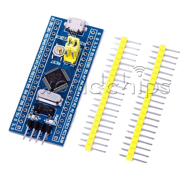
Current price was $4.66 USD on eBay, which makes them more expensive than the Maple Mini clones on AliExpress
So they are not such a good buy. Buy a Maple mini clone unless you can get this board very cheaply
I also have another STM32F103C8 based board
http://www.ebay.com/itm/ARM-Cortex-M3-S … 3a8bb339b5
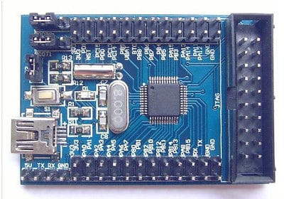
This board is listed at over $6 on eBay at the moment. It is the same chip as the other board, and as its even more expensive, I would not recommend buying it.
Now onto some boards that may be worth considering
If you need more RAM and Flash, you could consider one of these
http://www.ebay.com/itm/STM32F103RC-Bre … 418ddb0529
Around $11 on eBay
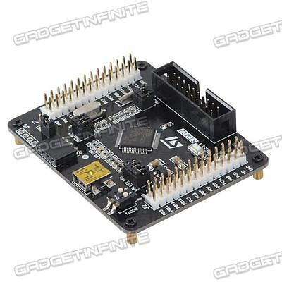
It uses the STM32F103RC chip, which has more Flash and Ram, and also 2 hardware DAC’s etc
However a problem with the board I received was poor build quality, the Boot0 / Boot1 switch was defective, and it took me a while to work out why I could not upload to the board.
But it was Ok after I replaced the switch by solder links.
Last but not least (quite the opposite) is this STM32F103ZET board
http://www.ebay.com/itm/1pcs-STM32F103Z … 43d32a0d10
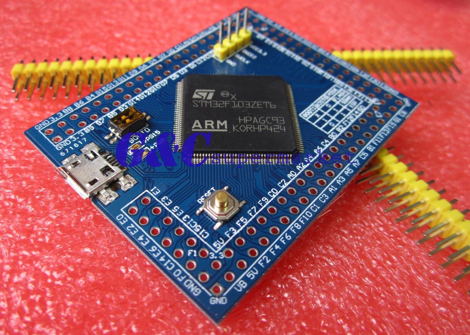
Currently $15.50 on eBay
Its virtually top of the line 512k Flash 64K RAM, 112 GPIO Pins !!
It also has external SPI Flash: W25X40BVSNIG and external EEPROM: AT24C08, on the underside of the board.
So is definitely worth considering if you need a lot of Flash or RAM or Pins.
When I get time, my plan is to connect a 3.2 inch parallel interface LCD display (however I will need to port the library for the display)
Finally.
I also have a “Maple” clone board. (Not a Maple mini, but a full Maple)
It was bought from iTeadStudio in Hong Kong
http://imall.iteadstudio.com/im120411012.html
Its not particularly good value for a STM32F103RB based board, at $13 on Special offer and over $40 when at full price
However the build quality is very very good. So for anyone setting up a classroom where you need a more robust board, a bit like a Uno, it could be worth considering, if they retain the special offer price.
PS.
I will turn this into a sticky when everyone has had their say.
Ray
http://www.aliexpress.com/item/leaflabs … 03487.html
![]()
http://www.ebay.com/itm/1pcs-STM32F103Z … 43d32a0d10
Currently $15.50 on eBay
Its virtually top of the line 512k Flash 64K RAM, 112 GPIO Pins !!
It also has external SPI Flash: W25X40BVSNIG and external EEPROM: AT24C08, on the underside of the board.
So is definitely worth considering if you need a lot of Flash or RAM or Pins.
I’ve not tested every single pin individually, but the on board LED is connected to pin PG15 i.e the last pin on port G (the last port), and that definitely works OK
The reason it works is that each board “variant” has a separate folder, which contains separate setup files, so i made a PIN_MAP definition that went all the way up to PG15
But, I didnt put a lot of effort into the PIN_MAP for the pins above PC15, so those pins probably don’t support PWM etc like the should do, they probably only do GPIO
But, its just a question of going through the manual and assigning the correct internal timer channel etc to each of the pins that are missing PWM (assuming the pin has an associated timer that can be used or PWM of course)
Edit.
We now also have support for the F103V Series
About the only F103 chips we don’t have support for are the VGT and ZGT i.e the ones with even more memory as we only support up to the VE and ZE versions
We’d only need to make some new linker files to support these, but as no one has one, we’ve not bothered making the files for them yet.
I’ve not tested every single pin individually, but the on board LED is connected to pin PG15 i.e the last pin on port G (the last port), and that definitely works OK
The reason it works is that each board “variant” has a separate folder, which contains separate setup files, so i made a PIN_MAP definition that went all the way up to PG15
For the “generic” boards, we started off by using an external USB to Serial adaptor, as the STM32 has an internal hardware bootloader that accepts Serial uploads on its hardware Serial 1 port (PA9 and PA10)
We have also added the feature to upload via STLink which is STM’s version of the SWD interface that I think all Arm processors support
However recently, we’ve realised that most of the “Generic” boards have a 1.5k resistor between the USB D- line and VCC which means the D- line is pulled high when the processor is reset, Or if the USB pin on the uProcessor for USB D- is switched from USB mode to GPIO mode we can drive it high and low to force USB re-enumeration.
This means we now have a version of the Maple Bootloader, which uses DFU to upload the sketch.
So once you’ve initially flashed the new bootlloader to the board, you can disconnect the USB to Serial adaptor and plug the board into the PC etc on its native / in built USB connector, and upload as if it was a “Maple” or “Maple mini”
Credit for the new bootloader goes to Victor PV who implemented the idea’s they were circulating on the forum (I’m not sure if it was originally my idea to someone else’s to use the GPIO etc)
I have loaded Victors new bootloader onto my ZET board and it works fine.
I was hoping to unify Victors version and the original Maple bootloader into one code base, but at the moment I have some issues with this (i.e I cant get it to work )
But I’m sure in the long term we will have one code base and conditional make e.g. make maple-mini or make generic-stm32z-series etc
Actually it looks like we only need 2 versions of the generic board bootloader, one for “Medium density” devices that have a 1k flash page size (generally this is the STM32F103C series of uP’s) and another for all other series of uP’s (which have 2k flash page size)
Actually we may be able to determine the flash page size programmatically in the bootloader, but as Victor only got it working a few days ago we’re not at that stage yet !
Actually we may be able to determine the flash page size programmatically in the bootloader, but as Victor only got it working a few days ago we’re not at that stage yet !
Instructions for new members of the forum sound good.
Do you think putting it in the Welcome posting is enough or do I need to do something else.
I’m really just finding my feet at the moment with PHPBB and I’m not fully aware of how to do those sorts of things.
I know how to convert a post to a sticky but thats about it ![]()
Instructions for new members of the forum sound good.
Must have been a Freudian slip ![]()
F103ZET ?
i think i’ll have a problem finding a db9 connector:-)
although if i go delving on the 3rd floor i might find a cable or two, about 12yrs since i knew precisely what’s up there!
probably go in via a9/a10, can i assume that route is standard across at least STM32F1nnaaan
if i have say 4 boards to photo & post, each in their own or just one post?
top & bottom of each
stephen
Personally, I’d try flashing the generic bootloader, it works fine on ZET6 boards (I have one, but its a much smaller footprint), you just need to pick a generic bootloader with the LED for where you have a user controllable LED on the board.
If none of the existing bootloader have the LED in the right place, just use the generic PC13 bootloader and either recompile the bootloader to suit your board or let me know which pin the LED is on, and I’ll add an new config and build a new bootloader for that LED position.
Also if you have a User button, this can be configured into the bootloader to enable you to use “perpertual” bootloader mode (where it locks it waiting for DFU upload).
But the button is optional
i think i’ll have a problem finding a db9 connector:-)
although if i go delving on the 3rd floor i might find a cable or two, about 12yrs since i knew precisely what’s up there!
probably go in via a9/a10, can i assume that route is standard across at least STM32F1nnaaan
if i have say 4 boards to photo & post, each in their own or just one post?
top & bottom of each
stephen
funny thought – any way to put an image in the title field of a post?
maybe like a file manager display as icons view / presentation?
stephen
Im new here and I dont know if this is the right place to post, but here is kind of a Discussion about the different boards, so i hope you will unterstand. Ich bought the little blue Board from ebay linked here:
http://m.ebay.de/itm/STM32F103C8T6-STM3 … 0408.m2460
So my question:
Is there a possibility to programm this Device via USB without an STLink or an USB to Serial Converter ?
I want to keep it simple and just programming over the Arduino IDE. Which kind of Software I have to install for the USB-Connection. How I have to config the bootloader?
Steps I try:
-Downloading the STM32-Master-File from Roger and packing into the hardware folder
-Installing the Drivers out there
-Looking for the youtube Videos from Roger
-Try to load a Sketch from the IDE, but here couldnt find the device
I also dont found the Leaflabs-Devices list in the Arduino IDE. Just the STM-Devices. I seen them on Rodgers Video but have no Idea where I get them.
Using Windows 7.
Hope you can help me with this.
With Regards from Germany
Maxi
Its a very common board.
Search if you search the forum or look in the wiki.stm32duino.com there is loads of information about it, including how to replace a resistor to make the USB work
Using one of them you can flash a bootloader for these boards and you can use USB for flashing.

