I’m currently working with arduino nano and have done a “small project”. But I’m running out of flash..
My problems: flash space has ended and I want to replace SoftwareSerial with real hardware UART. I need 2 UART:s.
In Arduino I use: attachInterrupt, reading pins statuses, hw uart, OLED with with u8glib. OLED lib can be any other since I’m displaying basic text only
Getting hw debugging to work with Arduino Nano is not possible (or not easy) and involves buying AVRDragon and some mods to Nano.. so I’d like to try that out with STM32.
What board do you suggest if I want :
1. to have a board with support for what my project uses and hw debugging capability. I’ve looked at Nucleo F103RB which has STLink
2. smallest size factor with minimum of 2 hw uart. Maple mini ?
Other questions:
Can I debug code in stm32 written with Arduino libs step-by-step in IDE ? Is it a difficult thing to set up and does it work like debugging with PC’s.. i.e. press one button. I’m not afraid of pressing two buttons but … you get the idea ![]()
Thanks!
To understand debugging, you will need to review some of the forum articles:
https://www.google.com/webhp?sourceid=c … 2duino.com
I would not put BMP into the “easy” category, but it is not all that complex. If you are pretty good with Arduino, you may find that just using Serial.print() is the better approach as debugging can be complex for a complex application… or, to rephrase: the complexity of debugging follows the complexity of the application.
Everything in this forum is indexed by Google, so the search using the “site:STM32duino.com” is a great way to find stuff quickly.
Look over a few of my simple (example) STM32 Maple Mini projects if you like to see if they fit your need:
https://www.hackster.io/rayburne
Ray
They both have the same mini-usb connector and fit nicely on a breadboard.
There are three hardware serial ports in addition to the usb port.
See viewtopic.php?f=27&t=68 for the pin numbers.
The maple mini reminds me of a Leonardo in the Arduino family.
There is a good bit of overhead needed for basic device operation, so a minimum sketch is about 15K and v2 of the bootloader takes another 8K. That still leaves 100K available for your application.
Another thing is that the maple mini is 3.3V while the nano is 5V. You’ll need to make sure that any external devices are compatible with the lower voltage.
Ray: you have some interesting projects for STM32 – helps me to get started. Also nice to see you use Arduino libs!
Looks like I’ll be ordering Maple Mini and Nucleo-F103RB to start with. It’s a big improvement for me since Maple mini has 3 USART ports compared to nano’s 1. Two for the comms and one for the debugging. That’s great – simple Serial debug works for the 99% of the time.
BMP looks sweet, yes. I’d probably like to evaluate free alternatives first. I just read an article about OpenOCD and setting it up with Eclipse: http://www.carminenoviello.com/en/2015/ … eo-part-2/ <– I find that quite easy.
Are there any other alternatives besides BMP and OpenOCD. EDIT: Sorry if this sounds like a silly question but is OpenOCD necessarily needed. What does it provide compared to bare stlink utilities ?
<…>
Ray: you have some interesting projects for STM32 – helps me to get started. Also nice to see you use Arduino libs!
<…>
Are there any other alternatives besides BMP and OpenOCD. EDIT: Sorry if this sounds like a silly question but is OpenOCD necessarily needed. What does it provide compared to bare stlink utilities ?
If you want a better board look at the F103RC or F103V or F103Z series boards.
The RB much closer to the functionality of the CB than the RC.
I recall @madias posted a link to a really good RC board a few weeks ago.
I’d advise you see if you can find his post and checkout that board in preference to the Nucleo
My recommendation for people who need a “big one” all inclusive board: viewtopic.php?f=28&t=490 –> the link, that Roger recalled
My recommendation for people who need a “big one” all inclusive board: viewtopic.php?f=28&t=490 –> the link, that Roger recalled
My recommendation for people who need a “big one” all inclusive board: viewtopic.php?f=28&t=490 –> the link, that Roger recalled
My recommendation for people who need a “big one” all inclusive board: viewtopic.php?f=28&t=490 –> the link, that Roger recalled
Michael: Please read my link about the 103VET6 carefully:
It has no ST-Link, but a second USB plug, this is connected to Serial1 via a USB-serial-converter. So you can totally easily debug the device via serial.
If you are going to experiment with STM32 a external ST-Link is a “must have” they are soooo cheap and useful!
Please note, that although it is possible to debug using STLink, we have not been able to find a GUI for Windows for GDB, so on windows, you’d need to use the command line debugger.
On Linux and possibly OSX, the DDD GDB GUI is possibly your best option.
I just bought R103RB nucleo because they were available on the local shop and did not want to wait many weeks for Maple Mini to arrive. Successfully finished setting up for Arduino IDE. Compiling and uploading works. Very nice. Now trying to find out correct GPIO for this 103RB-nucleo board to get Blink working ![]()
EDIT: for some reason I can’t see leds blinking. Is there something wrong with pin numbers (PA5, PB13). I’m referring to
User manual: http://www.st.com/st-web-ui/static/acti … to,124,556
void setup() {

// Set up the built-in LED pin as an output:

pinMode(PB13, OUTPUT);

pinMode(PA5, OUTPUT);
}
void loop() {
digitalWrite(PA5,!digitalRead(PA5));// Turn the LED from off to on, or on to off
digitalWrite(PB13,!digitalRead(PB13));// Turn the LED from off to on, or on to off
delay(1000); // Wait for 1 second (1000 milliseconds)
}
https://github.com/rogerclarkmelbourne/ … /infos_pdf
https://github.com/rogerclarkmelbourne/ … /infos_pdf
First question is what these modifications do ?
At first:
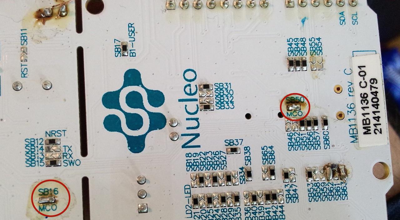
Nearly all STM32duino compatible boards have their own 8MHZ oscillator. Sadly ST saved a few Cent and didn’t fit the 8MHZ OSC (“HSE”) on the main MCU . Maybe there are some possibilities to setup the (inaccurate!) high-speed OSC in the config file. But I wont do that. The easiest way is to “highjack” the 8-MHZ OSC from the ST-link unit (the one above the blue button) and use it as HSE. This can be done with
– Desolder the 0-‐Ohm-‐resistors on SB55 and SB54 (bottom right) to cut the trace.
– Solder a little bridge on: SB16(MCO) (top left) and SB50 (bottom middle)
So this is the only necessary step using the nucleo for STM32duino and you’ll get your first blink sketch working!
All other mods are for routing serial stuff. Maybe you like it – or not.
Only modify the OSC won’t harm your nucleo in other IDE`s – on the contrary: Now you have the choice to use a accurate main HSE OSC!
First question is what these modifications do ?
At first:
Nearly all STM32duino compatible boards have their own 8MHZ oscillator. Sadly ST saved a few Cent and didn’t fit the 8MHZ OSC (“HSE”) on the main MCU . Maybe there are some possibilities to setup the (inaccurate!) high-speed OSC in the config file. But I wont do that. The easiest way is to “highjack” the 8-MHZ OSC from the ST-link unit (the one above the blue button) and use it as HSE. This can be done with
– Desolder the 0-‐Ohm-‐resistors on SB55 and SB54 (bottom right) to cut the trace.
– Solder a little bridge on: SB16(MCO) (top left) and SB50 (bottom middle)
So this is the only necessary step using the nucleo for STM32duino and you’ll get your first blink sketch working!
All other mods are for routing serial stuff. Maybe you like it – or not.
Only modify the OSC won’t harm your nucleo in other IDE`s – on the contrary: Now you have the choice to use a accurate main HSE OSC!
OK: You just need to close each of the two jumper with a little wire – see photo:
OK: You just need to close each of the two jumper with a little wire – see photo:
Use my test sketch first to found out, what “Serial” is connected if no mod is installed (should be “Serial1” or “Serial2)
#define ledpin 13

boolean flip=0;

void setup() {

// initialize serial communication at 9600 bits per second:

Serial.begin(9600);

Serial1.begin(9600);

Serial2.begin(9600);
pinMode(ledpin,OUTPUT);
}
void loop() {
flip=!flip;
digitalWrite(ledpin,flip);
Serial.println("Serial0");
delay(100);
Serial1.println("Serial1");
delay(100);
Serial2.println("Serial2");
delay(100); // delay in between reads for stability
}
D8/PA9 –> Serial2
D31/PC10 –> Serial0
D0/PA3 –> No output (because serial hw mod not done ![]()
edit: If it’s not shown as “Serial0” you can modify the nucleo board.cpp file :
Arduino/hardware/Arduino_STM32 /STM32F1/variants/nucleo_f103rb
The with the last entries (scroll down) you can set the Serial port shown up as USB-Serial (Serial0):
#ifdef SERIAL_USB

DEFINE_HWSERIAL(Serial1, 1);

DEFINE_HWSERIAL(Serial2, 2);

DEFINE_HWSERIAL(Serial3, 3);

#else

DEFINE_HWSERIAL(Serial, 3);// Use HW Serial 2 as "Serial"

DEFINE_HWSERIAL(Serial1, 2);

DEFINE_HWSERIAL(Serial2, 1);

#endifboard.cpp
{GPIOA, NULL, NULL, 5, 0, ADCx}, /* D13/PA5 LED - no ADC12_IN5 !*/board.cpp
{GPIOA, NULL, NULL, 5, 0, ADCx}, /* D13/PA5 LED - no ADC12_IN5 !*/board.cpp
{GPIOA, NULL, NULL, 5, 0, ADCx}, /* D13/PA5 LED - no ADC12_IN5 !*/