====
As it has been discussed in this forum, writing a continuous stream of data to an SDcard is difficult.
Not because of the SDcard’s writing speeds, but because of Write Latencies (up to 250ms).
During an WL an SDcard does not respond to the incoming data, it means when the data are not buffered, the data are lost.
You have to overcome the WL outages (random occurence, frequent, random duration) somehow, here is an example with a “FIFO buffering”.
More on this WL issue you may find here:
http://www.stm32duino.com/viewtopic.php … 288#p18207
Below you may find a complete Demo I wrote for MapleMini and an SDcard connected to SPI1:
1. we sample 8ADCs, 200x per second,
2. we apply 30Hz low pass filter on each ADC channel measurement,
3. we write the data into the FIFO buffer,
4. in parallel we read the data from the FIFO and write the data onto an SDcard as fast as we can,
5. the format we write the data on the Sdcard is CSV, so you may analyze what is going on in Excel,
6. we also log information on FIFO statuses (the values of counting semaphores).
Note:
1. In this demo we read 8ADC channels as an example, but some ADC channels read SPI1 signals,
as you may see on the results in the CSV file,
2. You may play with FIFO size in Records (here default 150), the actual content of a Sample Record, and with
Sample period/rate (default 5ms =200Hz) such it all fits into MapleMini memory (we assume you got 20kB ram)
and you do not get FIFO overruns when an WL hits,
3. I’ve tried to comment the code as the time permitted,
4. Provided As-Is, no warranties of any kind,
5. Use at your own risk.
Enjoy logging,
Pito
As you seem to know the system, I have a 16 mega-word buffer that could be treated as a FIFO. Would this work or is the SD Card going to hiccup before then? You mention 20K, have you tried dumping that much? Just trying to understand the buffer sizes
====
FIFO_size = data_rate * max_expected_sdcard_write_latency
Example:
====
You sample 100bytes 500x per second.
data_rate = 100 x 500 = 50kB/sec (this is the speed you want write data to the sdcard).
max_expected_sdcard_write_latency = 250msec
FIFO_size = 50kB/sec * 0.25sec = 12.5kB
Would this work or is the SD Card going to hiccup before then? You mention 20K, have you tried dumping that much? Just trying to understand the buffer sizes
Mind the writing the data to the FIFO AND to the Sdcard is done “in parallel” – thus it does not matter how the FIFO is large (provided it has been designed large enough for the given purpose) ![]()
You do not “dump” the FIFO in a single shot – it is a continuous process done in parallel – you pushing the data into FIFO AND data from FIFO into the Sdcard at the “SAME” time.. Look at FifoFree and FifoData in the resulting .csv file – when an WL occurs the FifoFree starts to decrease and FifoData increases (sample after sample) – after the WL is over, the process reverses itself..
Try the example/sketch source above – it uses almost all ram available. Also mind in the sketch it uses FIFO size of 150 “records of data” where the record consist of many items, and it writes the items as a READABLE_TEXT into the .CSV file – thus the datarate is the amount of TEXT CHARS (inclusive commas, spaces, \r\n) plus other additional info written to the Sdcard per second..
Also read this topic: http://www.stm32duino.com/viewtopic.php … 288#p18207
What I really meant was how much can one stuff into the SD Card buffers before that WL must happen?
I can re-write for the large external FIFO but need to know if it’s useful or not. I need to dump about 2M/second
-edit- OK I just saw in the other thread you had mentioned >2Megs / WL so I guess it’s worth to pursue
So with a very large RAM / FIFO buffer, continuous streams at 500K/S could easily be realized by streaming to the
SD card at, say 750K/S so the take-up max time of 250mS won’t ever be an issue.
Thanks!!
..But there must be a limit on the amount of data the SD Card can hold before transferring it in the flash cells…
-edit- OK I just saw in the other thread you had mentioned >2Megs / WL so I guess it’s worth to pursue
2) So with a very large RAM / FIFO buffer, continuous streams at 500K/S could easily be realized by streaming to the
SD card at, say 750K/S so the take-up max time of 250mS won’t ever be an issue.
3)..But there must be a limit on the amount of data the SD Card can hold before transferring it in the flash cells…
1) No idea, it depends on the actual SD card, the WL is a “random” effect..
2) The max data streaming rate depends on the MCU performance, SDcard type, SDcard interface parameters – ie. SPI clock freq., type of interface – SPI or SDIO, etc.
3) It depends on the actual SDcard – the card’s HW differ, firmware differ as well, so hard to answer..
The best way is to experiment and measure..
WL is random makes sense now, guess it’s off to the scientific experiments
Cheers,
Sandy
EDIT: Found one with buffered chip:
The whole setup has to be 3.3V straight.. The only thing which is important is the SDcards are 3.3V, so a voltage regulator is needed when the SDcard is powered from 5V, and good decoupling (between VCC3V3 and GND) close to the SDcard (ie 2x 10-22uF ceramic multilayer).
There will be a maximum of 20 readings to be output.
So, question, am I likely yo be impacted by this or is my output volume ‘under the threshold’?
Double check wiring. The sdcard module needs 3.3V.
minor edit
I have been working on arduinos for a few months now and how I understand the SD library works is by creating a 512B buffer and every request to Write on SD is pushed on to the Buffer. The buffer is finally written on SD card when its nearing full. So when I compute the time required for writing data to SD card in a loop a byte at a time, I get like few dozen microsecs for most transactions and one odd write in the range 5-200 ms (or maybe more at times).
When we use the RTOS implementation is the same basic being followed? If yes, then would someone elaborate on the given situation
-The producer thread produces 1B every ms and that needs to be written to SD card.
-The consumer thread just writes to SD card.
The producer thread being of higher priority is woken up every ms and the task it does takes about 300micro secs(say). So when the SD library buffer fills up and its time to actually write to the SD card. The CPU makes access request to write to SD card and due to the latencies involved being of the order of several ms, the request is interrupted in between and the cpu switches to producer thread which writes to the FIFO as usual. After doing its task, the producer sleeps again and the request generated by the consumer thread, which was interrupted in between earlier, is re-initiated again resulting in generating similar write latencies as before. By this logic a successful write can never take place, but since it does I know that my understanding of its functioning is flawed.
I need to understand this so that i can structure my code accordingly. Thanks in advance. i know my explanatory (if thats a word) skills are a mess.
So you have your writer thread waiting for the SDcard to respond to a command, but the sdcard is busy doing whatever an sdcard does, and will take 50ms to respond. In this case the writer thread must be in a loop waiting for the correct reply right?
While in that loop, the scheduler interrupts it and resumes a different thread (call it sensor thread), which takes 500uS to complete, and then goes to sleep for 100mS. When the sensor thread goes to sleep, the scheduler looks at what is the next active thread to run. The writer thread was not sleeping, it was waiting in a loop and was interrupted, so when resumed goes back to that same loop, and keeps waiting for the correct reply from the sd card.
That thread can be interrupted and resumed many times while in the loop, but eventually the sdcard replies back and the writer thread continues with it’s writing process.
Does that clarify it?
Imagine worst case latency 250ms. And you want to write (sensor task) 10kB/sec onto the card (now it does not matter on task timings).
So the FIFO buffer shall be 0.25sec * 10kB/sec = 2.5kB large.
When assuming the writing to the SDcard is much faster as the writing speed of sensor’s task to the fifo buffer, it will not overrun during the 250ms.
The timing: as victor wrote it is a preemtive multitasker, so the sensor reader will write at 1ms intervals say 3Bytes (3kB/sec) into the FIFO buffer.
“In parallel” (that is the rtos’ trick) the SDcard writer attempts to write onto the SDcard from the FIFO buffer full speed (ie 1MB/sec) when FIFO is not empty. While the FIFO fills itself from left side at speed 3kB/sec, it empties itself from right side at speed 1MB/sec, all in parallel, sometimes blocked at the right side by the write latencies.
Normally the FIFO will be all the time empty. When the write latency hits, the FIFO starts to fill itself (like a bottle). The size of FIFO will be enough for planned latency. When latency finishes, the SDcard writer will flush the FIFO onto the SDcard full speed (1MB/sec).
When you run my example above, play with it and observe the .CSV data, you would see how it works in detail.
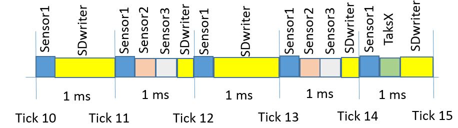
The switching:
My current understanding is, the switcher, when completes the “Sensor” task (say at 300us from the start of the 1ms tick as an example), switches over and starts the another task – the task SDwriter – immediately.
It happens say at 301st microsecond from the start of the 1ms tick as the example.
The Sensor task is scheduled to be run at 1ms intervals (the sampling period in ticks), but the SDwriter is “always” ready to continue with writing the data off the FIFO to the SDcard (when FIFO not empty)..
So the SDwriter does not wait till the next Xth 1ms tick to continue with writing to the SDcard..
When you have planned several tasks to be started and run at Xth tick, the scheduler attempts to run all planned tasks at the Xth tick (in round-robin sequence when tasks at same priority). When say all 3 tasks will finish at 820us from the start of the Xth tick, the SDwriter will continue immediately with writing onto the SDcard from 821st microsecond..
- Scheduling.JPG (43.49 KiB) Viewed 783 times
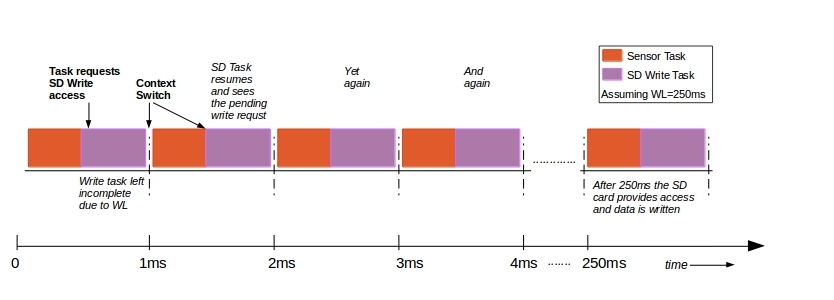
1) Lets assume as in the figure, the SD Write Task requests write access in the tick corresponding to t=0 and encounters latency (250ms assume). So until the 250th tick every time, the scheduler switches to the SD Write Task , the task only waits for the request to be served?
2) So what happens when the Sensor Task takes, say 800us to complete and the SD task is left with only 200us before the preemption takes place.
In this case since the actual write is of 512B (which is the cache size as defined in, I believe in “FatVolume.h” ;not the FIFO buffer declared by user at compile time) and may take like 1.6ms @ 300KBps (minus the latency). So to say, that the writing task (when actually writing to card) is interrupted (as it has only a 200us time slice) and it will complete the transaction in 8 such ticks (1.6ms / 200us).
- forum.jpg (53.18 KiB) Viewed 771 times
My above Logger example does log the timings (in usecs) between the actual sampling periods onto the SDcard together with data, so you may inspect whether it dropped a measurement or not.
Of course, you can get FIFO overruns when the timing is critical and you do not have enough FIFO buffer space available. When the FIFO cannot be emptied fast you get overruns (they are logged as well together with the FIFO watermark at each sample measurement) and some amount of your data is lost until it recovers.
Simply try it and report ![]()
The example logs with each sample measurement:
void PrntHeaders () {

// Print Data Record Headers into the CSV file

file.print(F("Time_us"));

file.write(',');

file.print(F("ADC0"));

file.write(',');

file.print(F("ADC1"));

file.write(',');

file.print(F("ADC2"));

file.write(',');

file.print(F("ADC3"));

file.write(',');

file.print(F("ADC4"));

file.write(',');

file.print(F("ADC5"));

file.write(',');

file.print(F("ADC6"));

file.write(',');

file.print(F("ADC7"));

file.write(',');

file.print(F("Overruns"));

file.write(',');

file.print(F("FifoFree"));

file.write(',');

file.println(F("FifoData"));

}
If two tasks use the same resource (ie SPI1) you have to use the mutexes to lock the resource when used.
If producer uses the SPI1 and consumer the SPI2 there is none problem.
FYI – the SPI1 runs up to 36MHz (@72MHz base). And the BluePill runs up to 128MHz overclocked. So forget 8bitters
How did I miss multiple SPI ports on the pills. I suddenly am starting to feel the richest man alive!!! Guess it will take some time for me to get used to the riches… gonna have a tough time trying to get some sleep tonight out of excitement!!!
Hope the STM32duino library base soon reaches the Teensy level. That would be the end of AVR era as we know.
Default:
. Sampling period set 1ms
. Writes about 20bytes per sample (a record) into a DATA.CSV file (time[us], ADC1, Overruns, FIFOFREE, FIFODATA)
. No FIR filter on ADC
. Uses 400 records deep FIFO
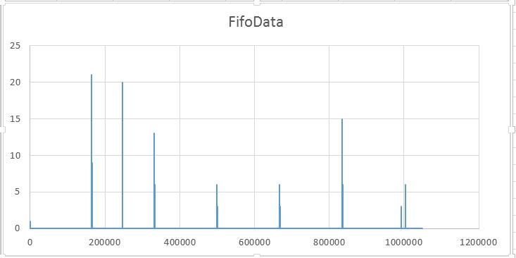
Here it runs without overruns with a mainstream SDcard. Below is the FIFODATA from excel indicating there were 3 latencies which took up to 190 records in FIFO. The jitter you may see from the logged data is 1-2usec from time to time (but 0 most of the time).
Compiled for Maple Mini, for BluePill or others you have to adjust the LED’s and SDcard’s /CS pins.
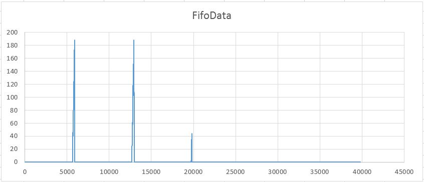
- Fifo Data.JPG (36.65 KiB) Viewed 724 times
Thanks a lot!!
Any suggestions?
Thanks
If not, you have to rename Serial1 to Serial (usb) everywhere in the source.
void setup() {

// Tasks creation statuses

portBASE_TYPE s1, s2, s3;
Serial1.begin(115200);
Based on the results you may play with FIFO’s size. Mind a bigger latency may hit after a longer capture period.
    // Print out the Data Record values into the CSV file
if (last) {

file.printField(p->usec - last,',');

} else {

file.write("NA , ");

}

last = p->usec;

file.printField(p->value1,',');

file.printField(p->value2,',');

file.printField(p->value3,',');

file.printField(p->errors,',');

file.printField(p->a,',');

file.printField(p->b,'\n');
// Advance the FIFO index
FIFO size 400 records. No data lost.
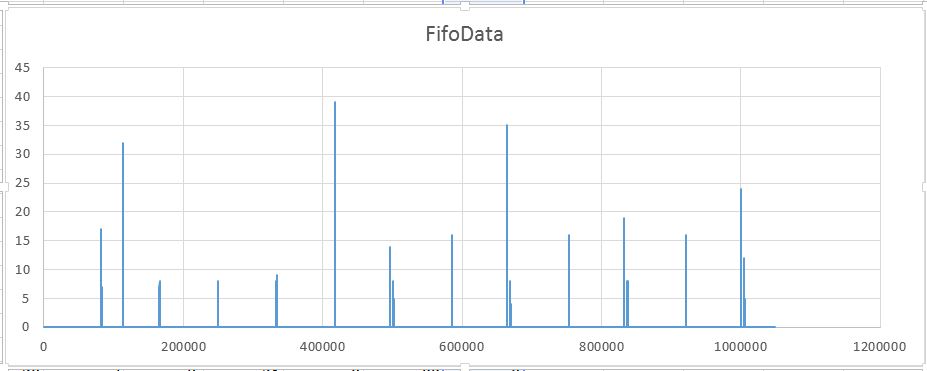
You may see how the fifo messed with critical timing (it seems the 1ms sampling with above amount of data is at the edge of system’s ability to process the data) and sdcard’s write latencies (only first 1.048mil samples shown for obvious reason):
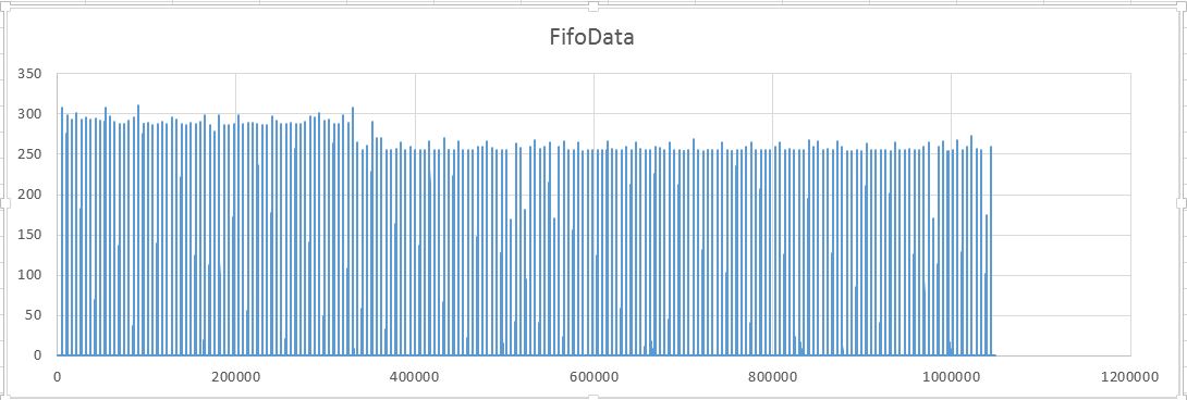
- Log 1ms 1mil.JPG (71.08 KiB) Viewed 612 times
You may go with much smaller FIFO size, as the picture indicates.
The rd/wr speed of EX (Extended Transfer Class) is much higher than with a standard SdFat (and you do not need large caches to get such speeds).
In practice it means you may log much more data with the 1ms sampling. Try ![]()
- Log 1ms 1mil SdFatEX.JPG (29.15 KiB) Viewed 595 times
The sampling includes 8xADC and 67taps low-pass FIR filter applied on each ADC channel.
With FIFO size 100, I’ve got zero errors, no data lost.
We write 50-60bytes per sample (we write .csv text), that is 50-60kB/sec data onto the sdcard.
- Log 1ms 1mil 8ADC FIR SdFatEX.JPG (40.45 KiB) Viewed 578 times
If I want to log lesser channels I only have to comment out the others like in this example with only the three first cannels?
    // Record the ADC data read from the Sensors into the FIFO

// Sampling of 8 ADC with 71taps fir filtering takes 285usecs

p->value1 = analogRead(PA0);

p->value2 = analogRead(PA1);

p->value3 = analogRead(PA2);

/*

p->value4 = analogRead(PA3);

p->value5 = analogRead(PA4);

p->value6 = analogRead(PA5);

p->value7 = analogRead(PA6);

p->value8 = analogRead(PA7);

*/

SampleFilter_put(&f[0], (int) p->value1);

p->value1 = SampleFilter_get(&f[0]);

SampleFilter_put(&f[1], (int) p->value2);

p->value2 = SampleFilter_get(&f[1]);

SampleFilter_put(&f[2], (int) p->value3);

p->value3 = SampleFilter_get(&f[2]);

SampleFilter_put(&f[3], (int) p->value4);

/*

p->value4 = SampleFilter_get(&f[3]);

SampleFilter_put(&f[4], (int) p->value5);

p->value5 = SampleFilter_get(&f[4]);

SampleFilter_put(&f[5], (int) p->value6);

p->value6 = SampleFilter_get(&f[5]);

SampleFilter_put(&f[6], (int) p->value7);

p->value7 = SampleFilter_get(&f[6]);

SampleFilter_put(&f[7], (int) p->value8);

p->value8 = SampleFilter_get(&f[7]);

*/

// Record the FIFO overruns for this sample

p->errors = overrunerrors;

overrunerrors = 0; // clear for the next sampleYou have to comment out all places where you define/mess with those values.. A “record” consists of those values, thus you save a lot of space then.. (FIFO works with records)..
https://www.stm32duino.com/viewtopic.php?t=1298#p16742
post, becouse i need to increase the tick frec and i can’t do it. I configure
#define configTICK_RATE_HZ ( ( TickType_t ) 1000 )
in the RTOSconfig.h to 100 or to 2000, and no effect.
Can you help me??
At 1 ms tick it works perfect.
Thanks for all.
