Trouble is, once it’s synced, it drifts seconds after only a few seconds. Seems like one of the BP is like 80% the speed of the other one. Is this normal?
I’ll try to check later on the oscilloscope if there’s a significant clock difference between the two, but for now, could it be my code that’s doing something? I’m not touching the timers, only using a cooperative scheduler and an SPI device.
I’ve also yet to flash the latest bootloader, was there such a bug in the original maple bootloader?
I’ve also yet to flash the latest bootloader, was there such a bug in the original maple bootloader?
seems to show lack of knowledge on how things work: there is no relationship between the bootloader and your sketch timings..
If you want to keep 2 BP’s in sync with each other, you’ll need to use an external oscillator source and feed it to both the BP’s
You can buy cheap clock generator modules for around $5 (look for si5351)
That being said, the difference in clock freq you seems to have is much more than I’d expect.
BTW. you can manually “pull” the crystal (change its freq a bit) by using a capacitor
I posted a question about pulling the crystal a while ago (you’ll need to find the post yourself, as I can’t remember precisely what question I asked)
1) can’t H/W sync 2 different crystal oscillators / clocks (apart for freq. trimming with a variable capacitor)
2) Yes Xtals used in cheap boards are very cheap too and freq can vary BUT in no case with drift of secs in secs.
3) Only way to (H/W) sync is drive both with another external oscillator module.
Still please inlight us with more h/w or s/w details…
Nick
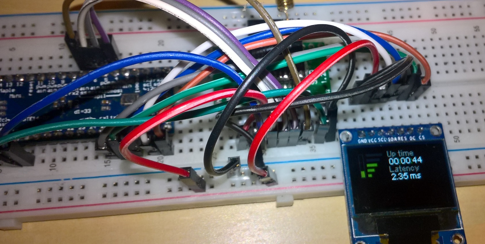
I’m building my library (https://github.com/GitMoDu/LoLa) to link 2 modules. With a timestamp OnConnectionEstablished both spit out the same clock, as can be seen on the example log I recorded (https://github.com/GitMoDu/LoLa/tree/ma … vices/Link).
(Host)
Link took 124 ms to establish.
Connected Synced TimeStamp: 1085381660
Connected
(Remote)
Link took 116 ms to establish.
Connetecd Synced TimeStamp: 1085381659
Connected
Both timestamps are within ~1 ms at Connecting time, that’s why I’ve discarded the clock sync mechanism as the culprit.
Then I tried logging each tick of seconds (in the loop, no interrupts) to compare both in real time. And sure enough, after about 5 seconds, one clock is already 1 seconds behind.
[edogaldo – Tue Sep 25, 2018 10:22 am] –
seems to show lack of knowledge on how things work: there is no relationship between the bootloader and your sketch timings..
This question stems from a series of topics on the bootloader, USB, clock frequency and its effects.
[RogerClark – Tue Sep 25, 2018 10:35 am] – That being said, the difference in clock freq you seems to have is much more than I’d expect.
Yes, I was expecting a few ms after a few minutes, at worst: this is orders of magnitude larger than I expected. This can’t be a Crystal precision issue, unless I have at least one really really bad board.
I’ll test other boards when I get home.
[RogerClark – Tue Sep 25, 2018 10:35 am] – If you want to keep 2 BP’s in sync with each other, you’ll need to use an external oscillator source and feed it to both the BP’s
I’ll look into it, would be nice to have a more reliable clock, even though ~1ms precision is good enough for my purposes. It would allow for more aggressive timings on other functionalities that rely on the synced clock (duplex masking, channel hopping, time based crypto.).
We don’t know what runs in the background so it is hard to find the root cause unless you provide a simple example how to reproduce it.
By reducing the code to simple example the people often find the issue themselves…
The timestamps simply a millis() with an offset.
uint32_t GetMillis()

{

return millis() + Offset;

}If the time drifts again a lot, then you have a problem with one of the boards.
and so there you go
https://github.com/rogerclarkmelbourne/ … time.h#L46
https://github.com/rogerclarkmelbourne/ … tick.c#L84
oh then if you are busy feeding that lcd over spi for the screen update, and listening for data returning from the sd card, i think for those microseconds interrupts are kindly disabled to focus on spi/dma so that you won’t miss the data from sd card or that lcd miss a stripe
https://www.keil.com/pack/doc/CMSIS/Cor … k__gr.html
http://infocenter.arm.com/help/topic/co … cjgga.html
Connecting the two units together is not an appropriate methodology since either unit, or both, are suspect as well as your software.
The uC clock on the Maple Mini and my blue pills seem to be rather good at managing serial communication to/from my Linux system at 115200 BAUD … IMHO that is good `nuff. Anything else should make use of an external time source such as a DS3231 or GPS (my last purchase was only $9.)
You could put your 2 `duinos into a box and shake vigorously in an attempt to quantum entangle them. ![]()
Ray
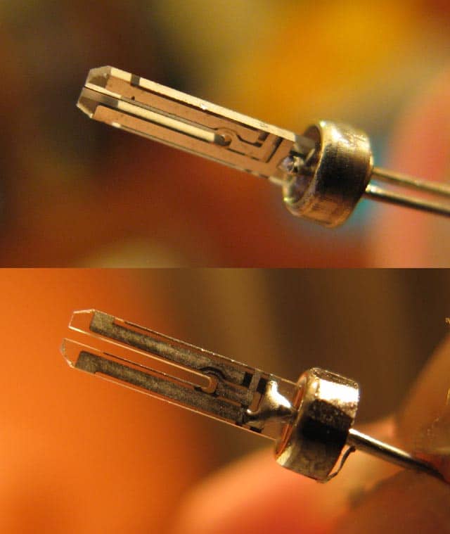
and as the legend goes, it isn’t about how many mhz your crystals can oscillate. rather even at that humble 32786 crystal there exist a high end high quality variety that meets the high tech laser trimmed and tuned *tuning fork* and *gold plated* standard that is sealed in *vacuum*, that meets the super lofty 6pf crystal standard that st sets for the world to live up to that may be looks like this
viewtopic.php?f=3&t=3896&hilit=32k+crys … =10#p47495
https://en.wikipedia.org/wiki/Crystal_o … _materials
then there exists another ebay/aliexpress 20 pcs for a dollar variety that you search using the special keyword 32768
https://www.ebay.com/sch/i.html?_nkw=32768&_sacat=0
and chances are that it looks like this on the inside
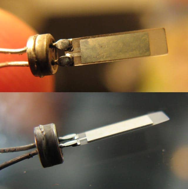
this type might be that big fat one piece variety almost likely > 10-15pf, uses simple solder if they happen to bond and *air sealed* (forget about the vacuum)
as for this type the chances of hitting 32768 on a parts per billion accuracy may be quite similar to the scholastics of buying lottery
but you may just get one that is right on the dot by pure chance
but then the internet it seemed never leave you without an option, u’d only need to add 6pf + 32768 as keywords
https://www.ebay.com/sch/i.html?_from=R … 8&_sacat=0
and there is even a tip from pito about a gimmick capacitor if there are no lasers to do all that trimming
viewtopic.php?t=671&start=10#p27426

![]()
(the 6pf ‘legend’ is on p13 2.2 note 1 ‘getting started hw dev stm32f10x
https://www.st.com/content/ccc/resource … 164185.pdf)
https://en.wikipedia.org/wiki/Clock_of_the_Long_Now
the reason is that bp/mm + that 32768 crystal last and runs so long as someone swap the coin cell and reset it say once a year
and the mountain of bp/mm for sure last a long time till i’m not sure when, oh i think solar cell is also possible just that the lipo battery backup may fail before the solar cell fail
on a fun note, i think the bp/mm is a fun piece to make a little digital clock project, the RTC do live for a long time on a single cr2032 coin cell.
i had a false start when a defective mm drained the coin cell in 2 weeks, i assembled a different one run it (the RTC) on a new coin cell, and it seem to keep the time ‘perpetually’. the bigger power e.g. from usb is necessary if you want to look at the time, e.g. on your lcd or over usb-serial. while offline the coin cell keeps the RTC running happily till you decide to power up the BP/MM again.
![]()
1) Did you tried with just 2 boards ? (if there is another one in place of first 2, what happens ? -just to short out a H/W problem in one of two boards)
2) If you just compare millis() i think time difference cannot be explained (except a h/w problem in one of the boards)
3) if you ARE comparing PLAIN millis() (w/o any other var. added) in any conditions (interrupts etc) time difference should not be that much (you’re saying for a sec drift in 5 secs period after initial lock) !!! This cannot be done ! I think for 2 RTC xtals to drift 1 sec apart, hours should pass, not secs…(eg. even a 100ppm xtal should need about 3 h to drift 1 sec…)
4) In my understanding you DON’T sync millis() but some other var that takes into account another -offset- var, calculated by code + protocol + Tx-Rx link etc… So you have a bug situation, not a H/W problem …..
Bare minimum would be 3 boards, or 5 boards etc, otherwise you have no way of knowing which board is incorrect.
I suppose it’s possoble there is some issue with millis() but considering how many people use it, and how much investigation there has been to its accuracy and stability, I am a bit surprised no one has noticed such big errors
I have used the timers to generate various frequencies and have not noticed any problems with the severity that the OP is experiencing
I did however had a dream about a water cannon, where when the cannon fired, it lost water pressure and the rollercoaster stopped and every one on the space shuttle was sad.
Anyway, I think this is a way of my brain telling me that I may be missing some brownouts when the RF is transmitting, because I remembering catching a lot of low voltage warnings (feature of the radio IC) a few weeks ago.
I’ll be back.
And in greater numbers.
[ag123 – Tue Sep 25, 2018 3:08 pm] –
…
and there is even a tip from pito about a gimmick capacitor if there are no lasers to do all that trimming
The twisted-wire is the old way that radio builders (and Ham Operators) used to fine-tune components. But “gimmick’ing” can be done in many ways; https://www.hackster.io/rayburne/gimmic … uino-16mhz
Ray
[mrburnette – Wed Sep 26, 2018 3:33 pm] –[ag123 – Tue Sep 25, 2018 3:08 pm] –
…
and there is even a tip from pito about a gimmick capacitor if there are no lasers to do all that trimmingThe twisted-wire is the old way that radio builders (and Ham Operators) used to fine-tune components. But “gimmick’ing” can be done in many ways; https://www.hackster.io/rayburne/gimmic … uino-16mhz
Ray
oh wow, that must be the most compact AT-Mega 328 pu with a crystal and load capacitors – ever ![]()
[ag123 – Wed Sep 26, 2018 3:37 pm] –
…
oh wow, that must be the most compact AT-Mega 328 pu with a crystal and load capacitors – ever
Every one I have made and tested works great @ 3.3 Volts, too. Of course, the Chinese Mini seems to do well at 3.3 Volts.
How to make electrolytic capacitors at home
https://rimstar.org/science_electronics … acitor.htm
and another
https://www.youtube.com/watch?v=–3wdn8fnqw
so if you need a super capacitor there it is, who needs ebay/aliexpress ![]()
https://www.youtube.com/watch?v=lzHqhNoyx2o
https://www.youtube.com/watch?v=Cl2LI0P9xSc
i’d guess that’s why some of the finest oscillator crystals come from japan
Ray
After thought on stability…
In any measurement system, one must have a standard by which measurements are referenced.
In U.S.A. https://en.m.wikipedia.org/wiki/Nationa … Technology
The reason I mentioned a GPS 1pps output is that for hobbyists, this is the most accurate time base that they can reasobably afford, under $20 and ofter $10.
IMHO, no lab or workbench that does any frequency measurements should be without one.
https://www.eevblog.com/forum/chat/how- … ps-signal/
https://playground.arduino.cc/Code/NTPclient
i think that should be pretty accurate as the stratum 0 are high end atomic clocks
https://en.wikipedia.org/wiki/Network_Time_Protocol
However, that leaves the bp/mm bounded to a host pc say over usb, hence i’d think ray’s suggestion of gps time is a good way.
As i don’t really need very high accuracy in my use cases, i used a hybrid method that uses the rtc for simple timekeeping and occasional time sync over usb when connected to the pc over usb, those cheap 20 for a dollar 32k crystals worked well enough for me
Turns our the answer is boring: faulty hardware.
The OLED I was using is broken and was hogging the SPI line with atomic calls which, expectedly, delayed the every interrupt.
[stevestrong – Tue Sep 25, 2018 2:23 pm] –
Take the two boards and use simple blinky code to output over (USB) serial the current millis() each second, and check the result.
If the time drifts again a lot, then you have a problem with one of the boards.
I have done so, no problems with bare boards.
[ag123 – Tue Sep 25, 2018 2:25 pm] –
if i’m not wrong millis() is actually the counts of the systick interrupts, if the processor is too busy perhaps it has no time to sent you the ticks and it skip a few/ many ticks (beats) every now and then, and systick interrupt can be easily disabled or overridden by higher priority interrupts, actually stm32 when it is running wth usb, dma & all that is a very busy processor, once you hook it up to usb full speed, usb interrupts stm32 every 1 ms to do some work e.g. send/receive the data, then the systick ticks every ms, if you add dma, other timers, adc interrupts, RTC interrupts, then maybe system exceptions etc, you may then need to examine if the processor still have any time between that 1ms timeslice
This trouble has led to understand a bit more the interrupt vector table and how micros are counted without relying on a 1us interrupt. Thank you for the links.
[ag123 – Tue Sep 25, 2018 2:25 pm] –
oh then if you are busy feeding that lcd over spi for the screen update, and listening for data returning from the sd card, i think for those microseconds interrupts are kindly disabled to focus on spi/dma so that you won’t miss the data from sd card or that lcd miss a stripe
Turns out the OLED was the culprit, it was hogging the interrupts with atomic calls, but only because the hardware is broken.
[mrburnette – Tue Sep 25, 2018 2:36 pm] –
I would prefer you use a guaranteed GPS 1-second pulse to gate both systems and compare the clocks using exactly the same methodology: interrupt or polling in loop().
Yes, from what I’ve looked into, this seems the best option to ensure a synced clock. I’d actually like to use that approach, but I want the GPS’less solution working as a fallback. Next feature to implement.
[mrburnette – Tue Sep 25, 2018 2:36 pm] –
Connecting the two units together is not an appropriate methodology since either unit, or both, are suspect as well as your software.
[mrburnette – Tue Sep 25, 2018 2:36 pm] –
You could put your 2 `duinos into a box and shake vigorously in an attempt to quantum entangle them.Ray
I laughed so hard at this, I think I might’ve actually put my job jeopardy ![]()
I think I’ll have to refrain from reading this forum in office, otherwise you’re gonna be the death of me, Ray!
[ag123 – Tue Sep 25, 2018 3:08 pm] –
Wow, what crazy weird world I know nothing about and feel so happy as such ![]()
Good stuff for a midnight read.
[EntropyWizard – Tue Sep 25, 2018 3:40 pm] –
Another angle you can use to track down this issue: Configure your MCO pin on the micro (pin A8) to output your system clock on each board, then measure the output with a counter or oscilloscope. This will verify both that your crystal is working, and that your clock configuration is correct.
Tried, using this lovely chap’s library. Unfortunately, my oscilloscope has 50 MHz bandwidth so it wasn’t really helpful as I could only see the lower harmonics and a ton of a aliasing. Time to hack the firmware to get it to 100 MHz (the DS1052E is firmware hackable to the upgraded version ![]() ).
).
[ag123 – Tue Sep 25, 2018 4:17 pm] –
https://en.wikipedia.org/wiki/Clock_of_the_Long_Now
Fascinating stuff, never heard about before.
[ag123 – Tue Sep 25, 2018 4:17 pm] –
on a fun note, i think the bp/mm is a fun piece to make a little digital clock project, the RTC do live for a long time on a single cr2032 coin cell.
I have yet to exploit the RTC, good to know it can useful in low power systems.
[nikosx – Tue Sep 25, 2018 6:21 pm] –
Ι’m still confused and don’t quite understand the problem (i think it lacks proper explanation / setup for a 3nd person like me to understand it). Some thoughts :
1) Did you tried with just 2 boards ? (if there is another one in place of first 2, what happens ? -just to short out a H/W problem in one of two boards)
2) If you just compare millis() i think time difference cannot be explained (except a h/w problem in one of the boards)
3) if you ARE comparing PLAIN millis() (w/o any other var. added) in any conditions (interrupts etc) time difference should not be that much (you’re saying for a sec drift in 5 secs period after initial lock) !!! This cannot be done ! I think for 2 RTC xtals to drift 1 sec apart, hours should pass, not secs…(eg. even a 100ppm xtal should need about 3 h to drift 1 sec…)
4) In my understanding you DON’T sync millis() but some other var that takes into account another -offset- var, calculated by code + protocol + Tx-Rx link etc… So you have a bug situation, not a H/W problem …..
1 – I tried changing boards, no effect. Thank heaves for 2$ BP.
2 – Yup, once the buggy OLED screen was out of the way, perfect sync every time.
3 – Yup, have test setup running for 10 minutes, millis are still in perfect sync.
4 – No bug.
Thanks for input
[RogerClark – Tue Sep 25, 2018 9:16 pm] –
Only using 2 boards for this test is also flawed.
Bare minimum would be 3 boards, or 5 boards etc, otherwise you have no way of knowing which board is incorrect.
I have box full of them :p But good point.
[RogerClark – Tue Sep 25, 2018 9:16 pm] –
I suppose it’s possoble there is some issue with millis() but considering how many people use it, and how much investigation there has been to its accuracy and stability, I am a bit surprised no one has noticed such big errorsI have used the timers to generate various frequencies and have not noticed any problems with the severity that the OP is experiencing
Absolutely, I have had no question there was something wrong on my side.
For the record, here are some sample logs without buggy hardware.
Host
Sleeping
Broadcasting…
Connecting to: 0x98 Session code: 242
Connecting Seed: 227
Connecting
Link took 96 ms to establish.
TOTP Seed 81126604
OnConnected Token: 158
Sync TimeStamp: 2134380068
Connected
2134381
2134382
2134383
(…)
2136274
2136275
2136276
Remote
Searching for Host…
Connecting to: 0xBA Session code: 242
Connecting Seed: 227
Connecting
Add Offset: 2134378013
Before: 0
After: 2134378013
Link took 89 ms to establish.
TOTP Seed 81126604
OnConnected Token: 158
Sync TimeStamp: 2134380067
Connected
2134381
2134382
2134383
(…)
2136274
2136275
2136276
After a few minutes, I start to get a 1-2 ms drift, something I can easily compensate.
Now that problem IS solved i think all make (at least some) sence…. ![]()
[RogerClark – Tue Sep 25, 2018 10:35 am] –
You can buy cheap clock generator modules for around $5 (look for si5351)
What would be your suggestion here?
Replacing the ceramic resonator crystal oscillator of the BP with this clock generator? Generating a 1kHz clock and use an interrupt to have my own Millis counter?
These badboys seem to induce literally error, so the accuracy is proportionally as good as the 25 MHz crystal, taking clock divisions into account?
As far as i know BP uses crystal for oscillator not a ceramic resonator (with much worse accuracy..)
i mentioned this to the arduino folks years back but they told me to take a hike, ![]() : the timing functions in arduino isn’t well written and the typical applications they will create jitter.
: the timing functions in arduino isn’t well written and the typical applications they will create jitter.
sounds like in your case, you didn’t have jitter but drifting (consistently faster or slower). in that case, check for clock accuracy and oscillator types. and code obviously if they aren’t running the same code.
