Roger encouraged me to make a post here, so here’s me ‘taking the plunge’. My first code-snippet / project.
From reading Vasillis code example using the PT8211 (thank you!), if spurred me on to create a dual LFO.
I was interested in getting two independant waveforms out of the chip with a choice of wave shapes, and a frequency between 0.1Hz and 100Hz.
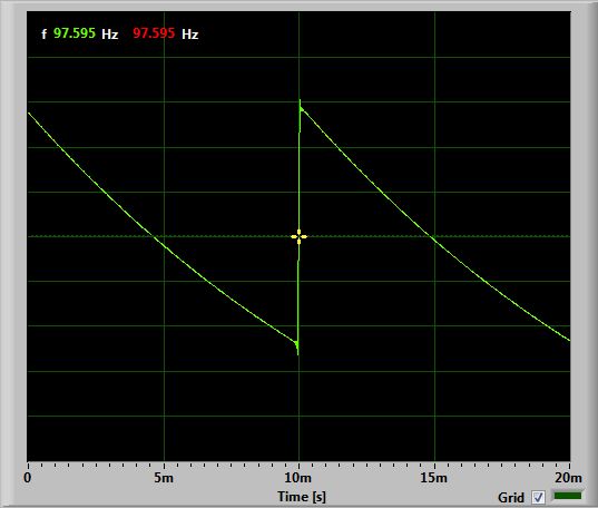
The code here seems to work fine. There is, however, an issue with the waveforms generated. Particularly at lower frequencies.
/**

Dual LFO for STM32F103C8T6
Description:
This code generates separate low frequency waveforms on the two channels of the PT8211 DAC.
My remit was for frequencies approximately between 0.1Hz and 100Hz (LFO) and a choice of waveforms
including sine, saw, reverse saw, triangle and square
Created by Ken Laszlo 24/11/2017
email: wight446-at-yahoo.com
Thanks to Roger Clark, Vassilis Serasidis and Madis
Connections between PT8211 DAC and the STM32F103C8T6
WS <--> PA3
BCK <--> PA5 <--> BOARD_SPI1_SCK_PIN
DIN <--> PA7 <--> BOARD_SPI1_MOSI_PIN
100K Potentiometers on PA2 and PA4 providing a scaled voltage between 0 and 3.3v for frequency selection
100K Potentiometers on PA6 and PA8 providing a scaled voltage between 0 and 3.3v for wave type selection
*/
#include <SPI.h>
#define WS PA3
#define BCK PA5
#define DATA PA7
#define SINE 0
#define SAWTOOTH 1
#define REVSAWTOOTH 2
#define TRIANGLE 3
#define SQUARE 4
int waveRead;
byte waveType1 = SINE;
byte waveType2 = SAWTOOTH;
int maxSamples1 = 512;
int maxSamples2 = 512;
int sampPos1, sampPos2 = 0;
int ratio1, ratio2;
int phaseAccumulator1, phaseAccumulator2 = 0;
uint16_t thisSample1, thisSample2; // 16 Bit as these will be fed to the DAC
// Sine generator
// http://www.daycounter.com/Calculators/Sine-Generator-Calculator.phtml
// Triangle generator
// http://www.daycounter.com/Calculators/Triangle-Wave-Generator-Calculator.phtml
// A 512 point Sine Array (-32767 to +32767)
const uint16_t sineArray[512] PROGMEM = { 1, 403, 805, 1207, 1608, 2010, 2411, 2812, 3212, 3612, 4012, 4410, 4808, 5206, 5602, 5998,
6393, 6787, 7180, 7572, 7962, 8352, 8740, 9127, 9512, 9896, 10279, 10660, 11040, 11417, 11793, 12168,
12540, 12911, 13279, 13646, 14010, 14373, 14733, 15091, 15447, 15800, 16152, 16500, 16846, 17190, 17531, 17869,
18205, 18538, 18868, 19196, 19520, 19842, 20160, 20476, 20788, 21097, 21403, 21706, 22006, 22302, 22595, 22885,
23171, 23453, 23732, 24008, 24280, 24548, 24812, 25073, 25330, 25583, 25833, 26078, 26320, 26557, 26791, 27020,
27246, 27467, 27684, 27897, 28106, 28311, 28511, 28707, 28899, 29086, 29269, 29448, 29622, 29792, 29957, 30118,
30274, 30425, 30572, 30715, 30853, 30986, 31114, 31238, 31357, 31471, 31581, 31686, 31786, 31881, 31972, 32058,
32138, 32214, 32286, 32352, 32413, 32470, 32522, 32568, 32610, 32647, 32679, 32706, 32729, 32746, 32758, 32766,
32767, 32766, 32758, 32746, 32729, 32706, 32679, 32647, 32610, 32568, 32522, 32470, 32413, 32352, 32286, 32214,
32138, 32058, 31972, 31881, 31786, 31686, 31581, 31471, 31357, 31238, 31114, 30986, 30853, 30715, 30572, 30425,
30274, 30118, 29957, 29792, 29622, 29448, 29269, 29086, 28899, 28707, 28511, 28311, 28106, 27897, 27684, 27467,
27246, 27020, 26791, 26557, 26320, 26078, 25833, 25583, 25330, 25073, 24812, 24548, 24280, 24008, 23732, 23453,
23171, 22885, 22595, 22302, 22006, 21706, 21403, 21097, 20788, 20476, 20160, 19842, 19520, 19196, 18868, 18538,
18205, 17869, 17531, 17190, 16846, 16500, 16152, 15800, 15447, 15091, 14733, 14373, 14010, 13646, 13279, 12911,
12540, 12168, 11793, 11417, 11040, 10660, 10279, 9896, 9512, 9127, 8740, 8352, 7962, 7572, 7180, 6787,
6393, 5998, 5602, 5206, 4808, 4410, 4012, 3612, 3212, 2812, 2411, 2010, 1608, 1207, 805, 403,
1, -402, -804, -1206, -1607, -2009, -2410, -2811, -3211, -3611, -4011, -4409, -4807, -5205, -5601, -5997,
-6392, -6786, -7179, -7571, -7961, -8351, -8739, -9126, -9511, -9895, -10278, -10659, -11039, -11416, -11792, -12167,
-12539, -12910, -13278, -13645, -14009, -14372, -14732, -15090, -15446, -15799, -16151, -16499, -16845, -17189, -17530, -17868,
-18204, -18537, -18867, -19195, -19519, -19841, -20159, -20475, -20787, -21096, -21402, -21705, -22005, -22301, -22594, -22884,
-23170, -23452, -23731, -24007, -24279, -24547, -24811, -25072, -25329, -25582, -25832, -26077, -26319, -26556, -26790, -27019,
-27245, -27466, -27683, -27896, -28105, -28310, -28510, -28706, -28898, -29085, -29268, -29447, -29621, -29791, -29956, -30117,
-30273, -30424, -30571, -30714, -30852, -30985, -31113, -31237, -31356, -31470, -31580, -31685, -31785, -31880, -31971, -32057,
-32137, -32213, -32285, -32351, -32412, -32469, -32521, -32567, -32609, -32646, -32678, -32705, -32728, -32745, -32757, -32765,
-32767, -32765, -32757, -32745, -32728, -32705, -32678, -32646, -32609, -32567, -32521, -32469, -32412, -32351, -32285, -32213,
-32137, -32057, -31971, -31880, -31785, -31685, -31580, -31470, -31356, -31237, -31113, -30985, -30852, -30714, -30571, -30424,
-30273, -30117, -29956, -29791, -29621, -29447, -29268, -29085, -28898, -28706, -28510, -28310, -28105, -27896, -27683, -27466,
-27245, -27019, -26790, -26556, -26319, -26077, -25832, -25582, -25329, -25072, -24811, -24547, -24279, -24007, -23731, -23452,
-23170, -22884, -22594, -22301, -22005, -21705, -21402, -21096, -20787, -20475, -20159, -19841, -19519, -19195, -18867, -18537,
-18204, -17868, -17530, -17189, -16845, -16499, -16151, -15799, -15446, -15090, -14732, -14372, -14009, -13645, -13278, -12910,
-12539, -12167, -11792, -11416, -11039, -10659, -10278, -9895, -9511, -9126, -8739, -8351, -7961, -7571, -7179, -6786,
-6392, -5997, -5601, -5205, -4807, -4409, -4011, -3611, -3211, -2811, -2410, -2009, -1607, -1206, -804, -402,
};
// A 512 point Triangle Array (-32767 to +32767)
const uint16_t triangleArray[512] PROGMEM = { -32511, -32255, -31999, -31743, -31487, -31231, -30975, -30719, -30463, -30207, -29951, -29695, -29439, -29183, -28927, -28671,
-28415, -28159, -27903, -27647, -27391, -27135, -26879, -26623, -26367, -26111, -25855, -25599, -25343, -25087, -24831, -24575,
-24319, -24063, -23807, -23551, -23295, -23039, -22783, -22527, -22271, -22015, -21759, -21503, -21247, -20991, -20735, -20479,
-20223, -19967, -19711, -19455, -19199, -18943, -18687, -18431, -18175, -17919, -17663, -17407, -17151, -16895, -16639, -16383,
-16127, -15871, -15615, -15359, -15103, -14847, -14591, -14335, -14079, -13823, -13567, -13311, -13055, -12799, -12543, -12287,
-12031, -11775, -11519, -11263, -11007, -10751, -10495, -10239, -9983, -9727, -9471, -9215, -8959, -8703, -8447, -8191,
-7935, -7679, -7423, -7167, -6911, -6655, -6399, -6143, -5887, -5631, -5375, -5119, -4863, -4607, -4351, -4095,
-3839, -3583, -3327, -3071, -2815, -2559, -2303, -2047, -1791, -1535, -1279, -1023, -767, -511, -255, 1,
256, 512, 768, 1024, 1280, 1536, 1792, 2048, 2304, 2560, 2816, 3072, 3328, 3584, 3840, 4096,
4352, 4608, 4864, 5120, 5376, 5632, 5888, 6144, 6400, 6656, 6912, 7168, 7424, 7680, 7936, 8192,
8448, 8704, 8960, 9216, 9472, 9728, 9984, 10240, 10496, 10752, 11008, 11264, 11520, 11776, 12032, 12288,
12544, 12800, 13056, 13312, 13568, 13824, 14080, 14336, 14592, 14848, 15104, 15360, 15616, 15872, 16128, 16384,
16640, 16896, 17152, 17408, 17664, 17920, 18176, 18432, 18688, 18944, 19200, 19456, 19712, 19968, 20224, 20480,
20736, 20992, 21248, 21504, 21760, 22016, 22272, 22528, 22784, 23040, 23296, 23552, 23808, 24064, 24320, 24576,
24832, 25088, 25344, 25600, 25856, 26112, 26368, 26624, 26880, 27136, 27392, 27648, 27904, 28160, 28416, 28672,
28928, 29184, 29440, 29696, 29952, 30208, 30464, 30720, 30976, 31232, 31488, 31744, 32000, 32256, 32512, 32767,
32512, 32256, 32000, 31744, 31488, 31232, 30976, 30720, 30464, 30208, 29952, 29696, 29440, 29184, 28928, 28672,
28416, 28160, 27904, 27648, 27392, 27136, 26880, 26624, 26368, 26112, 25856, 25600, 25344, 25088, 24832, 24576,
24320, 24064, 23808, 23552, 23296, 23040, 22784, 22528, 22272, 22016, 21760, 21504, 21248, 20992, 20736, 20480,
20224, 19968, 19712, 19456, 19200, 18944, 18688, 18432, 18176, 17920, 17664, 17408, 17152, 16896, 16640, 16384,
16128, 15872, 15616, 15360, 15104, 14848, 14592, 14336, 14080, 13824, 13568, 13312, 13056, 12800, 12544, 12288,
12032, 11776, 11520, 11264, 11008, 10752, 10496, 10240, 9984, 9728, 9472, 9216, 8960, 8704, 8448, 8192,
7936, 7680, 7424, 7168, 6912, 6656, 6400, 6144, 5888, 5632, 5376, 5120, 4864, 4608, 4352, 4096,
3840, 3584, 3328, 3072, 2816, 2560, 2304, 2048, 1792, 1536, 1280, 1024, 768, 512, 256, 1,
-255, -511, -767, -1023, -1279, -1535, -1791, -2047, -2303, -2559, -2815, -3071, -3327, -3583, -3839, -4095,
-4351, -4607, -4863, -5119, -5375, -5631, -5887, -6143, -6399, -6655, -6911, -7167, -7423, -7679, -7935, -8191,
-8447, -8703, -8959, -9215, -9471, -9727, -9983, -10239, -10495, -10751, -11007, -11263, -11519, -11775, -12031, -12287,
-12543, -12799, -13055, -13311, -13567, -13823, -14079, -14335, -14591, -14847, -15103, -15359, -15615, -15871, -16127, -16383,
-16639, -16895, -17151, -17407, -17663, -17919, -18175, -18431, -18687, -18943, -19199, -19455, -19711, -19967, -20223, -20479,
-20735, -20991, -21247, -21503, -21759, -22015, -22271, -22527, -22783, -23039, -23295, -23551, -23807, -24063, -24319, -24575,
-24831, -25087, -25343, -25599, -25855, -26111, -26367, -26623, -26879, -27135, -27391, -27647, -27903, -28159, -28415, -28671,
-28927, -29183, -29439, -29695, -29951, -30207, -30463, -30719, -30975, -31231, -31487, -31743, -31999, -32255, -32511, -32767,
};
HardwareTimer timer(3);
void setup() {
pinMode(PA2, INPUT_ANALOG); // LFO Rate Potentiometers
pinMode(PA4, INPUT_ANALOG);
pinMode(PA6, INPUT_ANALOG); // Wavetype Potentiometers - We can calculate 'voltage represents wavetype' for our needs
pinMode(PA8, INPUT_ANALOG);
// A3, A5 and A7 are in use by the PT8211 DAC
SPI.begin(); // Initialize the SPI_1 port.
SPI.setBitOrder(MSBFIRST); // Set the SPI_1 bit order
SPI.setDataMode(SPI_MODE0); // Set the SPI_2 data mode 0
SPI.setClockDivider(SPI_CLOCK_DIV4); // Speed (72 / 4 = 18 MHz SPI_1 speed) PT8211 up to 20MHZ clock
pinMode(WS, OUTPUT); // Set the Word Select pin (WS) as output.
SPI.setDataSize (SPI_CR1_DFF); // Set SPI data size to 16Bit
// timer3 setup
timer.pause(); // Pause the timer while we're configuring it
timer.setPeriod(20); // Set up period in microseconds -- 40 Microseconds gives 100Hz with 256 samples per second, 20 Microseconds give 100Hz with 512 samps/s
timer.setChannel1Mode(TIMER_OUTPUT_COMPARE); // Set up an interrupt on channel 1
timer.setCompare(TIMER_CH1, 1); // Interrupt 1 count after each update
timer.attachCompare1Interrupt(update_sample); // The interrupt routine we shall run
timer.refresh(); // Refresh the timer's count, prescale, and overflow
timer.resume(); // Start the timer counting
}
void loop () {
maxSamples1 = 512 + (analogRead(PA2) * 16 );
maxSamples2 = 512 + (analogRead(PA4) * 16 );
waveRead = analogRead(PA6); // 12 bits - 0 to 4095
switch (waveRead) { // Set the wavetype1 from the value received
case 0000 ... 800:
waveType1 = SINE;
break;
case 801 ... 1600:
waveType1 = SAWTOOTH;
break;
case 1601 ... 2400:
waveType1 = REVSAWTOOTH;
break;
case 2401 ... 3200:
waveType1 = TRIANGLE;
break;
case 3201 ... 4095:
waveType1 = SQUARE;
break;
}
waveRead = analogRead(PA8); // 12 bits - 0 to 4095
switch (waveRead) { // Set the wavetype2 from the value received
case 0000 ... 800:
waveType2 = SINE;
break;
case 801 ... 1600:
waveType2 = SAWTOOTH;
break;
case 1601 ... 2400:
waveType2 = REVSAWTOOTH;
break;
case 2401 ... 3200:
waveType2 = TRIANGLE;
break;
case 3201 ... 4095:
waveType2 = SQUARE;
break;
}
}
void update_sample(void)
{
  phaseAccumulator1++;       // Move to next samples position

phaseAccumulator2++;
if (phaseAccumulator1 >= maxSamples1) phaseAccumulator1 = 0;          // Check for overflow i.e. value of 1024 at max freq

if (phaseAccumulator2 >= maxSamples2) phaseAccumulator2 = 0;
ratio1 = maxSamples1 * 10000;
ratio2 = maxSamples2 * 10000;
ratio1 = ratio1 / 512; // (Bit shift 10 right is no faster / the same)
ratio2 = ratio2 / 512;
sampPos1 = phaseAccumulator1 * 10000;
sampPos2 = phaseAccumulator2 * 10000;
sampPos1 = sampPos1 / ratio1;
sampPos2 = sampPos2 / ratio2;
switch (waveType1) {
case SINE:
thisSample1 = pgm_read_word_near(&sineArray[(int)sampPos1]);
break;
case SAWTOOTH:
thisSample1 = ((sampPos1 - 255) * 128);
break;
case REVSAWTOOTH:
thisSample1 = ((255 - sampPos1) * 128);
break;
case TRIANGLE:
thisSample1 = pgm_read_word_near(&triangleArray[(int)sampPos1]);
break;
case SQUARE:
if (sampPos1 < 256) {
thisSample1 = 32767;
} else {
thisSample1 = -32767;
}
break;
}
switch (waveType2) {
case SINE:
thisSample2 = pgm_read_word_near(&sineArray[(int)sampPos2]);
break;
case SAWTOOTH:
thisSample2 = ((sampPos2 - 255) * 128);
break;
case REVSAWTOOTH:
thisSample2 = ((255 - sampPos2) * 128);
break;
case TRIANGLE:
thisSample2 = pgm_read_word_near(&triangleArray[(int)sampPos2]);
break;
case SQUARE:
if (sampPos2 < 256) {
thisSample2 = 32767;
} else {
thisSample2 = -32767;
}
break;
}
// Write the values to the DAC
gpio_write_bit(GPIOA, 3, LOW); // Replaces digitalWrite(WS, LOW); Select RIGHT Audio channel
SPI.write(thisSample1);
gpio_write_bit(GPIOA, 3, HIGH); // Replaces digitalWrite(WS, HIGH); Select LEFT Audio channel
SPI.write(thisSample2);
}
- revsaw.jpg (39.43 KiB) Viewed 899 times
I found only one board with PT8211, the one by Paul Stoffregen. It is cheap, less than 3$ but unfortunately shipping cost to Europe is from 13 to 16$ depending on weight.
I got four SMD to DIP8 Adapter PCB Boards from a UK seller for 1.89 UKP.
Dirt cheap.
Ken
EDIT: OK I need to learn to read the *whole* post in future…
The output of the PT8211 is going through a 47uF capacitor to a potential divider of two resistors to bring the level down to 1V peak-to-peak before I send it into the LINE IN on the PC.
I suspect his is your issue, that capacitor/resistor combination is going to act as an R/C filter, and is going to have a negative effect, which gets more pronounced the lower the frequency… try replacing the 47uF capacitor with a suitable resistor.. Without knowing the values of your voltage divider I suggest you try a 10K or 47K pot, start at full resistance and tweak it till you get a suitable amplitude for your purposes, then replace with a resistor of that value (unless you feel like doing the maths to calculate the value required).
[KenLaszlo – Fri Nov 24, 2017 2:12 pm] –
The output of the PT8211 is going through a 47uF capacitor to a potential divider of two resistors to bring the level down to 1V peak-to-peak before I send it into the LINE IN on the PC. The screen captures are from a PC software oscilloscope, using the Sound Card LINE IN input.
Sound card inputs are almost always AC coupled so won’t handle very low frequencies or steady voltages properly – so don’t worry to much about your PC oscilloscope output. Without a proper scope, capturing a set of samples with a microcontroller with an ADC, transferring them to a PC and displaying them in a graphing app (even a spreadsheet would do) is the easiest way of getting waveform plots.
When you integrate or differentiate a sine/cosine signal you will get the same signal shape (math).
With input signal as below the RC will “round the edges”, while the CR will pass the fast changes (edges) better and will suppress slow changing parts of the signal.
The signal passing a CR is pulled down – symmetrically around zero level – as well.
That is because the CR suppresses the DC part of the signal – the DC does “not change fast enough ![]() to be passed via the CR”, in below example DC= 2.5V. We also say CR “decouples” the DC part of the signal.
to be passed via the CR”, in below example DC= 2.5V. We also say CR “decouples” the DC part of the signal.
Therefore your signal will read -1.25 to 1.25Vpp at the output of the R1/R2 divider finally (see below).
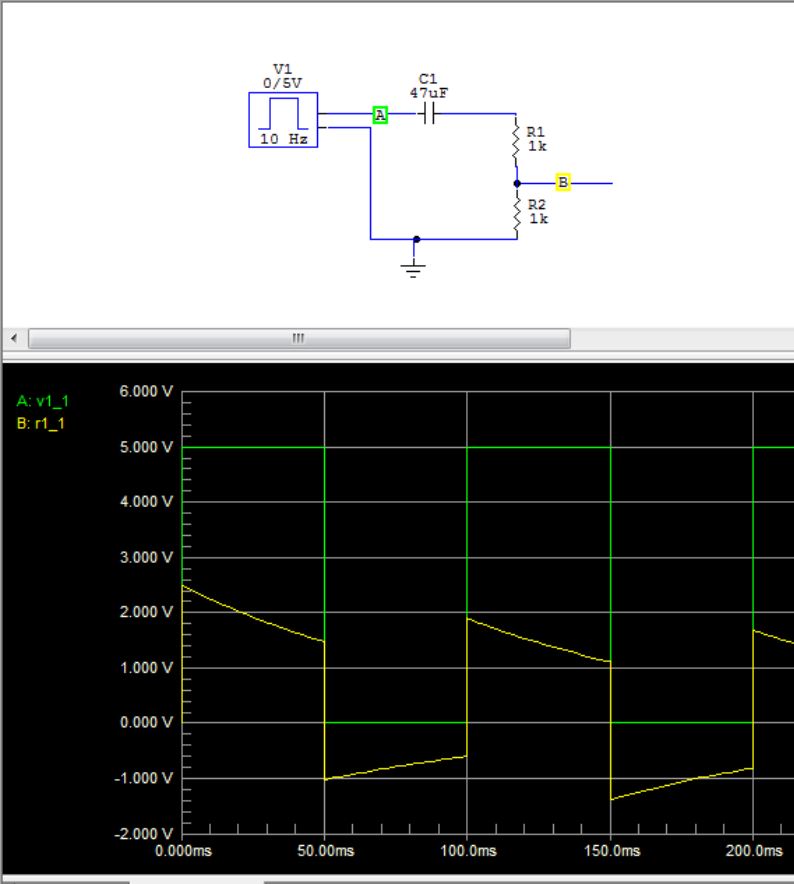
- RC_derivation.JPG (64.51 KiB) Viewed 855 times
These little PT8211s are genius!
[ahull – Fri Nov 24, 2017 5:03 pm] –
I suspect his is your issue, that capacitor/resistor combination is going to act as an R/C filter, and is going to have a negative effect
[Pito – Fri Nov 24, 2017 6:29 pm] –
With input signal as below the RC will “round the edges”, while the CR will pass the fast changes (edges) better and will suppress slow changing parts of the signal.
Hey Pito – Nice circuit diagrams and output and explanations! Cool!
Thanks, Chap – I get it. A bit of school-boy error in the readings really.
I’m confident the circuit and code are working correctly. I need to read the output on a DC coupled device.
[ahull – Fri Nov 24, 2017 5:14 pm] –
.. or you could build the pig-o-scope and use that to measure the waveformsit has no filtering or buffering whatsoever.
Wow! Thanks for the pointer – I just ordered one of the 2.4″ displays for around 4 UKP and another Blue Pill.
Another future project!
Ken
Excellent post..
Re your code.
You don’t need to use PROGMEM or the function to read it, The memory space is flat an flash and RAM addresses can be accessed directly via pointers
Just define your arrays as const , is enough to put them in flash ..
Analog read is slow for compatibility with AVR which has dedicated analog input pins and hence no need to set the pin mode
STM32is different as pins have multiple uses, so If I remember right, analogRead calls pinmode
There is direct call on the LibMaple internal API to read the analog input, but you will need to look in the core as I can’t remember off the top of my head what it’s called. You will also need t call pinMode in setup
I think there are potentially speed improvements in a few places where calculations split onto 2 lines can be combined, but I am typing this post on my IPad and it’s hard to cut and paste which lines I mean
phaseAccumulator1++; // Move to next samples position
phaseAccumulator2++;
if (phaseAccumulator1 >= maxSamples1) phaseAccumulator1 = 0; // Check for overflow i.e. value of 1024 at max freq
if (phaseAccumulator2 >= maxSamples2) phaseAccumulator2 = 0;
Thanks for the additions – Yes, I understand.
I’m coming from an AVR background, so not fully conversant with how these new 32 bit devices run.
Bizarrely, I noticed that grabbing a 16-bit sample from the wavetable in flash memory (Sine for example) was a fraction slower than doing one or two 32-bit maths functions to generate the waveform (as in Saw and Reverse Saw) – This was surprising. There was only a fraction of speed increase in it (like going from 440Hz to 450Hz on a free-running oscillator in the main loop, not using interrupts), but a speed increase none-the-less.
There was a similar tiny increase changing ‘Switch/Case’ to ‘If/Thens/Else’ in the section for calculation of the waveforms.
Ken
Try removing the PROGMEM stuff and remove the const declaration on one of the wave tables and it should get put in RAM which will be much faster
In a timed loop, the time taken reduced from 3.20 microseconds to 3.14 microseconds.
I recently experimented with overclocking the chip to 128Mhz and changed the (SPI_CLOCK_DIV4) to (SPI_CLOCK_DIV8) to ensure that the PT8211 was running within it’s limits . . . and it all worked fine.
A test of a frequency generating loop had the frequency increase from 630Hz to over 1.1Khz just by this overclocking.
I was worried that there might be errors reading the Pots at this unguaranteed rate (ADC), but they seemed fine as well.
I’m pretty sure that the main time-hog (perhaps unavoidable) is taken by the SPI.write command which, by my calculations is taking 1.3 microseconds alone to complete.
I’m looking at getting as much speed as I can right now for one of my future goals would be to use the chip for the full range of audio frequencies with multiple waveform selection . . . right now, that’s looking quite a tall order.
Ken
So if you set the SPI frequency to 36MHz, then writing one byte should take ~0,3 µseconds.
Lower SPI clock frequency will increase the time accordingly.
The PT8211 has a maximum rated clock frequency of 20Mhz . . .. however . . . my thinking was the same as yours ![]() .
.
I changed the clock rate division for 72 / 2 (36Mhz) and it still seems to run fine.
Looks like the PT8211 (well, my chip at least) can be overclocked.
Further testing to be done for stability.
Ken
You could try bypassing these checks and just directly write to the SPI output register
Then the CPU can do something, like process or fill a buffer while the DMA sends another one on it’s own to the SPI peripheral.
So the CPU doesn’t have to sit idle waiting for the SPI transfer.
Some of these MCUs have i2s mode, and in that mode the SPI peripheral can generate the WS signal on it’s own. That’s not the case on the bluepill, but you should be able to use a timer to achieve the same.
Configure a timer to overflow at the frequency you need. Set one channel output to flip on CC match, and set the value to half the timer overflow, so there will be 1 match even per timer overflow.
Then configure the DMA channel to which that timer channel is connected (check reference manual), to do the DMA requests for the SPI peripheral. Enable DMA requests in the timer channel (not the SPI peripheral, since when to do transfers will be decided by the timer, not the SPI peripheral).
Then build your table of samples in the RAM, and fire the timer.
Each time the timer CC matches the timer count, the WS output (timer channel output) will switch to the opposed value (0 pr 1), and a new DMA request will be generated/ The DMA peripheral will load a sample from ram, load it to SPI DR register, and the SPI will send it out.
On the next CC match, the WS output will switch again, for the other channel, and the DMA will pick a new sample, and load it to DR, which will send it out.
If I have time I’ll try to write you some code later.
I had the same thought
Just setup the DMA with the wavetable buffer and configure a timer to generate interrupts to trigger the DMA at the appropriate speed.
But, I wasnt sure if it was possible or how to configure it.
I’m just hacking spi.h now.
spi_tx_reg(_currentSetting->spi_d, data); // write the data to be transmitted into the SPI_DR register (this clears the TXE flag)
I’m looking with interest at spi.dmaSend and your spi.dmaSendAsync that you developed for use with your Neopixels.
Would I need any special consideration to use those commands, please?
Even just using a none blocking DMA send for a single 16 bit of data would be useful for me.
Pehaps these commands might be a better option as I am envisaging timing issues with writing directly to the register and not checking if the data has finished being sent or that SPI is ready before going round again for another send.
At the moment, my code works on a sample-by-sample basis, with each sample calculated from the state of various things . . . sending a large block of ‘predefined’ samples to be transferred using DMA might not be possible for my project in its current form.
Ken
My approach was that the frequency was controlled by a phase accumulator variable, rather than a set frequency in which data is sent via DMA.
So (in simple terms) the data send rate is set, but the amount of samples being sent changes.
In fact, I have done just this. I have written some code for a VCO (DCO) running with multiple waveforms output up to about 12Khz and fully controllable. The problem is . . . terrible aliasing for anything above 1.2Khz caused by not being able to run at a high-enough sample rate.
Ken
I’m no expert in this, but I presume to get the best resolution on the output, you always need to run at the max sample rate and build the DMA buffer accordingly, e.g. by interpolating intermediate value between those in your wavetables
However depending on your interpolation algorithm and how many points you’d need to create, the processor speed will be the limitation.

