I think there should be one more { … } at this lines: <<#######
…
if ( (gpio_read_bit(PIN_MAP[encoderpinB[counter]].gpio_device, PIN_MAP[encoderpinB[counter]].gpio_bit) ? HIGH : LOW) != B_set[counter] )
{
B_set[counter] = !B_set[counter];
if ( B_set[counter] && !A_set[counter] )
// <###################################### {
if (millis() – encodertimer > 3)
encoderpos[counter] -= 1;
else
encoderpos[counter] -= 5;
// <######################################## }
encodertimer = millis();
}
mausi_mick
BTW.
I tried you code and it worked fine, but I found I needed to use the hardware timer for another purpose, so I found it doesnt work too bad if you simply turn on the internal pullup resistor and use a 100nF capacitor between the output of the rotary encoder and GND.
I know this isnt as good as the 2 resistors and one capacitor debounce method, but it worked OK for me.
The only drawback with this simple method (using attachinterrupt on input A), is that if you turn really quickly, it looses some steps and you don’t get the 5x acceleration. But I could add acceleration by getting the millis in the interrupt handler and if it was less than some small value, since the last interrupt, then I could add or subtract 5 instead of 1.
But I do like the external analog debounce method.
I used your “sketch” with my rotary encoder that named “ROTARY ENCODER TYPE: LPD3806-600BM-G5-24C” and it works fine on the first sight.
But after couple of turns it starts to miss impulses (app. 10 impulses at one turn) When I delete a part of code for the second encoder, it starts work better and it misses only 5 impulses at one turn.
When I used quadrature encoder at the Arduino Due, all was fine. Could you explain, how I can get a valid number of impulses on the STM32duino?
(I have STM32f103c8t6)
Sorry for bad English. I am from Russia)
.. 600 pulses/revolution for a single phase.. – when using it as an manual input you can easily do 1-2rev per second. That is 600-1200 pulses/sec single phase (and it gives probably more in the quadrature mode). The routine uses millis() for the measurements – so to overload the sw could be easy then.. Try to use micros() instead. Also you may try to decrease the
#define ENCODER_RATE 1000 // in microseconds; As long as you use hardware debounce, e.g an internal pullup resistor and a small capacitor from the encoder output to gnd, this worked well.
But if you rotate quickly, it still misses steps because of the debounce time.
I tuned the capacitor value for my particular encoder, as it only seemed to need 50nF with the internal 22k pullup.
But even then, I could make it loose steps, so one approach to hiding this, is to increase the amount that you change the position variable if you detect the encoder is being rotated quickly.
The typical bounce of a microswitch takes <1ms, so the RC value seems to be ok.
I think a processing of every pulse should be possible with a 72MHz arm
I tried a few capacitors starting much higher but I didn’t have anything less than 50nF in my box of spares (well I had some 22pf etc but they were much too low)
I agree perhaps 10nF would be OK.
My “ENCODER RATE” value changed to 1. Because with the value “1000” it loses very many impulses.
I just want to get direct number of impulses by STM32duino, like in this article (http://blablacode.ru/mikrokontrollery/531) It`s not in English but the code is universal. I want to get result like this:
u16 cnt = TIM3->CNT;
Delay(100);
But there are no available descriptions of translation stm32 functions to stm32duino ( in Internet) ![]()
P.S.
Transition “millis” to “micros” cannot give an effect for my device.
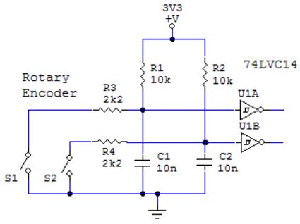
- Rotary Encoder debounce.JPG (22.62 KiB) Viewed 717 times
I work with Arduino and STM32 for about 3 month so could you explain these strings:
if ( (gpio_read_bit(PIN_MAP[encoderpinA].gpio_device, PIN_MAP[encoderpinA].gpio_bit) ? HIGH : LOW) != A_set )

{

A_set = !A_set;

if ( A_set && !B_set )

{

//if (millis() - encodertimer > 3)

encoderpos += 1;

//else

//encoderpos += 5;

}

encodertimer = micros();

}

