I have tried this simple program:
#include <STM32Sleep.h>

#include <RTClock.h>
RTClock rt(RTCSEL_LSE);
long int alarmDelay = 5;
void setup() {
// Disable ADC to save power
adc_disable_all();
// Set all GPIO pins to Analog input to save power (this disables pretty
// much all I/O incl. Serial)
setGPIOModeToAllPins(GPIO_INPUT_ANALOG);
// first a period in STOP mode, then STANDBY
sleepAndWakeUp(STOP, &rt, alarmDelay); // sleeping in stop mode for 5 seconds, then ...
sleepAndWakeUp(STANDBY, &rt, alarmDelay); // sleeping in standby mode for 5 seconds, then RESET
}
void loop() {
// We have woken up from sleep! System clock is set to 8MHz HSI.
// but never reach here
}
In the blue pill maybe you have also to consider the current drawn by the USB circuitry (pullup resistor) if powering via USB.
800uA by my back of the envelope calculation suggests a load of around 4kOhms at 3.3V
Maybe if we had a few pictures of your setup and how you are measuring, and perhaps the full schematic of the bare STM32 only board that might shed some light on the problem. I must confess that in my low power experiments when I got to sub 1mA I figured I was doing pretty well.
http://www.ti.com/lit/ds/symlink/lm741.pdf
https://en.wikipedia.org/wiki/Wheatstone_bridge
the other thing that may be tried is perhaps replace that high dropout ams1117 regulator with a ‘real’ LDO http://www.stm32duino.com/viewtopic.php … 061#p27657 & use 5000 mAH LiPo batteries, 24×365 ~ 8760 hours so i’d guess that may last say 1/2 year before needing recharge
and these days there are monster usb power banks like this 100000mAH LiPo power bank with solar cells thrown in ![]()
http://www.ebay.com/itm/New-100000mAh-D … 2162353948
I forgot to mention that I am not using any voltage regulator. The blue pill board is powered through the 3.3V pin, so only the output of the inactive regulator is seen by the power supply. The other board (custom PCB) has no regulator at all (3V non-rechargable lithium battery) and the current is exactly the same.
The schematics I am using is this:
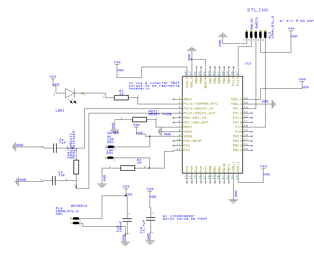
- circuit.PNG (30.89 KiB) Viewed 1188 times
..the other thing that may be tried is perhaps replace that high dropout ams1117 regulator with a ‘real’ LDO http://www.stm32duino.com/viewtopic.php … 061#p27657 & use 5000 mAH LiPo batteries, 24×365 ~ 8760 hours so i’d guess that may last say 1/2 year before needing recharge
and these days there are monster usb power banks like this 100000mAH LiPo power bank with solar cells thrown in ![]()
http://www.ebay.com/itm/New-100000mAh-D … 2162353948
the other thing would be about the clocks, i’m not too sure if simply doing stop would turn off the peripheral clocks, i’d guess one way is to stop all the APB1 and APB2 clocks as well and check power consumption
as for precise measurements, i’m thinking the inactive AMS1117 may literally be taking some power. hence for a ‘real’ test u may need to unsolder that ams1117 and put that back later ![]()
http://www.advanced-monolithic.com/pdf/ds1117.pdf
@ahull
agreed, lipo size is a trouble, that’s why all that fuss looking for a ‘real’ LDO that drop less than < 0.5v ![]()
This is strange since I expect some consumption on bluepill due to the regulator like in the Arduino Pro Mini where I have to cut the regulator trace to obtain a real low power.
the other thing would be about the clocks, i’m not too sure if simply doing stop would turn off the peripheral clocks, i’d guess one way is to stop all the APB1 and APB2 clocks as well and check power consumption
as for precise measurements, i’m thinking the inactive AMS1117 may literally be taking some power. hence for a ‘real’ test u may need to unsolder that ams1117 and put that back later ![]()
http://www.advanced-monolithic.com/pdf/ds1117.pdf
@ahull
agreed, lipo size is a trouble, that’s why all that fuss looking for a ‘real’ LDO that drop less than < 0.5v ![]()
p73 5.3.4 Stop mode
The Stop mode is based on the Cortex®-M3 deepsleep mode combined with peripheral
clock gating. The voltage regulator can be configured either in normal or low-power mode.
In Stop mode, all clocks in the 1.8 V domain are stopped, the PLL, the HSI and the HSE RC
oscillators are disabled. SRAM and register contents are preserved.
In the Stop mode, all I/O pins keep the same state as in the Run mode.
it didn’t seem to suggest that the peripheral clocks would be stopped automatically, hence you may like to try stopping the clocks
then there is also the standby mode
p75 5.3.5 Standby mode
The Standby mode allows to achieve the lowest power consumption. It is based on the
Cortex®-M3 deepsleep mode, with the voltage regulator disabled. The 1.8 V domain is
consequently powered off. The PLL, the HSI oscillator and the HSE oscillator are also
switched off. SRAM and register contents are lost except for registers in the Backup domain
and Standby circuitry (see Figure 4).
I/O states in Standby mode
In Standby mode, all I/O pins are high impedance except:
• Reset pad (still available)
• TAMPER pin if configured for tamper or calibration out
• WKUP pin, if enabled
hence you may like to try standby mode as well
oh and use a *real* LiPo LDO that drop out less than < 0.5v if you need that (e.g. running on 4.2v), that 1 Amp ams1117 is apparently not to reduce power more than its cost effectiveness regulating 5v to 3.3v and gives 1 A output reducing complaints about insufficient power. who knows someone may use blue pill to drive their 3d printer hot end ![]()
just 2 cents, hope it helps
the other thing would be about the clocks, i’m not too sure if simply doing stop would turn off the peripheral clocks, i’d guess one way is to stop all the APB1 and APB2 clocks as well and check power consumption
as for precise measurements, i’m thinking the inactive AMS1117 may literally be taking some power. hence for a ‘real’ test u may need to unsolder that ams1117 and put that back later ![]()
http://www.advanced-monolithic.com/pdf/ds1117.pdf
@ahull
agreed, lipo size is a trouble, that’s why all that fuss looking for a ‘real’ LDO that drop less than < 0.5v ![]()
The library has a function for disabling the clocks, I did not see it called when entering any mode. I think you are supposed to call it in your code if you want to stop the clock to all peripherals.
I may have missed the call to that function, if so, please let me know.
another way though in the STOP mode, you may try to put all the pins that you don’t use (e.g. the led pin) into tristate mode or even all of them into tristate mode (depending on the context)
pinMode(pin, INPUT_FLOATING);
If you use cheap off brand “Chinesium” cells, your on your own.
Are you sure there is nothing else that may be draining some of that current, and also that whatever you use to measure the current is completely accurate?
EDIT:
And out of curiosity I checked a couple other power modes. Sleep mode with HSI at 8Mhz is 800uA. I suspect the library may be getting you in SLEEP mode rather than STOP mode.
https://github.com/rogerclarkmelbourne/ … /systick.c
http://docs.leaflabs.com/static.leaflab … le-systick
runs every millisecond, it does something ‘important’, it updates the systick_uptime_millis system uptime counter;
this is where millis() and micros() provides values from.
hence the processor may be actually awake as “wfi” (wait for interrupt) and “wfe” (wait for event) would wakeup with the systick interrupt.
hence to conserve power it may be necessary to
1) configure the systick interrupt to a lower priority so that “wfi” or “wfe” won’t wake it up
or
2) systick_disable();
there’s also something from usb side which i’m not too familar if usb fires interrupts. i think usb do have a ‘start of frame’ interrupt that fires every millisecond. but i’m not sure if it sof interrupt is enabled or say disconnecting usb would stop that
the systick interrupt mainly updates systick_uptime_millis
https://github.com/rogerclarkmelbourne/ … tick.c#L84
i think this is used by the functions millis(), micros(), and you may be caught off guard but delay() uses millis()
so if you have codes that do
delay(100) //delay 100ms

