I’ve noticed that RedBear labs have an Arduino core for this chip
https://github.com/RedBearLab/nRF51822-Arduino
This includes a bootloader.
I have not done any investigation on this at all yet, but I am interested in BLE as I have some commercial work that uses BLE devices, but at the moment its limited to using preloaded firmware on the BLE boards that uses AT commands, or using interpreted basic on the BLE modules
However using Arduino to compile for the nRF51822 would be interesting to see.
Edit, its unclear if it relies on specific Red Bear board hardware
I suspect not really
I tried couple of things on my cheap Chinese NRF51822 modules after I saw your post. I’m able to use these boards with mbed sdk and they are working great by the way.
RBL boards has another Freescale MCU on them to maintain SWD-USB interface and they are using custom bootloader instead of Nordic’s OTA bootloader. This makes things a little bit complicated. I wanted to try OTA first, so I loaded RedBear bootloader to the chip using jtag without a problem and connected a led on Pin13. Led is blinking fast and when I check Nordic toolbox app on iPhone, looks like it’s already in DFU mode. But I can’t connect to it. Nordic’s documents clearly tells which pin you should pull down to put the device in DFU mode, if you are using official OTA bootloader. Tried that, didn’t work. Here’s the complicated part. RBL says you should just press the reset button, and it will wait for connection for 5 seconds in DFU mode. But reset button is not connected to NRF, It’s connected to the Freescale MCU. So I think they have created their own Reset/DFU scenario in the bootloader. By the way blinking led looks like missing a step once in 4 seconds so I think its resets itself. That’s why I couldn’t connect to it, I guess.
Then I tried to load blink example to the application region on the NRF, using jtag, without touching RBL bootloader and BTstack. It didn’t work either, same result. Looks like it stuck in some sort of DFU-Reset loop. I tried a different power supply, nothing changed.
I’m kind of new to all these and I’m out of ideas. If you want me to try anything else, just let me know.
Sorry your posts were blocked.
Its an Anti spam thing in Off Topic, as most spam comes in that way .
Anyway, it should be OK now. PM me if its not. (PS I am Admin )
Anyway. Back to your question..
I think I made it work but I need to double check.
I flashed RBL’s bootloader onto the module using an STLink adaptor (I have for STM processors) and using OpenOCD
Once I’d flashed the bootloader, I scanned using an iPhone using an app called LightBlue and it found a DFU device advertising on BLE. I think as the rest of the flash was empty, the bootload just stayed in DFU mode.
There is probably an Adroid App that does the same thing, I just happen to have the iPhone app no an iPhone I use for BLE testing.
Anyway, I installed the nRFToolbox on an Android device, and followed the instructions from RBL about OTA uploading.
I had to connect my Android device to my PC to copy the Hex file generated by the IDE, and after it was uploaded by the phone to the module, the DFU went away, and I was able to see a UART device from the nRFToolbox – as I had compiled the UART example from RBL (installed when you install the RBL Arduino core)
So I thought perhaps I can upload direct using STLink (JTAG), rather than using this complicated DFU method.
So I looked in the linker file and I can see the offset for the code is. See line 5
https://github.com/RedBearLab/nRF51822- … RF51822.ld
MEMORY

{

FLASH (rx) : ORIGIN = 0x0001C000, LENGTH = 0x24000

RAM (rwx) : ORIGIN = 0x20002800, LENGTH = 0x1800

}
I’m not sure if the freescale chip uploads via SWD or whether this is something handled internally by the bootloader. I just using the freescale chip to convert the incoming serial to SWD it would make the bootloader smaller, but in which case, I’m not sure a bootloader would be needed at all.
However using a whole freescale chip just to determine whether the IDE wants to flash the device seems like overkill.
Looking at the bootloader, I think it has a nordic soft device at the start of the file.
As I can find many matches for this soft device in the hex
https://developer.mbed.org/users/mbed_o … device.hex
But they may be using a different soft device.
Anyway, at a rough guess the actual bootloader code is probably 15k of the 60k of the total bootloader (soft device looks like it is about 45k – but this is a educated guess)
I’d say 15k is enough to implement both the DFU and serial upload types, as the STM32 bootloader including the USB libs is around 8k, and only does DFU.
So…
Where does this leave us.
Well, if we need a device to mimic the freescale chip, a Black Magic Probe seems the best solution, as this can be flashed onto a $5 STM32 board and provides both SWD and also USB to serial
I plugged in a USB to Serial adaptor and set that as the com port for uploads, compiled for upload.
Interesting thing is that they appear to use AVRDude as the programming tool
C:\Program Files (x86)\Arduino\hardware\tools\avr/bin/avrdude -CC:\Users\me\AppData\Roaming\Arduino15\packages\RedBearLab\hardware\nRF51822\1.0.0/avrdude_conf/avrdude.conf -v -v -v -v -pcortex-m0 -cavr109 -PCOM16 -b115200 -D -Uflash:w:C:\Users\me\AppData\Local\Temp\build5507143968402139026.tmp/sketch_oct30a.cpp.hex:i
So. I suspect that the freescale processor is behaving as if its the bootloader in an AVR Arduino to fool the normal AVRDude uploader into thinking its uploading to a normal AVR board.
I guess this saved RBL from having to write and compile upload tools for all platforms, as well as writing code for the bootloader and the freescale chip
Finally I’m able to put apps using OTA. The problem was my Iphone i guess but iPad did the trick. You have 5 seconds to connect and press upload or it drops the connection. It goes OTA mode for 5 seconds, then app starts, whenever I reset it. If there is no app in it, DFU-Reset loop starts as you mentioned.
The problem is, if I load the app to the app region using jtag, it’s starting to make DFU-Reset loop thing again and i can’t get out of it. DFU still works and I can upload files. Which means, I’m not corrupting Softdevice or bootloader, I guess. At the RBL forum, they say it happens when you corrupt or erase Freescale chip.
Nordic says;
Note that if you program a DFU bootloader on the device, you must use this bootloader to install the application. Programming the application with other tools will not update the bootloader settings, which means that the application might not start. Erase the device if you do not want to use the DFU bootloader anymore.
I think this is the case and they overcome this situation by using Freescale chip somehow.
Now the good news. Since they have merged Softdevice and bootloader in one file. I loaded merged file to the chip and read back just the softdevice and load it back without bootloader. And loaded just the RBLController app to the app region. It worked!!! It gets better. There is Nordic’s example for OTA bootloader on s130. There is also a Serial DFU bootloader example. I will try to make it work and maybe merge serial bootloader with s130 softdevice.
From the Nordic’s SDK documentation;
The DFU Bootloader is capable of receiving an application image on the UART and updating the current running application on the nRF51822 chip. If no application image is present in the Code Region 1 of the nRF51822 flash area, the DFU Bootloader will listen on the UART for an application image.
That’s exactly what we want. Heres the softdevice file btw. It should work with official s130 but there are different versions. I didn’t want to risk it.
I’m using Nordic’s tools with Segger j-link BTW. nRFgo Studio(programmer) recognizes chip model and it’s region limits then compares with the file you want to load. There are 3 different NRF chips. If you are using AA variant like me, according to NRFgo Studio, your offset values seems OK for flash. I can’t see Ram values.
Re:RBL bootloader
Yes. I just looked at the Hex file that i flashed to the module, and it looked like the first 40k was a soft device. I presumed that their bootloader could would need all the BLE functions, so its similar to statically linking a BLE lib with user code.
However I could not determine which soft device version they used.
I read some information on the Nordic website, and it said the Softdevice size and hence application offset changes depending on what soft device you use, so the linker setting most match the Softdevice.
In this case RBL use 0x0001C000 offset, so this may be a clue to which soft device they used.
But as you managed to extract the softdevice (only) from the bootloader data, We can use this until we know which softdevice they actually used.
Perhaps at some point we can use another softdevice if necessary, but would need to change the linker settings in the Arduino files.
Re:uploading using JTAG.
I have a JLink clone, but I dont like it. I think it does not output 3.3v.
So I am using my STLink adaptor, and it works fine with OpenOCD.
But perhaps I should solder a 3.3V regulator to my module, so I can try the Jlink with the Nordic software rather than using OpenOCD.
In the longer term however I think OpenOCD will be better, as @rickkimball, already wrote the commands to upload to STM32 using OpenOCD, directly from inside the IDE.
Anyway.
If I erase all the flash
Flash the softdevice you posted.
then flash a blink sketch hex file ( made by the Arduino IDE)
Should I be able to see a led flash If I attach one to pin P0.00 ?
I flashed the S130 hex you posted
Compiled a blink sketch flashing pin 4
I used my multimeter to look at the voltages on the pins and a pin with no name on it was flashing.
But I worked out its pin P0.21
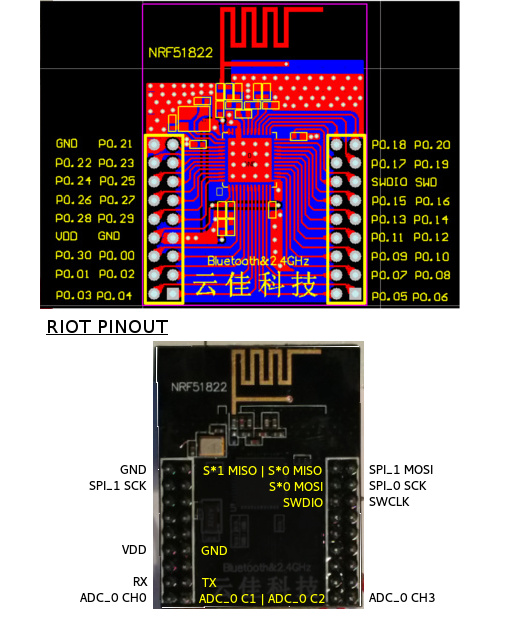
Ignore the stuff about RIOT, I just took the image from their wiki
So the RBL stuff has some bizarre pin mapping to suit their hardware.
Its in pin_transform.cpp
This is a pain, so I’m thinking of forking their repo and ripping out the pin transform stuff, so that the real pin names can be used
Anyway. At least GPIO is working, so I’d like to try to get Serial working next
However this code doesnt compile
void setup() {

// put your setup code here, to run once:

Serial.begin(115200);

Serial.println("Hello world");

}
I found this on mbed
https://developer.mbed.org/forum/team-6 … pic/17027/
It looks like the Arduino linker settings are definiatly set for the S130 soft device
However it also looks like if we change these (and perhaps some other stuff in the build) we could use the S110 instead which is smaller and takes 2k less ram
Just a few more bits of information.
I’m not sure why, but I’m finding it unreliable to just upload the sketch hex file. It seems to be better if I use mergehex (the nordic tool) to merge the sketch hex with the softdevice hex before I upload – but the problem may be my STLink debugger and your JLink may be better.
Strangely, sometimes when I try to merge, I was getting an error like this
ERROR: The hex files cannot be merged since there are conflicts.
With the help of Rick, we have modified the Black Magic Probe (BMP) firmware so that it works with the nRF51822 modules that I bought from eBay.
The problem was that the modules have the nRF51822 QFAC, which has 32kb RAM and returns a different deviceID when queried by the BMP, so that the original firmware did not recognise the device as a nRF51 and fell back to treating it as a ARM Cortex-M0
The problem with this, is that it wasnt possible to erase the whole flash or even to flash any code to the chip at all.
GDB didn’t give any errors to suggest that Flashing had not occurred, but when I tried to run the code, the old code was still there.
Anyway, with the updated version of the BMP, everything now works fine!
I can directly compile and upload from inside the IDE. All you need to do is select the COM port of the BMP’s GDB port. Note this is a little confusing, as the BMP shows up as 2 Serial devices. One of these is the Serial passthrough port, which I have connected to the Serial TX and RX on my module, the other serial device is the one that needs to be selected, as the IDE uses it to tell GDB which port to with over.
This is a little messy, It may be possible to fix this by writing a plugin for the IDE but I’m not entirely sure of (a) how to do this, and (b) what plugins are capable of doing…
One minor annoyance that still remains is that it takes ages to build.
It takes my moderately fast Core i5 machine over 40 seconds to build a blank sketch, and the IDE does not seem to cache any of the object files, so if you make a minor change and rebuild, it takes over 40 seconds again.
Looking at the build process, it creates a library called core.a from the core files e.g. WString.c but it seems to build this every single time.
So there must be something in the build recipies that is causing it to do this unnecessarily.
But at least it now works
It looks like the modules are sold (and possibly made by WaveShare) and they have a lot of information on their wiki about both the RF module and the motherboard
Items in WaveShare’s shop
http://www.waveshare.com/catalogsearch/ … q=nrf51822
Wiki for the Motherboard http://www.waveshare.com/wiki/NRF51822_ … 2_Software
Wiki for the RF module http://www.waveshare.com/wiki/Core51822
Schematic for the motherboard is here http://www.waveshare.com/w/upload/1/1b/ … ematic.pdf
Schematic for the RF module is here http://www.waveshare.com/w/upload/5/57/ … ematic.pdf
It looks like the nordic SDK files they use are from mbed
https://mbed.arm.com/teams/Nordic-Semic … 3d5/source
Commits look really up to date, in fact some only got changed a few days ago, so I think this must be compatible with version 9 of the actual nordic SDK.
I have been using V9 of the S130 soft device and it seemed to work fine, with the core.
The downside of RBL using the mbed files is that there is only code for the S130 SoftDevice, which is the larger more full featured of the S100 series.
ideally people should be given the option of using the S110 as it takes 2k less ram, which could be a big deal if they have a 16k RAM rather than 32K ram version of the nRF51822
But I don’t know anything about the way mbed is run and who maintains this stuff.
https://www.youtube.com/watch?v=WmCmqN2 … e=youtu.be
I will need to write a complete list of instructions, as I had to gloss over the setup stuff, as the limited version of the screen recorder I’m using, cuts off after 10 mins, and to be honest, I think 10 mins is perfectly long enough for a single video ![]()
Nordic provide precompiled firmware called a Softdevice, which handles all the low level hardware control and Bluetooth protocol stacks, but its not an RTOS like the ESP8266 uses.
There are different Softdevices, depending on how much functionality you need from the Bluetooth. There are 3 different Softdevices for the nRF51822, called the S110,S120 and S130.
The current code from RedBearLab only supports the S130, which is the most full featured version, but takes 2K more ram to run than the S110. (from what I’ve read).
These Softdevices are not linked like a library, you flash them like a bootloader, and they run when the device starts up. However they don’t do much in their startup code, they just do a small amount of pre-initialisation and then call main() in the users code.
The sketch has to call into the Softdevice to initialise it fully and start it working.
After that, the loop() in the sketch seems to need to call ble.waitforevent();
It is possible to run an RTOS, I know several RTOSs were being ported to this platform.
However this is not a high performance device. Ram is only 16k in the base model nRF51822 and I think the Softdevice takes half of that.
Its also not a fast device, as its generally clocked at 16MHz.
But its designed for low power applications, and I think it does them very well.
If you want a new chip to play with this winter; you could do worse than buying a few of those eBay modules, as I’ve seen them as cheap as around $6 on ebay.
The only annoying thing is the physical pin arrangement on the module.
So if you are willing to splash some more cash, those motherboards would make the assembly process a lot neater.
Actually, I’m seriously considering designing a motherboard with a STM32F103 on it to act as the BMP. But I’m not sure when I’d have time to do it ![]()
I will post my modified core on github, when i have tidied it up a bit, and If anyone wants a “warts and all” version I will zip it up and stick it on one of my virtual servers.
To make things easier…
Rick and I have thought about doing a build of the BMP that runs on Maple mini hardware.
But I also want to have the Maple mini code run like a sketch, i.e have the bootloader run the BMP.
This should not be that hard to achieve, as we just need to move the vector table offsets up a bit, and also tell the linker that it sits at 0x8005000 rather than 0x800000, then you should be able to flash the BMP into a Maple mini over DFU and still be able to get back to running sketches (albeit you’d need to put it into perpetual bootloader to do so)
I’ve just pushed the updated to the original RebBearLabs repo to my github account.
https://github.com/rogerclarkmelbourne/nRF51822-Arduino
Note. I’ve not touched their structure, so you’d need to download the zip and then copy out the RBL folder from inside arduino-1.6.x/hardware into your hardware folder
Nordic provide precompiled firmware called a Softdevice, which handles all the low level hardware control and Bluetooth protocol stacks, but its not an RTOS like the ESP8266 uses.
There are different Softdevices, depending on how much functionality you need from the Bluetooth. There are 3 different Softdevices for the nRF51822, called the S110,S120 and S130.
The current code from RedBearLab only supports the S130, which is the most full featured version, but takes 2K more ram to run than the S110. (from what I’ve read).
<..>
If you want a new chip to play with this winter; you could do worse than buying a few of those eBay modules, as I’ve seen them as cheap as around $6 on ebay.
<…>
No worries
I want to make the installation process a lot simpler than it was for me. So I agree its best to hold off until Rick and I have ironed out all the creases.
I think Rick has some of the modules on order, and has also ordered the motherboard, in fact he may have ordered a motherboard including the RF module.
Probably getting the BMP working with the Maple Mini and retaining the bootloader is the next thing I need to do.
But also there is a minor annoyance in that on power on the BMP halts the processor.
So I think I need to modify the BMP so that it doesn’t do this.
Increasing the build speed is also something that needs to be sorted out.
There is something a bit strange about the build recipes , which are causing this, and also I cant change the build recipes to make it worth with 1.6.6 as it no longer links.
Apart from the large number of include paths they use, I can’t quite see why I can’t just re-purpose our recipes (or perhaps I can !)
Anyway… Watch this space
So I think I need to modify the BMP so that it doesn’t do this.
My version of the RBL version is now here
https://github.com/rogerclarkmelbourne/nRF51822-Arduino
Note its the S130 branch
This is a link to the Nordic product selector matrix for the nRF51
http://www.nordicsemi.com/eng/content/d … x_v2.1.pdf
It shows the part number, Hardware ID and RAM and Flash size.
I think the current nRF51.c file in the BMP is not totally correct, in terms of both flash size and RAM size, as it sets virtually all variants to 256k flash and 16k RAM.
If I get time I’ll fix this
I thought I’d post an update to my issue with the board not running on powerup.
I found this posting on the Nordic site
https://devzone.nordicsemi.com/question … ble-reset/
As far as I can tell, they are implying that the SDIO line also acts as a reset. This seems to be corroborated looking at the schematic for the Waveshare “motherboard” which appears to have a push button that connects SDIO to GND, and as far as I can tell, looking at the picture of the board, the button is labelled “Reset”
So..
The strange thing, is Why am I the only one who has this problem when using the Black Magic Probe, as the normal init code in the BMP drives both SDIO and SCK low in platform.c init()
Perhaps most ARM boards don’t care the default state of SDIO but it appears that the nRF51 does care and it needs to be high
Edit.
I also found this which states the SWDIO line doubles up as the reset line
I’m not precisely sure what happened to get my nRf51 board into this configuration, but I ended up needing to manually use monitor erase_mass before I could get it working again.
I’d been experimenting with various things.. 3 different BMP boards, (a GD32 board, a Red Pill STM32f103C8 and a Maple mini STM32f103CB)
And I had also tried flashing some precompiled firmware to make the nRF51 into a BLE packet sniffer.
Anyway, Uploads from the IDE seemed to hang and code would not get uploaded and run.
I tried manually uploading the code and manually replacing the S130 Softdevice, but to no avail.
i tried flashing RBL’s bootloader hex, which I know instantly should appear as a DFU device on BLE, and that did not work either.
So I used monitor erase_mass to clear the whole MCU, re uploaded the RBL bootloader, and immediately, the DFU device appeared on BLE.
So I reflashed the S130 Softdevice, and uploaded Blink again, and all was right with the world.
So the moral of the story….
If things stop working and don’t make any sense… Erase the whole device, and reinstate the S130 Softdevice.
http://www.rogerclark.net/arduino-on-th … ontroller/
I’ve also updated my github repo for this today, by adding a new branch S130_corelib, which vastly speeds to build times, and also fixes an issue with uploads on Linux and OSX
nRF51822-Arduino/arduino-1.6.x/hardware/RBL/RBL_nRF51822/cores/RBL_nRF51822/pin_transform.cpp
Seems like you should be able to create a pin mapping without touching the core .cpp files.
-rick
I didn’t change the pin mapping because I tought the Waveshare board was basically the same as the RBL board.
But my “motherboard” has still not arrived, so it’s difficult to sort this out until it does.
From what I recall, RBLs pins for Serial are not the same as Nordic use on their evaluation board, but was the same as Waveshare. RBL used P9 and P11 but I think Nordic use either 0 and 1 or 1 and 2
I don’t especially like the way RBL coded the pin mapping in a switch statement, and like you say, it needs to be moved into the variant.
I had overlooked this when I moved all the core and variant code into the corelib, but it’s not a big deal to remove the variant code back out if there.
I was initially not intending to use a corelib.a as I had hoped to fix the issue in platform.txt which was not caching the objects, but although I found a few errors in platform.txt; fixing them did not resolve the failure to cache.
Btw.
I managed to get my JLink working with this as well, but I will need to write an upload script, as the JLink CLI needs an external command file, as it can’t be scripted using multiple arguments like gab can ![]()
1. BMP (uses Baite maple mini) works fine, no problems with flashing
2. Arduino 1.6.5 has no problems with compilation and upload (selected QFAA variant), no errors or warnings.
BUT the only thing that works is RedBearLabs bootloader- DFU device is visible.
All example sketches are not working, module does not advertise and there is no communication over serial.
I’ve searched nordicsemi.com and compatibility matrix says my IC is compatible only with s110 softdevice, how complicated would be to use it instead of s130?
and…
Did you flash the S130 soft device to the board?
Bizarrely, I think Blinky will run even if the S130 soft device is missing. ( though I could be wrong as its been a while since I remember this happening)
I have seen wierd things happen if there is a fault with the 32kHz crystal ( which is unlikely in your case)
Someone gave me some 32khz crystals to use with another mRF51822 module, and Blinky worked, but the BLE stuff was very flakey and kept immediately disconnecting.
Anyway, when I looked closely, the crystals were 38hhz not 32.768khz
I also got similar issues when using a 32khz crystal without any 12pF capacitors.
but again, I doubt thats the issue unless you have a faulty module.
Do you have a spare module that you could try, in case its one of these hardware issues.
PS. did you post a comment to my blog?
I notice there is a comment waiting for moderation, on a similar topic
Bizarrely, I think Blinky will run even if the S130 soft device is missing. ( though I could be wrong as its been a while since I remember this happening)
I have seen wierd things happen if there is a fault with the 32kHz crystal ( which is unlikely in your case)
Someone gave me some 32khz crystals to use with another mRF51822 module, and Blinky worked, but the BLE stuff was very flakey and kept immediately disconnecting.
Anyway, when I looked closely, the crystals were 38hhz not 32.768khz
I also got similar issues when using a 32khz crystal without any 12pF capacitors.
but again, I doubt thats the issue unless you have a faulty module.
The BMP upload only flashes the App bit
I think mbed combines the softdevice with the code, which makes it much bigger.
(Nordic also do this in their examples, I think they use some code called MergeHex (or something like that))
But there is no need to replace the whole lot each time.
I wonder if its the SoftDevice version. I know that Nordic released newer versions of the S130 a month two ago.
I’ve attached the SoftDevice that I was using.
Re: Blog
No. Someone else seems to have some upload issues. Not sure what it is, the BMP seems to hang. Possibly a device ID issue (no idea at the moment really)
But the upload script in platform.txt doesn’t use erase mass, I think it uses load file (sorry i cant remember the exact syntax)
Re:RBL
they just upload the app via the co processor or via BLE DFU ( their bootloader includes BLE DFU, however I found it a pain to upload as I had transfer to an android device and them use a Nordic test app to upload via BLE DFU, its much easier via BMP or JLink)
I’ve successfully (I think) made the Maple mini into a BMP.
Just stuck on GDB/ softdevice:
COM ports are recognised in Windows Device Manager as:
COM3 ( Silicon Labs CP210x USB to UART Bridge)
COM4 (Black Magic GDB Server)
COM5 (Black Magic UART Port)
GDB only recognises COM3. For COM4 it returns: ” \.\com4: No such file or directory”. Same with COM5.
Trying COM3 (out of interest) returns:”
Remote debugging using \\.\com3
Ignoring packet error, continuing…
warning: unrecognized item “timeout” in “qSupp
Ignoring packet error, continuing…
Remote replied unexpectedly to ‘vMustReplyEmpt
“monitor” command not supported by this target
Don’t know how to attach. Try “help target”.
”
Before trying the softdevice step (in Roger’s guide on his blog), I tried to upload a Blink sketch from Arduino IDE. I managed to get the console to return:
“Target voltage not Implemented!
Available targets:
No. Att Driver
1 Nordic nRF51 0x0084”
Obviously, it didn’t upload at all but that’s as far as I’ve gotten.
Since then whenever I try to upload the sketch, the Arduino IDE just stays at halfway through upload showing errors in the console.
I’ve set everything up on Windows 8.1 , but am very comfortable in Linux/ Shell if it’s easier/more likely to work.
I think my wiring is correct:
NRF51 slotted into motherboard.
Motherboard connected to Maple Mini (tried switching the SWD SWIO wires multiple times just in case,to no avail).
USB from pc to motherboard for power.
USB from pc to Maple Mini.
I don’t have the UART connected to the Mini (although I think I did try, to no avail).
My QF version is ACA1.
Hopefully my NRF51 is not dead.
Thanks,
Avi
Nordic nRF51 0x0084
As it gets the chip ID from the nRF51 and checks it against a list to display that message
Remote debugging using \\.\com3
Ignoring packet error, continuing…
is strange
I’ve not seen that before
You could try contacting Gareth (who writes the BMP) via gitter or via a github issue (I think gitter is the best place to start as its less formal than posting a issue for this question)
I should point out that GDB never read:
Nordic nRF51 0x0084
That only appeared once, ever, in the Arduino IDE terminal output when I tried uploading a sketch, before I’d installed GDB properly (I think it
was on my system before from Android Studio/Eclipse or one of the many suites installed…). Arduino IDE probably uses GDB in some way anyway (?).
Could it be that
Remote debugging using \\.\com3
Ignoring packet error, continuing…
is appearing because COM3 is not the GDB server (COM4 is) ?
Was thinking of starting procedure again from scratch as last resort.
Cheers for the support as always.
I use the command written my Rick Kimball ( on this site) for the STM32 upload using GDB.
Its just the commands to connect and scan and uoload, rolled into a single command line.
You should not see errors when you run the target extended remote.
I would also try a different usb port or a shorter cable in this case
i got mesmerised by your video on youtube on nRF51822 ![]()
https://www.youtube.com/watch?v=WmCmqN2i_Xo
& took the bait & ordered this
http://www.ebay.com/itm/201652571766
the competition of making nRF51822 boards seemed to be heating up
if the search is made for nrf51822 on ebay, low prices actually hit usd3.50 ea, i chose the above as it has more of the gpio pins broken out
http://www.ebay.com/sch/i.html?_from=R4 … 22&_sop=15
some of these are apparently from co Wireless-Tag, the great thing is that the board specs are rather well published on the page
http://www.wireless-tag.com/index.php/p … is/26.html
http://www.wireless-tag.com/index.php/p … is/25.html
i’d guess we’d soon need to add this as a ‘board’ in its own ‘sub board forum’ never mind it is not stm32 it is cortex-m & pretty much open platform ![]()
it seemed st is trying to make something similar with stm32 hopefully that’d reach mass mkt soon
blinky now goes BLE ![]()
http://www.st.com/en/wireless-connectiv … tId=SC1898
http://www.st.com/content/st_com/en/pro … nrg-1.html
hopefully we could get those boards soon in mass market too
for now st seem to have this dev board for BlueNRG at a pretty hefty price tag though, hopefully the ‘nucleo’ & common dev board versions would be out soon ![]()
http://www.st.com/content/st_com/en/pro … 007v1.html
oops/oh found another, the ‘nucleo’ board with BlueNRG
http://www.st.com/content/st_com/en/pro … b04a1.html
it seemed BLE is cooking up a storm as BLE connects to any android phones/devices > 4.3, recent iphones & windows > 8
Those boards are made by Wireless-tag.
I have some of the larger ones, but they were more expensive when I bought them last year.
The one thing they lack is the 32khz crystal oscillator which means they do not keep time very well when sleeping.
Initially the repo I used / modified from RBL didnt work with them because it needed the 32 khz crystal, but my newer repo ( also a hacked version of RBLs) does now support them.
But I now recommend that people use Sandeep’s repo as its much better than the RBL one.
What I think will also increase the use of BLE is the Web BLE API that Google have added to Chrome in the last month.
On Android it needs Marshmallow ( Android 6) and none of my devices currently have this, but over time most users will have this and be able to simply write HTML and Javascript to interact with their BLE devices.
At the moment I am using Cordova to write my Android apps, and it works fine and is very simple to install and use, even on windows.
e.g. I just plug jn my phone , goto the directory with the project files in it and type “cordova run android” and a few seconds later the changes I made to the app have been compiled and the app is running on my Android phone.
I am currently designing a new bluetooth board , which will use the new nordic chip , the nRF52840, which will have a similar form factor to the Blue Pill.
The nRF52840 is 64MHz cortex M4F and has 256k RAM and 1M flash, and supports BLE 5 including the long range / high power transmission modes.
Unfortunately the nRF52840 wont be available in commercial quantities until Q4 this year. But thats only 6 months away and ai have a lot of design and prototyping before then ![]()
https://zpcat.blogspot.sg/2013/10/how-b … layer.html
– scanning
– standby
– advertising
– initiating
– connection
full Bluetooth specs:
https://www.bluetooth.com/specification … ifications
https://www.bluetooth.org/DocMan/handle … _id=286439
————–
however the truth is that there are many other protocol stack layers on top of this BLE link layer
e.g. L2CAP (this manages the ‘connections’ and multiplexing to the various endpoints e.g. ATT/GATT, service discovery etc
GAP, service discovery, security (e.g. paring / autentication and encryption negotiation), ATT, GATT (services) themselves etc
while i’ve not gone further, my guess is that these mcu (and the vendor distributed protocol stack) with such extreme limited ram memory e.g. 8k, 16k, 20k most likely only make do with the only basic BLE ‘link layer’ (i.e. the above states) and leaving aside all other protocol stack layers e.g. L2CAP, GAP, etc
this could literally mean that for a lot of BLE devices implemented on such low resources devices possibly make do with little or no security (e.g. no pairing, no encryption (or propriety encryption) etc. i’d think some actual device developers simply ‘hard code’ the PIN ![]() lol
lol
I have had to decline to work for several companies, as they did not take security seriously, and it would come back to bite me as I am an independent contractor, and these sorts of companies tend to blame everyone else for their problems.
I would not worry about the internals of bluetooth. It just works, and can be secure if you use the API correctly.
The nRF51822QFAA and QFAB versions only have 16k RAM but are still relatively secure in terms of comms
The Nordic “Softdevice”, which handles the BLE takes about 8k of RAM, and around 128k of flash code space.
Luckily flash is now cheap, so using the QFAA varient, which has 256k flash, still leaves loads of application space, though having only 8k of remaining RAM for the application code, can be restructive.
The QFAC version has 32k RAM, and the newer generation nRF52832 has loads of Ram ( I think it may be 256k)
I am currently using the nRF51 in legacy designs, but will move to the nRF52 for new designs, especially the new nRF52840 which is BLE 5 compliant
i think some of the developers resort to pairing ‘when nobody else is around’ methodology that would at least ensure some kind of security as a compromise, sometimes known as ‘just works’ pairing, but i’d think that may add the need for a ‘hard’ reset button ![]()

