Please, help me with advise.
I’m building incubator and I’m looking for proper techniques for keeping certain temperature.
Currently what I’ve found is:
- Hysteresis
Pros : Easy to write the code
Cons : Not very precise and has wide distribution
- PID
Pros: Kept temperature is much closer to targeted
Cons: A bit harder to program (but I’ve found the library for that)
When I assembled everything together, the initial heating time was very long (but it also may be caused by volume of my incubator).
The question is :
Is it reasonable to make something like a hybrid temperature control “Hysteresis + PID”.
Example: if target temperature range inside of incubator 37 ± 2 °C (but closer to 37 is better), split control into 3 “phases”:
1) below lower limit (< 35°C) : turn the heater constantly ON
2) Inside of allowed range (35 … 39 °C) : use PID
3) above allowed range : turn off the heater and turn on the ventilation (cooling with air from around the incubator)
Thanks!
The calculation is incredibly simple (Pseudocode is on wikipedia), and I find the Arduino library for PID made a load of assumptions about AVR hardware which were not correct.
The Arduino PID library assumes you are reading via analog input and controlling via analog output, which was not appropriate in my case and my not be for yours.
IMHO, you need to take some readings on the response times of your incubator and build a model inside a spreadsheet
e.g. how many degrees per minute does the temperature change when heat is applied
How quickly does your sensor detect the changes, and what resolution is your temperature sensor
Re: Hysteresis
You can build this into PID, so its not an Either/Or between PID and non PID
Other thoughts
You may want to consider doing some sort of PWM on the heater
If you use a SSR you can turn the heater on and off many times per second.
Or you may want to simulate various levels of power (over a longer period e.g. 10 seconds) but taking the output of your PID and feeding it into something that converts proportion of power e.g 0.000 to 1.000 into PWM e.g. power of 0.1 could be on for 1 sec, then off for 10 secs
Or perhaps on for 0.5 secs then off for 4.5 secs
I suspect it would be easier to get the PID working if you had some system like that.
[RogerClark – Tue Mar 27, 2018 3:29 am] –
The calculation is incredibly simple (Pseudocode is on wikipedia)
Yes, I’ve seen it, but I don’t understand how to adjust Kd, Ki and Kd constants.
[RogerClark – Tue Mar 27, 2018 3:29 am] –
The Arduino PID library assumes you are reading via analog input and controlling via analog output…
Actually, it’s not so. Here is the guy, how used this library with MCP9808 and TMP102 sensors, and made it works (sorry, video is in Russian language):
https://www.youtube.com/watch?v=9odcsuAquLU&t
Library : https://github.com/br3ttb/Arduino-PID-Library/
[RogerClark – Tue Mar 27, 2018 3:29 am] –
You may want to consider doing some sort of PWM on the heater
If you use a SSR you can turn the heater on and off many times per second.
Yes, I’m going to use the SSR module to control the heater. Heater is going to be a 95W heating lamp (not sure if it will be enough for incubator 27*57*24 inch, probably, I would need to install 2 of them).
Would you suggest to use PWM with this module https://www.ebay.com/itm/DC-5V-4-Channe … SwtS1ZpTGu ? Or just turn it on/off many times per second?
Thanks!
I wrote the different variables into columns in excel and then wrote some simple calculations for each cell and then dragged the cells down to replicate them
I set the 3 constant (k) values by guessing what would work, in my case its mainly Ki of 0.005 and not much in Kp or Kd but your system will be different
There are probably other and better ways to do this.
Re: SSR
You you can’t achieve a “dimming” effect using a SSR as its not designed to work like a triac or fet based controller, as there will be problems with synchronisation with the mains frequency as SSR’s often only turn on during zero crossing (though yours may be different)
For my system I built my own triac power board, but that is not necessary for you.
You could try changing the PWM period to perhaps 10 seconds and control the value so that the minimum ON time is 0.25 seconds, as that would give you 40 steps of power
But it depends on the latency / inertia of your “system” e.g. mass of the box etc and time to heat etc etc
In a previous job, I used to work on outdoor signs with hundreds of incandescent lamps in the days before LEDs were commonly available. The triac controllers in those signs never quite turned the lamps completely off. They would phase back to about 10% so the filaments were always warm. That extended the bulb life quite a bit. The bulbs were krypton filled and would extinguish almost immediately when power was removed.
I worry that constantly turning your heat lamp on and off, may cause it to have a shorter life.
Thanks for the link to the Triac module. I think although it says 5A, you’d need to put a heat sink onto that triac, as I use 60A triacs on a heat sink and they get warm on a 2kW load.
Also, its interesting that you never totally turn the lamps off.
In my case, buy the “4000W” dimmer modules from AliExpress etc, and remove the triac and the heat sink and some other components and solder them onto my own PCBs.
As its cheaper to do that than to buy the triac and heat sink separately.
I’m pretty sure I posted the code I use for my dimmer, as the STM32 has a fantastic built in system called One Pulse, where all you need to do is setup the timer config registers to trigger from an external source and set the delay and pulse width and the delayed pulse to fire the triac happens without the need for a ISR etc
All you need to is change the timer Overflow and Compare registers when you want to change the delay
Works like a charm!
[fredbox – Wed Mar 28, 2018 2:02 am] –
If you want to be able to do phase control, you will need to use a triac with the drive waveform triggered from zero crossing. There are inexpensive triac modules available – https://www.aliexpress.com/store/produc … 142eHxhSst but you would still need a zero crossing pulse for triggering
So, for purpose of dimming is it better to use module with Zero-Cross detector like this one http://robotdyn.com/ac-light-dimmer-mod … -110v.html ?
Or even make something based on following schematics:
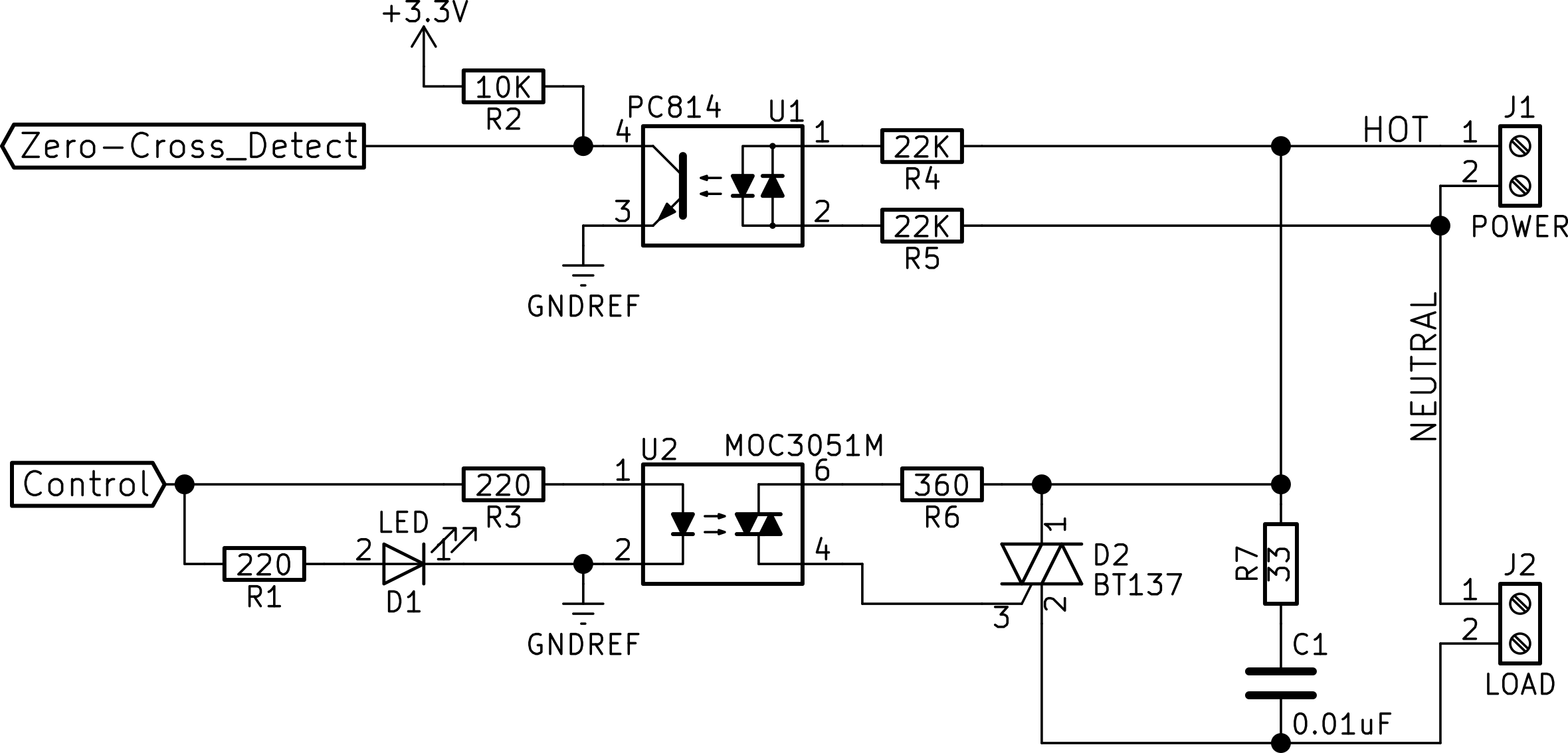
- g5593.png (141.39 KiB) Viewed 440 times
Hysteresis was configured thanks a potentiometer.
The main things is to have a good temperature sensor with a good accuracy (<0.5°). I’ve used the SI7021 which also measure humidity.
I had to drive humidity control so hysteresis was sufficient to balance between temp/hum.
For fun, I’ve used embedded wizard to make the gui.
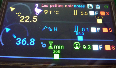
- goose.png (179.21 KiB) Viewed 440 times
So you will need larger than normal resistors. (probably 2W)
Also the reason that the circuit uses 2 x 22k resistors is that most resistors are not rated for use above around 100V, so even 2 resistors is not ideal, and 3 or 4 resistors are better.
[fpiSTM – Wed Mar 28, 2018 5:13 am] –
I helped my brother-in-law to make a goose incubator, I used hysteresis method and that’s enough.
Hysteresis was configured thanks a potentiometer.The main things is to have a good temperature sensor with a good accuracy (<0.5°). I’ve used the SI7021 which also measure humidity.
I had to drive humidity control so hysteresis was sufficient to balance between temp/hum.
For fun, I’ve used embedded wizard to make the gui.
goose.png
Looks very professional
[RogerClark – Wed Mar 28, 2018 7:31 am] –
Looks very professional
But it is not ![]() At least it is functional, He succeed to breed geese
At least it is functional, He succeed to breed geese ![]()
[fpiSTM – Wed Mar 28, 2018 5:13 am] –
I helped my brother-in-law to make a goose incubator, I used hysteresis method and that’s enough.
Hysteresis was configured thanks a potentiometer.The main things is to have a good temperature sensor with a good accuracy (<0.5°). I’ve used the SI7021 which also measure humidity.
I had to drive humidity control so hysteresis was sufficient to balance between temp/hum.
For fun, I’ve used embedded wizard to make the gui.
goose.png
Thanks, that’s good to know.
But how close to the target temperature is temperature inside?
I was thinking to use the MCP9808 for temperature sensing.
P.S. It is for BMP (bio-methane potential) testing, so humidity is not a parameter needed to be monitored in my case)
Accuracy:
– ±0.25 (typical) from -40°C to +125°C
– ±0.5°C (maximum) from -20°C to 100°C
– ±1°C (maximum) from -40°C to +125°C
• User-Selectable Measurement Resolution:
– +0.5°C, +0.25°C, +0.125°C, +0.0625°C
Temperature inside is also mainly depending of the heating capacity, the heating volume, air circuit (fan?).
We made several tests and logged all measurements on a SD to draw the curves thanks excel. (response time, maintain the temperature,…)
At the end we are on average +/-0.2°C around the order even with the atomizer in action.
I don’t know BMP, so it mainly depends on your constraints.
Modules are available starting from 3,5€: https://www.aliexpress.com/item/DC-3V-5 … 49117.html
Useful read: https://electronics.stackexchange.com/q … rtd-probes
I found an incredible project for egg incubator with humidity control and even with system for shot eggs and much more, the tutorials The author is often concerned with temperature control etc … everything related to your research is here. Happy reading.
[moc – Wed Mar 28, 2018 9:39 pm] –
I have used the MAX31865 (via SPI) with a good PT100 probe in a project and was blown away by the speed and accuracy.
Modules are available starting from 3,5€: https://www.aliexpress.com/item/DC-3V-5 … 49117.html
Useful read: https://electronics.stackexchange.com/q … rtd-probes
I’ve just received couple of those. Thanks for pointing that.
