Its a very long story, going back many months, but I have a lot of problems with the cheap Chinese made T-962 reflow oven.
I will post the full story when I get time, but as an update to my latest experiments and deductions…
I removed both thermocouples from there normal location(s) in the oven, and taped them to a piece of blank PCB using Kapton tape ( no I didnt shirt them to the PCB ![]()
I ran a test ramp, actually full power to a set temperature (220deg) and recorded the temperature via the serial output ( i’m using the Unified Engineering replacement firmware, which has logging via serial)
I then plotted the log in Excel, and worked out that one thermocouple reads 9% higher than the other.
But apart from that, the temperature curve for both thermocouples was very similar.
I thought I could correct this difference, by changing the thermcouple gain setting, as the replacement firmware has offset and gain controls in it.
However when I tried changing the gain and offset, it made no difference.
Looking at the source code, for the firmware, I realised that the gain and offset settings are only applies to the analogue ADC thermocouple inputs, and not the digital inputs using the Max31855 (that I am using)
So I have now modified the firmware, so that the digital inputs can also have the settings applied to them.
But I have not had time to reflash the firmware. Hopefully I will have tme to do it tomorrow.
I did try telling the oven to heat to 220 deg, and put various blobs of solder paste on a scrap piece of pcb, but its barely melting, right in the middle of the oven.
So i think one TC must be reading high rather than the other one reading low.
Incidently, i have 4 TCs and have compared the readings on all of then, and no 2 TCs give the same readings, or anywhere close to being the same.
If they are within 10% of each other at 200 deg, its a miracle.
But it doesnt matter too much, as long as I can eventually get both TCs to read the same values, as I can also calibrate them against the melting point of my solder paste, which according to the data sheet should start to melt at around 180deg.
So the oven is barely getting 180 deg at the moment, when I tell it to heat to 220.
As the firmware has preset reflow profiles, I definitely need to calibrTe the TCs or it will be impossiblr to use the presets.
Anyway, I will keep you guys posted on any progress I make
http://www.instructables.com/id/T962A-S … /?ALLSTEPS
this guy seems to have the same problem. He modded the fan in the back.
I wander why this owen doesn’t have a fan like cheap cooking owens.
About TC different reading. I am not a TC expert but I know that they give a weak signal that must be amplified and is easy to have noise. But they must give the same signal.
Are you sure that they are TC and not a more common NTC?
Edit:here
http://hackaday.com/2014/11/27/improvin … flow-oven/
they talk about TC and col junction so they must be TC and not NTC!
The firmware by Unified Engineering (on gitHub) pulses the cooking fan, (in the back of the oven), in an attempt to agitate the air inside the oven, and this causes some air to be blown out the vents during the bake part of the reflow, not just the cooking stage (which is what the main fan is really there to do)
The problem I’m having is that no 2 thermocouples reads the same values when the temperature that is being measured is 200deg C or more.
I have a multimeter with thermocouple input (its sold for this purpose) and I tried 4 different thermocouples, bought from eBay, and they all read different values when the oven is supposed to be 200 deg. The range is quite large (190 to 210 deg) i.e around +/- 5 deg.
I guess the thermocouples I bought could all be complete junk. I could buy some TC’s from a local supplier, but they look exactly the same as the ones from eBay, and I feel, I’d be paying 10 times as much and getting the same product
I think I need to do some more research on TC’s as they are not supposed to have this much variance.
Most information seems to suggest that K type thermocouples have an absolute accuracy of +/- 2 deg or 0.75% whichever is the greatest.
So even at 200deg, the differences between these should be less than 2 deg.
But thats not what I’m seeing.
I’m using these MAX31855 modules from eBay
http://www.ebay.com.au/itm/MAX31855K-Th … SwUV9WmIZG
and thermocouples like this one
http://www.ebay.com.au/itm/100cm-1M-Wir … SwHaBWhj5A
I’m not sure if I’m supposed to do this, but I take the plugs apart, and untwist the wires from around the pins, and then put the wires straight into the connector block of the MAX31855 modules
I’m not sure if there is a problem with doing this, i.e if the plugs are made of some sort of special metal.
anyway, readings are fine at room temperature etc, just go wildly off as things get really hot ![]()
http://www.ni.com/white-paper/7108/it/
a white paper by National Instruments about error sources using thermocouples.
Re: possible problems
I have not extended the wires. luckily they are long enough to reach to the control board.
All I did was to take the 2 pin plugs apart, unwrap the single core metal wires from around the screws in the plug, where they were attached to the pins, and then i screwed those wires straight into the connector block on the Max31855K modules.
I did put Kapton tape around the end of the wire that goes inside the oven, which would be making contact with the metal wires ( but not covering the TC junction).
I thought Kapton tape was a good insulator, and it would not effect the readings, but perhaps this is the problem.
But, I probably wont get time to look at this again in detail until the weekend, as work is too busy at the moment.
I may try ordering some more thermocouples, from a different supplier on eBay, as I think this batch came from the same supplier and may all be cheap knock-offs
Re:Max31855K
Its possible these are not genuine.
But with the changes Ive made to the firmware in the oven, I can apply a offset and gain correction to the incoming data, so I should be able to get the readings for the two TCs to be close enough to reality for the oven to work.
I taped all three thermocouples within 3cm of each other, put them in the reflow oven, and ran the oven in an override program which just turns the heaters on (and it also uses the cooling fan to agitate the air a bit). I then stopped the override program, which turns on the cooling fan, before turning the oven off completely.
But I get the same sort of results I get when using 2 random themocouples connected to the reflow oven’s controller.
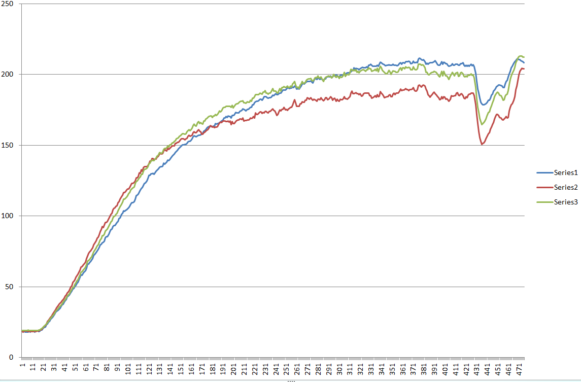
- three_new_thermocouples.png (52.79 KiB) Viewed 1837 times
I swapped the first 2 thermcouples, and it appears that one the problem has moved, but its not totally conclusive, as the 2 “good” thermocouples are no longer tracking together as they are not on the same 2 MAX31855’s as before.
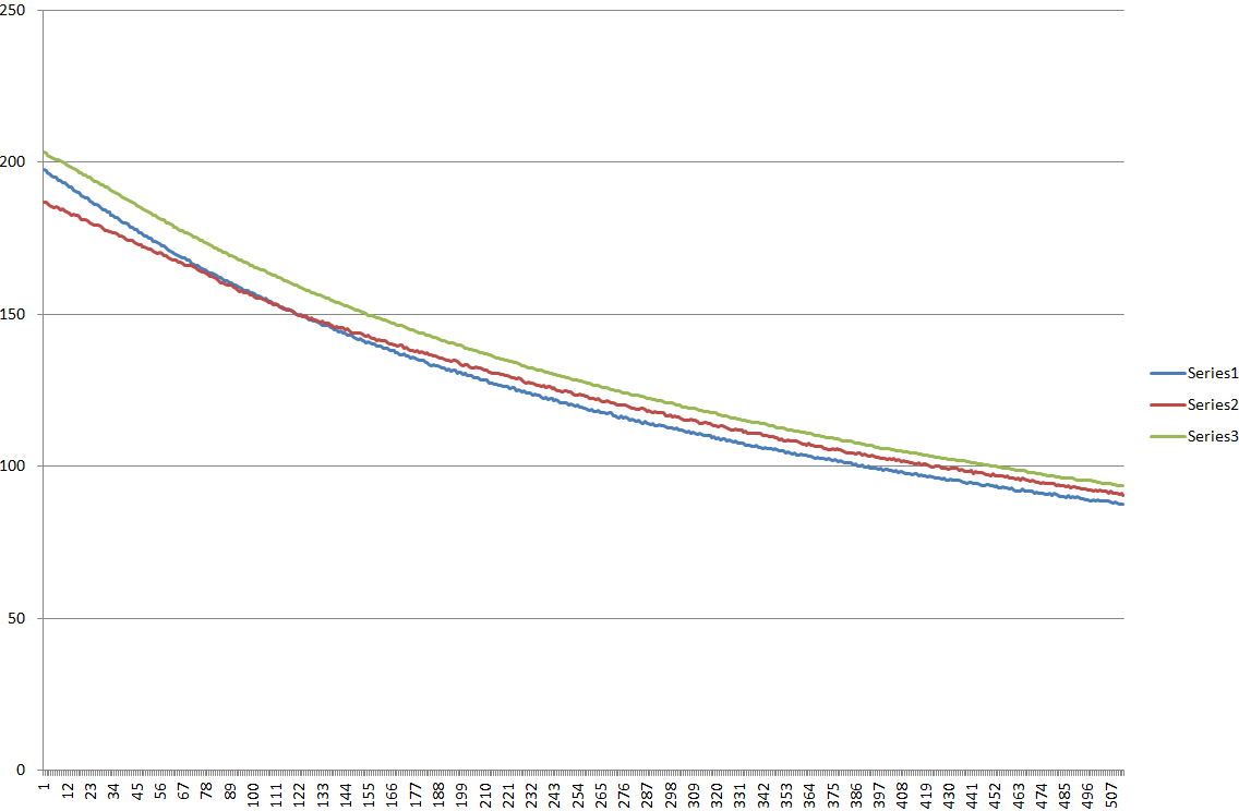
- swapped_thermouple_one_and_two.png (25.74 KiB) Viewed 1835 times
It doesn’t work for a couple of reasons…
(1) It contains 2 constructors, one to use hardware SPI and one that uses Software SPI (built into the lib).
The software SPI constructor has arguments names MISO,
Adafruit_MAX31855::Adafruit_MAX31855(int8_t SCLK, int8_t _CS, int8_t MISO) {
I must say that I am perplexed as your experience does not come close to tracking my previous use case: EFT for a Rotax engine on an experimental aircraft. My design used two channels on the Mega2560.
From the ASM International White Paper:
WHITE PAPER
How to Prevent Temperature Measurement Errors When Installing Thermocouple Sensors and Transmitters
__________________________________________________________________________________________
– 3 –
While you can form a thermocouple simply by combining two dissimilar metal conductors, a number of standard
thermocouple types are available that utilize specific metals and alloys, combined to produce larger, more stable,
and predictable output voltages with respect to applied thermal gradients. These standard types are referenced
to a cold-junction at 0°C, and their thermoelectric voltages at specific temperatures are tabulated in their standard
thermocouple tables relative to 0.000mV at 0°C. Note that these thermocouple voltages could have been
referenced to any temperature, like a room temperature of 25°C, but 0°C was chosen because it’s easily
reproducible to within ±0.2°C using a mixture or slurry of ice and water. Thus, if you hold the cold junction at 0°C,
your measured voltage will directly correspond to the thermoelectric voltage contribution of the hot junction
temperature and this temperature can be easily found via look up in the standard table for the particular
thermocouple type.
My experience with MAX13855 suggests an excellent match with 2 professional EGT thermocouples from eBay. I used the ice-bath, ambient temp, and boiling water (barometric adj.) Both thermocouplrs tracked.
The owner of the aircraft obtained the Max13855’s directly from the manufacturer as usability samples.
// Object / Library Instantiations

MAX31855 thermocouple_EGT1(thermoCLK, thermoCS_1, thermoDO);

MAX31855 thermocouple_EGT2(thermoCLK, thermoCS_2, thermoDO);
I will double check those definitions. I presumed as the adafruit library compiles fine on AVR and even Esp8266 that the problem must be that the core contains non-standard definitions
But I will double check what the AVR and SAM cores define.
Perhaps they define them elsewhere, to the preprocessor doesnt end up screwing up the adafruit library.
Actually, I don’t think the code in the library follows best practice. I think they used uppercase names, e.g. MISO as arguments so it didnt clash with the name of the internal variable miso
However, I thought in general that upper case was used to signify macros and constants, and it would be better to use underscores in front method vars (properties) ( assuming they are private), and perhaps even use misoPin etc as the argument
Its possible that the thermocouples from eBay are complete junk.
The connectors have “K” written on them. So they are supposed to be K type.
The Max31855 are also K type
I think most people would not notice the errors, as I doubt to many people use 3 thermocouples in close proximity at the same time, to measure temperatures in excess of 200 deg C
In the 0 to 100 deg range, most of them are fairly OK.
I did remove the plugs and so I could screw the wires directly into the terminal blocks on the Max31855 modules, but that the only thing I have changed.
I have 2 ,more unopened thermocouples in the pack of 5 and a DMM that has thermocouple input. So I may try comparing its readings with the Arduino / Max31855 readings
But its all very perplexing at the moment
It looks like the SAM core doesnt use a macro it uses a static var
static const uint8_t SS   = BOARD_SPI_SS0;

static const uint8_t SS1  = BOARD_SPI_SS1;

static const uint8_t SS2  = BOARD_SPI_SS2;

static const uint8_t SS3  = BOARD_SPI_SS3;

static const uint8_t MOSI = PIN_SPI_MOSI;

static const uint8_t MISO = PIN_SPI_MISO;

static const uint8_t SCK  = PIN_SPI_SCK;


