I have some cortex-m0 MCU’s (Nordic nrf51822), and I was hoping to flash them with a J-Link clone board programmer, however I have a feeling that the programmer only supports the high end ARM cores and not the simple ones
I did try to connect it to an STM32 ages ago, but got nowhere, so I presume that it doesnt support M3 either
I don’t suppose there is any way to use a STLink as a generic SWD programming tool is there, e.g. using OpenOCD ??
http://redbearlab.com/nrf51822-sdk/
link at the bottom to an app note
https://www.nordicsemi.com/eng/nordic/d … 7/79799228
this one wants you to login
according to the hardware archive files, 23 & 24 on the chip(??) are swdio and swclk, and if i read the circuit correctly they’re separate to the main connector 31 pins? references P0.00 – P0.30
srp
As its an ARM device it will have SWC and SWD line, like the STM32 has.
But it seems to matter what “Cortex” is inside the device.
The STM32F103 are Cortex-m3, where as the Nordic part I’m trying to flash is Cortex-M0
I don’t think STLink will work with the Nordic part, even thought it has SWC and SWD lines, as the STLink software will not understand the architecture of the M0
So I think I need to buy another SWD programming tool, but I’m not sure what.
I think I need to contact @rickkimbal about this, as I see he has done a posting about something similar on his blog
https://github.com/RickKimball/blackmag … rc/nrf51.c
Seems like openocd also has support for the nrf51 with an st-link as the debugger.
https://devzone.nordicsemi.com/question … d-openocd/
-rick
Sorry. I PM’ed you and then noticed you’d replied
I’ll checkout those links
Thanks
Roger
Update.
I think I think my best option is going to be to Flash BMP onto a F103C8 (or I may also try flashing it onto GD32F103C8 – as I have more of them)
I’ll let you know how I get on
Thanks
Roger
$ arm-none-eabi-gdb -ex 'target extended-remote /dev/ttyACM0' -ex 'mon swdp_scan' -ex 'attach 1' build/blinky.elf

GNU gdb (GNU Tools for ARM Embedded Processors) 7.6.0.20140731-cvs

Copyright (C) 2013 Free Software Foundation, Inc.

License GPLv3+: GNU GPL version 3 or later <http://gnu.org/licenses/gpl.html>

This is free software: you are free to change and redistribute it.

There is NO WARRANTY, to the extent permitted by law.  Type "show copying"

and "show warranty" for details.

This GDB was configured as "--host=i686-linux-gnu --target=arm-none-eabi".

For bug reporting instructions, please see:

<http://www.gnu.org/software/gdb/bugs/>...

Reading symbols from /home/kimballr/github/lpc8xx/build/blinky.elf...done.

Remote debugging using /dev/ttyACM0

Target voltage: Not Implemented!

Available Targets:

No. Att Driver

1      LPC8xx

Attaching to program: /home/kimballr/github/lpc8xx/build/blinky.elf, Remote target

delay_ms (ms=ms@entry=450) at main.c:29

29	    	asm("nop");

(gdb) load

Loading section .text, size 0x1e0 lma 0x0

Start address 0xca, load size 480

Transfer rate: 2 KB/sec, 480 bytes/write.

(gdb) b main

Breakpoint 1 at 0x16a: file main.c, line 36.

(gdb) r

The program being debugged has been started already.

Start it from the beginning? (y or n) y
Starting program: /home/kimballr/github/lpc8xx/build/blinky.elf
Note: automatically using hardware breakpoints for read-only addresses.
Breakpoint 1, main () at main.c:36
36 LPC_FLASHCTRL->FLASHCFG &= ~(0b11); // configure flash for 0 wait state
(gdb)
(gdb) n
37 SysTick_Config(12000000 / 1000); // 12Mhz / 1000
(gdb) n
39 LPC_GPIO_PORT->DIR0 |= LED_MASK; // set pin as output
(gdb) c
Continuing.
^C
Program received signal SIGINT, Interrupt.
delay_ms (ms=ms@entry=450) at main.c:29
29 asm("nop");
I’ve not had time to wire up my Cortex-M0 MCU yet, but I hope to do it today.
In the longer term, I have also been looking at better ways to flash the Xtensa based ESP8266, and I think the BMP may also be a possibility.
However Im not sure if the guys at esp8266.com have ironed out using OpenOCD with the ESP8266 yet.
-rick
I bought 2 of them a month or two ago, but have not had time to even power them up.
I dont know if they come pre-flashed with anything at all.
I guess I should at least try supplying one of them with power, and see if anything shows up on a BLE scanner app on my old iPhone.
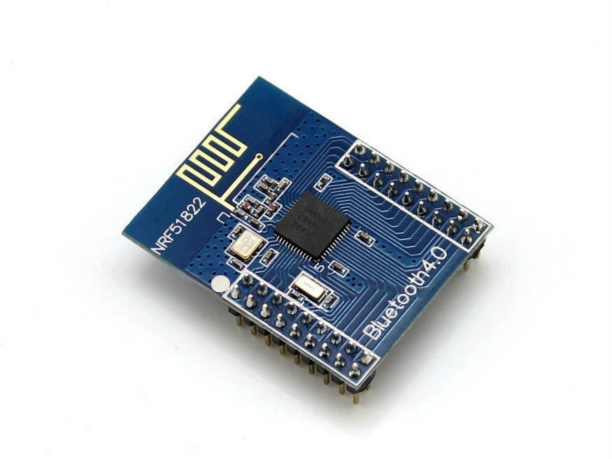
Those nRF51822 modules don’t have pin headers which are the same distance apart as I normal.
each row of pins seems to be 2mm apart, rather than the normal 2.5mm (0.1in)
Also the pins are not as long as on the Maple mini etc, and appear to be a bit skinnier.
So what I did was solder individual pins on the top to provide power etc
I’ve seen a “Mother board” for this module on eBay and AliExpress for around $15, but its mainly just a bunch of headers, though it also includes a USB to Serial chip, which I presume is wired to 2 of the pins on the header for the nRF51822 module.
Actually looking at the pinout in the spec, I can’t see any pins being dedicated to the UART, so perhaps its configurable which pins the UART uses (but don’t quote me on that)
BTW. I tried powering it, but I think the modules are blank and not flashed with the Nordic demo firmware. i.e I tried running the Nordic demo iPhone app, but it couldn’t find anything.
I can use a normal STLink adapter as a debugger with the nRF51822 using OpenOCD
The Stlink attaches OK, but the status at the moment is when I try to flash a hex file to the board, OpenOCD doesnt give me any feedback, so I suspect its not actually doing anything
BTW.
I’m compiling using Eclipse (Kepler), and I seem to be able to generate hex and bin files, but as those files are BLE examples, they don’t seem to do anything useful like blink and LED so that I know for sure they are running
I suspect I’ll need to adapt the BLE example that seems to compile, and get it to flash a LED on a gpio pin, just so I know the flashing to the device has worked (which I don’t think is happening at the moment)
I got a bit further.
I found the reason I could not seem to flash the device, was that telnetting into openocd (127.0.0.1 4444), and using the flash write_image erase xxx.bin 0 didn’t seem to like the path to the file
I tried a full windows path, with back slashes (as is the norm for Windows) but it didnt work.
So I move the bin file to the folder where openocd was run from i.e where the exe is (as I found by typing pwd that its default path was where its exe was)
Then just re-issued the command
flash write_image erase PATH-TO-YOUR-BINARY/YOUR-BINARY.bin 0
More progress – well kind of…
I found that RedBear labs have an Arduino core, and a bootloader
I flashed their bootloader hex file from
https://github.com/RedBearLab/nRF51822- … loader.hex
and the device now appears on BLE as a DFU device !!
I’m not entirely sure how to upload from windows to a BLE DFU device, but at least I know know that flashing works, but my code build appears not to.
I think I’ve flashed a program compiled in the Arduino IDE using DFU from my Android phone to the nRF51822
using https://github.com/RedBearLab/nRF51822-Arduino
Its kind of hard to tell, because the sketch appears to tell the BLE to “advertise” using a nordic specific code that my general BLE scanner does not see
However if I compile the UART example from the RedBearLab example and flash via my phone via DFU, then if I run the Nordic toobox app on my phone, it appears to see and connect to the BLE Uart device
However the Nordic app isnt very useful at doing this, as it doesnt seem to have a way to type commands to the DFU device, but perhaps I can find another app that is compatible with the Nordic uart BLE device profile
