A while back I ordered a few “STM8S103F3P6 Minimum System Development Board”s with a clone ST-Link programmer. The ST-Link programmer was DOA, and now I can not program the STM8S boards. Instead of buying a new clone (and waiting nearly 2 months for it to arrive), I was wondering if I can build my own ST-Link clone using a STM32 Blue Pill board?
Where should I start looking?
Thank you!
I think a solution would be to build out a BMP which can provide the ST-Link functionality.
Ray
I received a “CC Debugger” from an eBay supplier and found it was totally blank. Fortunately I knew someone with another one of these and we managed to flash my CC Debugger using his CC debugger.
So this sort of thing definitely happens.
https://goo.gl/photos/bHJvb6caAPjTQW318
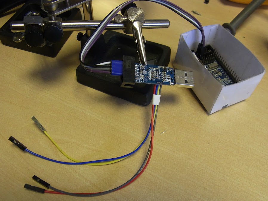
If I had it to hand, I’d tell you which pins were which, but you can probably figure it out quite easily with a multimeter.
Because STM8 uses SWIM instead STM32 uses SWD. STlinkv2 clones have two different ports, one SWIM and the other SWD.
My progress so far:
– downloaded and flashed the blackmagic.bin file in bmp_j66_coreboard_20150524.zip to a Blue Pill
– connect the ST-Link clone to the BMP
– run dfu-util -l and get: Found Runtime: [1d50:6018] ver=0100, devnum=9, cfg=1, intf=4, alt=0, name=”Black Magic Firmware Upgrade (JC66CoreBoard)”, serial=”B6CBAEDB”
– run arm-none-eabi-gdb with target extended-remote /dev/cu.usbmodemB6CBAED1, followed by monitor swdp_scan and get
Target voltage: Not Implemented!

Available Targets:

No. Att Driver

1      STM32F1 medium density
It looks like the BMP is seeing the STLink board.
There isn’t any special hardware on those STLink dongles.
I managed to flash the bootloader to one of those dongles and I think it worked fine, albeit they are of limited use, as they have hardly any gpio connections available.
That Russian site is an interesting read. (English Translation)
The Swim_RST is controlled by PB5 and PB6.
To me seems a lot of pins. I wonder why.
@Kenjutsu
you wired only these pins, with resistors R7,R8,R10,R17,R18 and two zeners VD6 and VD7?
- R1, R2 and C1 to PA0
R19 to LED1, LED2 to R20 for U1_BL_TX
R8 to PB5 & PB6 for SWIM_RST
PB7 to PB9 to PB10 to R7 for SWIM to R10 to 3V3
PB8 to PB11 to SWIM
![]()
Including a minimal schematic (without leds) of the programmer board with STM32F103C8 minimum development board.

