http://www.ebay.com/itm/M590E-GSM-GPRS- … SwYlJW6pub
Ebay sellers say it is 5V powered, but after some googling seems that the right power is from 3.6 V to 4.3 V and seems compatible with 3,3V MCUs.
Here some reference:
http://www.sunduino.pl/wordpress/gsm-m5 … -i-prosto/
http://www.radioterminal.ru/upl_instruc … s_V1.0.pdf
http://wless.ru/files/GSM/Neoway/Neoway … e_V1_0.pdf
http://www.academia.edu/15633281/GSM_GP … oway_M590E
I’ve just ordered one (not possible to resist… ![]() )
)
So if anyone is interested…
Cheers
I went for the http://www.aliexpress.com/item/Smart-El … 4074facc32
Wow… this module seems to be the best for quality/price ratio.
And is made by the ESP8266 guys… see here: http://www.myelectronicslab.com/tutoria … i-thinker/
Absolutely I’ll buy one too..!!! ![]()
PS: it seems I’ve diffused a strange sort of virus… and I’m the first victim… ![]()
I suspect most of the EU is ending it sooner.
I suspect most of the EU is ending it sooner.
I suspect most of the EU is ending it sooner.
I suspect most of the EU is ending it sooner.
I thought, IoT, generally refers to Internet connected devices, rather than something that sends texts etc via GSM
‘oh this session is all safety play and will run rather late’, i’d better delay the heating.
so if anything was sent back to the mobile in number of rings code, you’d be ejected moderately slowly
stephen
Ray
I agree.
Posts have been deleted.
Ray can you remove your quote, it propagates the information
This is somewhat off topic, even for the this thread.
I’d rather it was not discussed here at all.
I’m not suggesting you stop posting completely, but we all have to self moderate.
This is somewhat off topic, even for the this thread.
I’d rather it was not discussed here at all.
I’m not suggesting you stop posting completely, but we all have to self moderate.
… Maybe a different case than the one you are thinking, but the IT manager at the South Carolina textile plant that implemented the technique (circa 1978) lost his job, became a convicted felon, and screwed up the rest of his life for doing this stupid, stupid thing! What is so sad, the money he tried to save was not even his own. Fraud is bad business for everyone.
Ray
at&t Senior IT Enterprise Architect, retired
This device WONT BOOT unless you connect the BOOT pin. I did just route it to DTR and this works.
This device can do SMS send / receive. It can also do tcp-ip. I have no data plan and i have no idea what it costs me, but i can connect to my PC via GPRS and exchange data with a $2 phone worldwide. This did pretty much blow my mind. I did not test if DNS does work, i did connect to fixed IP, but it should work.
You need to know the IP stuff and the NAT stuff on your router to get it working. The sequence for TCP-IP is:
at+xisp=0 // interner tcpip stack verwenden

at+cgdcont=1,"ip","internet" // sunrise apn setzen

at+xiic=1 // start ppp

at+tcpsetup=0,177.194.29.176,1005 // call meine ip, port 1005

at+tcpsend=0,10 // sende 10 zeichen

// send 10 char here
Like:
1. how to wire the module (where to connect boot – we do not have dtr)
2. how to power the module
3. how to write a sketch to send a sms
4. how to write a sketch to receive a sms
5. etc..
DTR – there is no dtr on the 1.93$ module. Most probably we will run it from maple mini or such..
What is ssWrite?
1. to use power source with at least 2A current capability
2. Boot pin to Gnd
3. To replace the 4k7 resistor with a 10k (sim card signal pullup)..
The .edu source says the powering is critical – a 3.6V LiPo and 1000uF decoupling, powering on/off the module and the power source sequence is critical.
Also the voltage shall not drop below 3.3V while txing.
That would not work reliably with LiPo 3.6V and the 1N4001 diode there however, as the diode will have about 0.7V forward drop at 2A (1n4001 is 1A diode, btw).. Maybe schottky may help, or none..
I run it on a 2A 12V source with cheapo chinese step-down to 4.5V, prob 4A max. No problems.
I did sucesfully send an SMS
Setup, text mode, gsm charset
at+cmgf=1

at+cscs="GSM"
http://neo.aeris.com/
http://neo.aeris.com/pricing/plans-pricing/
Aeris has been doing low rate telemetry for a very long time.
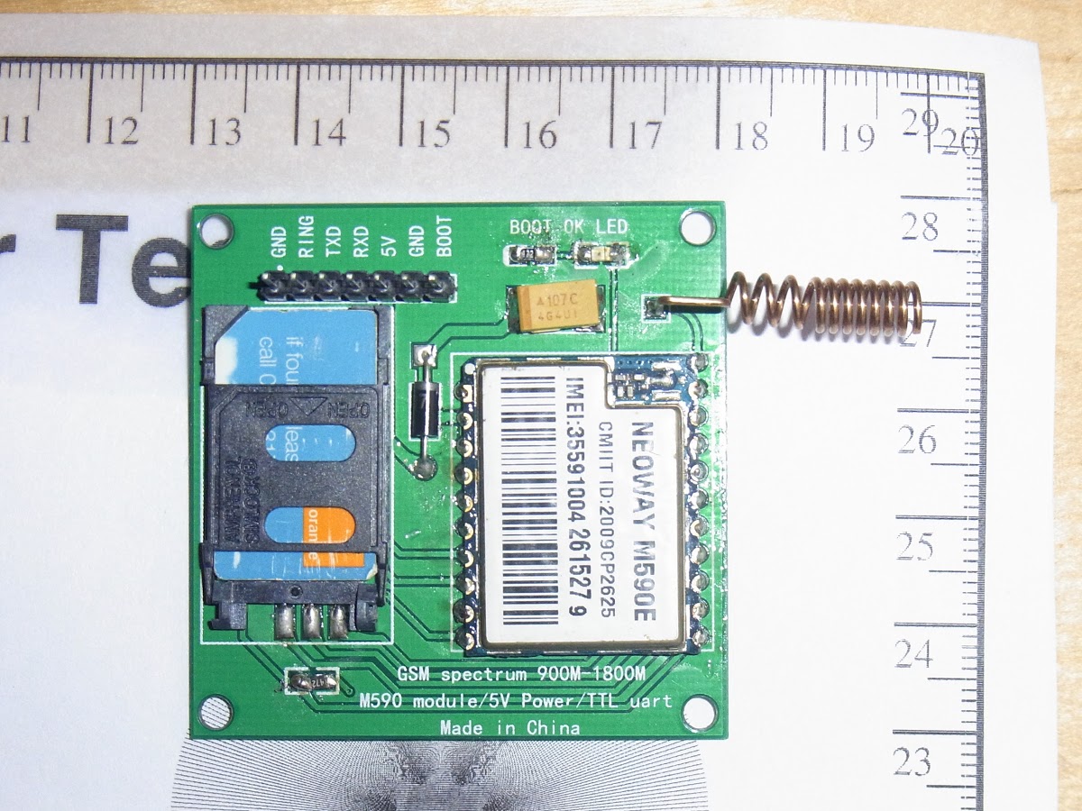
looking at the board, diode (bar) track indicate which end of the big cap is positive.
someone remind me, is the bar line on the capacitor is positive or negative?
i have this funny feeling its the negative.
stephen
looking at the board, diode (bar) track indicate which end of the big cap is positive.
someone remind me, is the bar line on the capacitor is positive or negative?
i have this funny feeling its the negative.
stephen
it would not have been funny, although i’m tempted to sacrifice one to see
srp
it would not have been funny, although i’m tempted to sacrifice one to see
srp

i suspect the module is 2mm spacing and a whole different technique.
pureed water melon – um!
6uF – excellent
i had to open the video flash frame in another window for it to play, no entry sign in the post.
stephen
They are listing at $1.55 with free P&P, almost 20% discount over $1.93 ![]()
I struggle to understand how they can pack and post anything for that.
I’m resisting until I’ve seen a bit more feedback here.
Also, I like the look of the SIM800L quad-band modules.
Insanely expensive at $4.40, but Quad-band for goodness sake ![]()
Also, I like the look of the SIM800L quad-band modules.
Insanely expensive at $4.40, but Quad-band for goodness sake ![]()
If you are thinking of using this in the UK you only need 900/1800Mhz, but beware whose SIM you use you cant use “Three” sims as they wont work even though they can fall back to 2G. There are some other networks that use the “three” network which should also be avoided.
We do try to make stuff that works in most countries, not just the UK.
The target users are schools, colleges and universities, so avoiding cost shocks is important. Hence my interest in receive only, no-top-up SIMs.
The target users are schools, colleges and universities, so avoiding cost shocks is important. Hence my interest in receive only, no-top-up SIMs.
How about robot control over SMS using the same SIMs?-) Network latency might be a problem!
Do you live in the UK? What part? I owe you a pint.
Cheers.
Now, I took better look at it. TLDR – OH MY, IT IS CRUSTY AND UGLY PIECE OF CRAP!
The modules are apparently desoldered from some GSM equipment – though listing says “New: A brand-new, unused, unopened, undamaged item in its original packaging (where packaging is applicable).”
The bottom side of module is bulged
https://picasaweb.google.com/lh/photo/4 … directlink
indication serious overheating of the PCB and its delamination. There are flux residuals
https://picasaweb.google.com/lh/photo/I … directlink
Upper side of PCB is crusty as hell, full of dust
https://picasaweb.google.com/lh/photo/W … directlink
and as you can see, the passive network around GSM RF output is damaged.
The sticker on upper side of module looks like removed or cooked during desoldering process. Bleh
https://picasaweb.google.com/lh/photo/R … directlink
second piece is somehow better, but not great at all
https://picasaweb.google.com/lh/photo/c … directlink
desoldered as well
https://picasaweb.google.com/lh/photo/c … directlink
The modules are of different revisions – 1.0 vs 1.3, not sure what differences are there. I’m pretty sure the crusty module will not work, the another one – perhaps.
I noticed the 1N4007 diodes have leads approximately 0,5mm thick. Cost cutting, here we go. The power supply is 1N4007 in series with module, decoupled with single 100uF capacitor – now this is so wrong…
Regarding the general hints for GSM modules:
– good power supply. Usually the modules expect one Li-Ion battery, so 3.6-4.2V. Voltages over 4.5V are often indicated as overvoltage and module can shut down. The same goes for undervoltage. The 1N4007 in series with 5V is joke.
– good power supply, again. Use proper decoupling, even with beefy source as Li-Ion battery. Few pieces of 100uF tantalum capacitors and one 10uF ceramics can’t hurt.
– beware of RF interference. buy a lot of RF chokes, 100pF capacitors, use at least doublesided PCB and good grounding
– Sending one SMS is simple, making good AT commands parser is nightmare.
– the modules usually do have 2,8V or 3,3V signalling voltages.
I’ve done a few GSM phones before
https://picasaweb.google.com/1118907411 … PhoneTest1
https://hackaday.io/project/558-rotary- … bile-phone
https://picasaweb.google.com/1001130002 … tK_Wi6D-fw
and except of the rotary dial phone it was one of the more complicated side of my projects.
I run both boards as delivered, no changes at all. I use the included antenna (that crappy coiled thing). I can send / receive SMS and i can get TCP-IP connections over GPRS. Surprisingly the module has BETTER reception than my smartphone (same provider, weak gsm signal).
Dont scare people off. This sub $2 things work excellently well. If you dont need audio there is no reason to get the $6 sim800l or the $20 sim900 modules.
Mine are definitely desoldered and I’m pretty sure it’s not customer return – it is obvious the modules have been sitting on dusty and moist PCB for months or years and then desoldered.
I’ll give it one more try – it seems like modules from DX are marginally cheaper and I have better experience with DX quality. I just had bad luck with this seller.
The price has been falling over the past weeks already, maybe AI Thinker are looking to corner the Wide Area Wireless hobby market like they have done with the ESP8266 in the WIFI Market. To introduce a device > $4 that is quad band and audio is no mean feat.
No prizes for the soldering I must admit ![]() , and since I couldn’t find my magnifier, or my leaded solder, or indeed my tweezer set (they are all presumably hiding in the same place), I had to use my leadfree crappy solder, two pairs of reading glasses, and a bigger tipped iron to be sure of melting the crappy solder. I’ll test it in the morning. The other two will be neater, I promise, once I find the missing tools.
, and since I couldn’t find my magnifier, or my leaded solder, or indeed my tweezer set (they are all presumably hiding in the same place), I had to use my leadfree crappy solder, two pairs of reading glasses, and a bigger tipped iron to be sure of melting the crappy solder. I’ll test it in the morning. The other two will be neater, I promise, once I find the missing tools. ![]()
EDIT: I presume I can link out that diode and run it straight from a LiPo… time will tell.. I can see at least one of these joining the magic smoke club.
Since I intend to run it from a LiPo, I don’t think this is likely to be an issue for me, but it is something to be taken in to account when connecting the thing up. I would assume 3V3 logic rather than 5V is likely to be your best bet.
Also …“VBAT (Pin2 and 3) is the main power supply of the module, with input range of 3.3V to 4.8V, with the recommended voltage of 3.9V. Maximum instantaneous current input to the module is 2A. USE HIGH VALUE, LOW ESR CAPACITORS, CLOSE TO THE MODULE. “… in other words, you can’t drive the module from a tiny little LDO voltage regulator, ‘cos it will vanish in a puff of smoke. If you use a voltage regulator it must be beefy enough to cope with 2A without complaining. Furthermore if you intend to switch the module on and off with your main MCU, to conserve battery life, you will need to use a mosfet or transistor that can switch 2A plus.
I am using mine with 3.3V logic and have no problems.
I dont know if the device tolerates 5V logic from the arduino-avr devices. Has someone tested this?
So I gave negative feedback to the eBay vendor as I can’t be bother arguing with them, and the changes are they are a fly-by-night vendor and don’t care what feedback is given.
I have not had time to solder the thing together and I will need to clean the solder blobs off the GPRS module first, otherwise its going to be hard to solder it down neatly, as there are blobs of solder on some pads but not all of them
So I gave negative feedback to the eBay vendor as I can’t be bother arguing with them, and the changes are they are a fly-by-night vendor and don’t care what feedback is given.
@ahull – maybe a little bit better antenna would help. The one there is rather a “dummy load”. There are antenna modules – $1 ceramic patch antennas, which may work even in Scottish Highlands
This would explain the large number of recovered units in the e-waste stream. This in turn suggests that the majority, if not all of these will, like the large number of “Arduino Nokia 5110 display” ebay items, come from salvage, rather than surplus stock. I have no problem with that, but may be of concern to others.
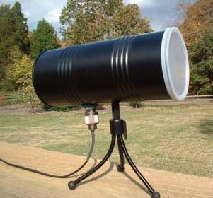
The external antenna looks to be a must. I’ll see if I can solder on an RF pigtail, and design some sort of yagi antenna. I know where the nearest cell tower is, so I have a good line of sight to it, its just rather too far for the bent paper clip that is supplied with the board.
http://www.k7mem.com/Electronic_Noteboo … i_vhf.html
Example. “The current design is an antenna for 1800.000 MHz. It has 1 Reflector, 1 Driven, and 14 Director Elements. Estimated Gain is 14.234 dBd”. … that will probably allow me to connect to the moon. ![]() the advantage of the relatively high frequency of course is that a 14 element yagi antenna is only about two feet long, and not twenty feet.
the advantage of the relatively high frequency of course is that a 14 element yagi antenna is only about two feet long, and not twenty feet.
The first one, with crusty and overheated module is dead as brick.
The second one, works, somehow. After “booting” (holding BOOT pin for a second on low level) the BOOT LED stars blinking and module accepts AT commands at 9600 baud.
All I wrote before, about need for stable and beefy power supply is still valid. The original way of generating power for module by dropping 0,7V on diode is joke (module restarted after entering PIN – due to current spikes for network registration), so I connected stable 4,0V power directly across the filtering capacitor. By the way, the diode has very thin leads, looks more like 1N4148’s leads.
Without diode it’s better, module responds at+ccid, indication SIM is wired correctly, at+cpin=”xxxx” correctly with OK and doesn’t restart, momentarily takes a lot of juice from power supply (that is expected) though any consequent operation (+cpin? +cops? +ccid) above SIM card ends up with ERROR message until I restart the module manually. Meh. Perhaps it can’t access network, it may be because of the “antenna”, which is in the same category as the power supply.
EDIT: got it working by using longer piece of wire antenna instead of original short piece of wire. One has to use proper chinese engineering when dealing with chinese devices. ![]() Sometimes I get garbled characters, though http://pastebin.com/tRxLm7YV
Sometimes I get garbled characters, though http://pastebin.com/tRxLm7YV
I think those modules could be usable with proper power supply and antenna, but that goes for all GSM modules. I like Antenova A10340 antennas https://picasaweb.google.com/1001130002 … tK_Wi6D-fw
Such combination is btw. always recommended by big players as decoupling with ie. 1000uF aluminum works maybe till 200Hz cutoff.. It will not provide enough charge with milli/useconds current pulses.. A ceramic multilayer of 10uF capacitance is a better choice (for high current, short rising edge current pulses) than the 1000uF one, sure
Such combination is btw. always recommended by big players as decoupling with ie. 1000uF aluminum works maybe till 200Hz cutoff.. It will not provide enough charge with milli/useconds current pulses.. A ceramic multilayer of 10uF capacitance is a better choice (for high current, short rising edge current pulses) than the 1000uF one, sure
I once spent a couple of months trying to figure out why one of my customer’s very expensive computers would crash randomly especially in the evening and early morning. The problem, it turned out was due to the Taxi firm operating a very large VHF transmitter in the adjacent building. We moved the computer behind a large earthed metal filing cabinet and the issue went away. History does not relate whether there were any long term health effects from being gently cooked by close proximity to the transmitter, but it certainly didn’t do the computer any good. Random crashes due to RF bleeding into your microntroller are something you might have to contend with if you don’t keep on top of the screening and decoupling.
I have solder wick etc, so it should be ok.
I just object to being miss sold.
Re:nokia displays
Yes…
Same thing.
In have received many that are scratched, or dirty, or even have burn in with an fuzzy logo.
Only half of them could be considered as vague new and possibly used in a project that I build for someone else.
After a significant troubleshooting effort they discovered a cleaning lady pulled a network component’s mains plug off while hoovering the carpet
BTW, does the stuff work with those cheapo Tesco cards? (Cheapo.. not at all .. a pity the credit is valid for 30days only and it is not transferrable ![]() )..
)..
I set-up my second “testing” SIM card from O2 in 2014 or so, made calls/sent SMS for something like 1EUR in total while testing my cellphones, now I turned it on after a year of inactivity, the number is still alive. I didn’t pay a single cent in the period of inactivity. Now I made a few calls/sent a few SMS, I expect invoice for 10 cents perhaps.
BTW, what could be done with the M590E module (I mean what kind of services/connectivity may work):
1. when I get a sim with voice only
2. when I get a sim with voice and “data” ?

- pito.jpg (2.1 KiB) Viewed 663 times
Every morning – no workie.
Every late morning – workie fine.
Eventually, I realized: Early AM, sun shined in, hit tape loop reflector sensors. Screwed up vacuum control.
Cure: Cardboard taped to drive’s plexiglass door.
I have more.
Every morning – no workie.
Every late morning – workie fine.
Eventually, I realized: Early AM, sun shined in, hit tape loop reflector sensors. Screwed up vacuum control.
Cure: Cardboard taped to drive’s plexiglass door.
I have more.
Keep them coming… this thread is already way off topic
Good idea about looking at photos of the assembled board.
I must admit, I stalled when I realised that the board doesnt have any markings to indicate capacitor polarisation.
I’d already soldered on the SM cap before I realised that it was polarised.
Luckily I think its the right way around.
The cap looks the same way around as I’ve seen it in other photos.
I will try to build my board at the weekend.
Good job I bought 2, as the SM resistors are so small, that one if them got catapulted out of its tap, and I’ve no idea where it went (looked high and low).
Another tip. As far as I can tell the LED has its positive side connected to the GSM module, so I used my multimeter in resistance mode to work out which way around was which on the little SMD LED, as I couldn’t see any markings on it, even using a 10x magnifier.
I’ve not powered it up yet as I need to find a PSU that will supply enough current ![]()
<…>
that one if them got catapulted out of its tap, and I’ve no idea where it went (looked high and low).
<…>
Again, all three modules are desoldered, though not as butchered as the first one. This time even the 100uF tantalum caps are recycled
So, I have a few of those modules, probably will make proper dedicated board for that.
One of them did not contain the Sim card holder, so it would have been useless.
However the vendor didnt bother to respond about this, or to my negative review.
Nevertheless, they both seem to work (at least the serial communication is alive).
However, my problem is that I have very week GSM reception in my testing room.
Do you know any possibility how to improve GSM reception without leaving the room?
Antenna? What kind of? Any recommendation/experience?
Do you know any possibility how to improve GSM reception without leaving the room?
Antenna? What kind of? Any recommendation/experience?
<…>
Do you know any possibility how to improve GSM reception without leaving the room?
Antenna? What kind of? Any recommendation/experience?
Your massive acquisitions could increase the price of the stuff, please stop it!!!
+CSQ:99,99
Would it make sense to place the delivered small antenna close to the window and use a 3m coax cable to connect it to the module?
Now for the rest of you with working brains and longer attention spans. ![]()
I had a brief look at this problem a few days back, and came up with a couple of possibilities.
The “random long wire” antenna would probably boost reception fairly easily, but would need careful tuning to boost transmission.
There are a couple of problems with this approach, particularly if you need to get your device certified, This is not an issue for DIY projects, but ALL mobile phone/gprs devices are *meant* to adhere to the specs for GPRS radiated power etc, which are at least in part, designed to avoid you frying your brains if you strap the thing next to your head. ![]() This is not a very likely scenario, give the amount of power involved, but if you build a highly directional antenna, and work with higher power levels, the local radiated power can be high enough to be a worry. RF burns are not pleasant, particularly if you manage to induce them in your body tissues.
This is not a very likely scenario, give the amount of power involved, but if you build a highly directional antenna, and work with higher power levels, the local radiated power can be high enough to be a worry. RF burns are not pleasant, particularly if you manage to induce them in your body tissues.
You can purchase antennae online through from the usual suspects, or you can design your own.
Here are a couple of links that might prove useful for constructing a DIY antenna.
http://electronics.stackexchange.com/qu … cb-antenna
https://en.wikipedia.org/wiki/Numerical … etics_Code
Although RF design can be a bit of a black art, the basic idea is to construct a radiating element or multiple elements that has/have the correct physical dimensions to match the wavelength or an exact binary fraction (1/2, 1/4, 1/8 etc) or multiple (1,2,4,8 etc) of the wavelength you require. This is because we want the element(s) to resonate (think of this as being the radio equivalent of a tuned metal bar struck by a hammer producing a good loud ringing noise at a single pitch). If you have multiple elements, they all have to resonate together, and this is where things start to get complicated.
http://www.csgnetwork.com/freqwavelengthcalc.html
Using the above calculator and assuming a frequency of 900 MHz, we can see that a 1/4 wave antenna element would be around 83mm or 3 /14″ so a simple single element antenna would consist of a piece of wire carefully snipped to slightly over the correct length, then “trimmed” by snipping or filing off small amounts to achieve the best results. Since we don’t have a SWR meter or radiated power measuring capabilities, we would need to judge the results based on the signal strength reported by the module, but that should be “good enough for government work” as they say. ![]()
The reason I suggested a piece of wire just over a foot long at the start should now be clear, a single wavelength at 900 MHz is around 13 inches, or just over a foot long. A better bet might be to take a 16″ length of wire, and form a few turns at the bottom, then stretch and shrink the length by shorting out these turns with another bit of wire. Crude but effective. Placing a suitable value trimmer capacitor across the turns and/or adding a movable ferrite core to them would be even better, allowing trimming without physically removing any of the copper.
The larger the antenna, the better it performs (within certain limits, and assuming it adheres to the rule about physical dimensions approximating fractions or multiples of wavelength), so a 1/2 wave, or full wavelength element will typically work better than a 1/4 or 1/8 etc. Big bells resonate better than small ones.
Back in my youth, I used to build CB (27MHz) antennae which had a typical radiating element of around 2m, although the actual wavelength at 27 MHz is nearer 11m, so they required a “loading coil”, and tuning to make the whole thing behave as if it were 11m long.
With care, and because someone bet me I couldn’t. I managed to achieve a good SWR from a hand constructed coil and a radiating element that was a carefully tuned drawing pin. This did get pretty hot, and was probably not doing the RF stage of my transmitter any favours, but no magic smoke was released, and the thing could transmit over reasonable distances.
If you touched it, or even breathed on it, the SWR fluctuated wildly, which comes to my second point, the antennae should be free from contact with other objects that have any measurable impedence (which includes you), and a good ground plane, or reflector can make a huge difference to the SWR and the amount of radiated power that actually leaves the antenna, and to the amount of signal that it receives. If you, or anything with other than perfect insulating properties, touches the radiating element (or indeed gets sufficiently close to it, due to capacitive/inductive coupling and the resultant reactance), you will de-tune it, and it will stop resonating at the desired frequency (think of the ringing metal bar, or a musical instrument string, if you touch them while they are resonating, you badly affect the resulting tone). This is one reason why most commercial GPRS antennae are encapsulated in plastic or silicone.
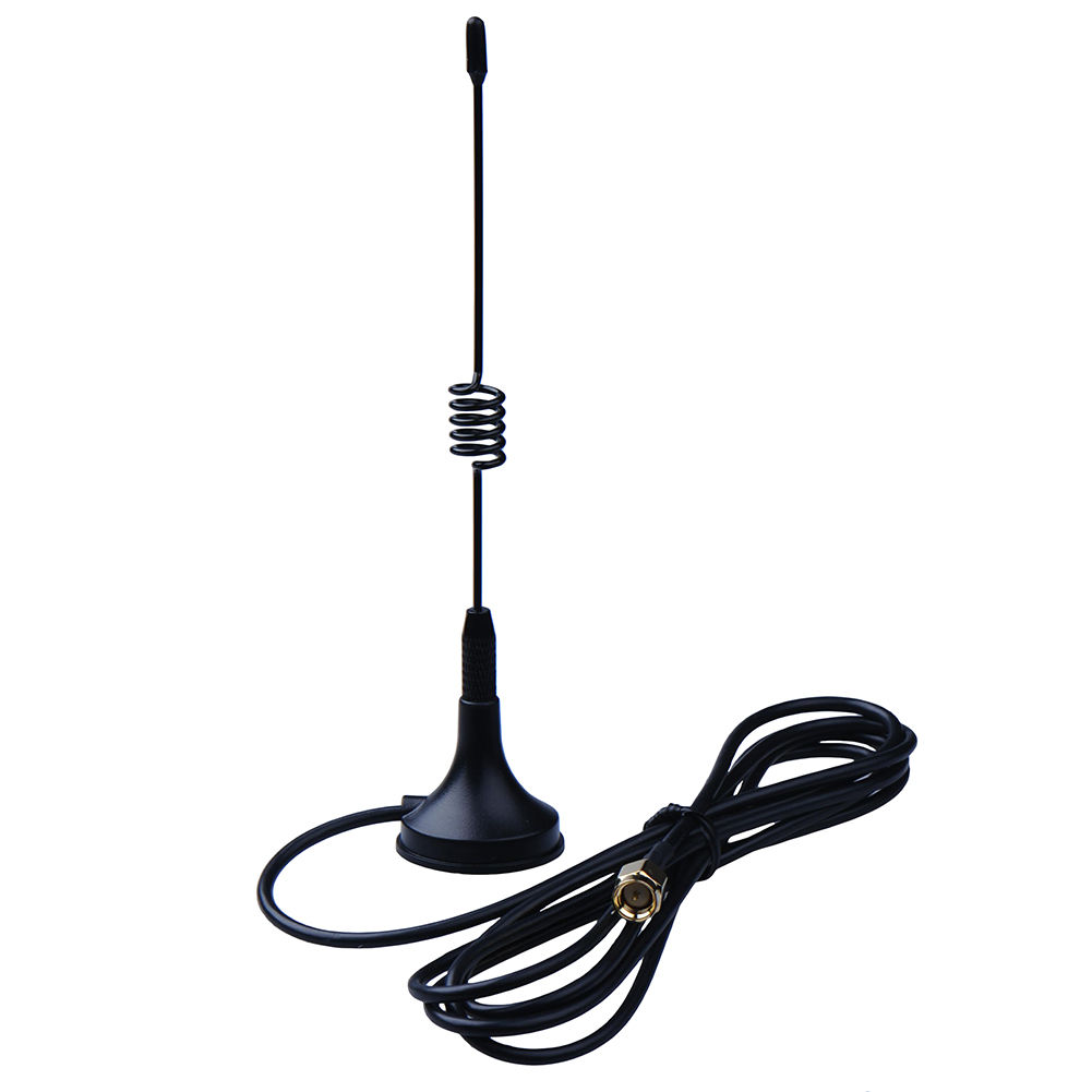
I would suggest to purchase a ready made patch antenna or a Ground Plain whip, connected via 20-30cm of quality 50ohm coax (usually a part of the antenna).
There are dozens of GSM antennas (with coax and connector, 1-8dBi gain) available for a few $.
I would suggest to purchase a ready made patch antenna, connected via 20-30cm of quality 50ohm coax (usually a part of the antenna).
There are dozens of GSM antennas (with coax and connector, 1-5dBi gain) available for a few $.
The secret sauce if you want to build a SWR meter for higher frequencies is a microwave detector diode. Something like this…
http://www.ebay.co.uk/itm/Avago-Agilent … dl6lUYmpnw
… and of course the ability to solder very small things, but I think if you managed to assemble the “GSM GPRS Module at 1.93$!!!!!” you are already over qualified. ![]()
If you do decide to build rather than buy an antenna, then you can make it highly directional, and as large as you please (visits from the local regulatory authorities notwithstanding of course ![]() ), which may be the only practical way you can get a usable signal in a remote location.
), which may be the only practical way you can get a usable signal in a remote location.
Do bear in mind, I am not encouraging you to flout the appropriate regulations in your country, so obviously you proceed at your own risk.
If you don’t want to build, as Pito pointed out, there is always ebay to fall back on.
However I cannot vouch for the claims of any of these devices, so try them and see if they live up to their spec. Look for low VSWR (<1.5) and high gain (5dB or better), and the correct frequency bands (900/1800MHz, *NOT* 433MHz) not that you will be able to verify these claims without a SWR meter of course ![]()
Perhaps something like this… http://www.ebay.co.uk/itm/Magnetic-Base … Sw~OVWy1oL .. would be a good starting point.
http://www.ebay.co.uk/itm/2G-3G-3DBI-PC … Swv-NWYTX-
and a lot of others, with max 10-30cm long coax.
Why? 0.1inch plays a significant role when you tune an UHF antenna (you may go fully off, see ie. http://colinkarpfinger.com/blog/2010/th … na-design/ even the guy tunes 2.4GHz one), so it seems to me a pcb etched antenna is more precise than a whip antenna with loading coil.. 1-3dBi is enough (still much better than a bended paper clip).
3m long RG174 coax or, RG58 one – try to avoid it for any price
I will cut the 3m coax if the attenuation will be too high, and try to place the module close to the window, although this move will seriously decrease the WAF …
+CSQ:99,99
Would it make sense to place the delivered small antenna close to the window and use a 3m coax cable to connect it to the module?
+CSQ:99,99
Would it make sense to place the delivered small antenna close to the window and use a 3m coax cable to connect it to the module?
GSM bands.JPG
PS: what about using a ceramic multilayer GSM antenna from a scrap mobile phone (wired via 10-20cm long coax)?
This would work, and has the advantage of being a tried and tested design, however it will obviously be no better in terms of performance than the original mobile phone. Some of the larger designs, or indeed a simple full wave or half wave dipole centred roughly on the 900 MHz centre frequency may in fact perform significantly better. In other words two very long paper clips may actually be as good as the ceramic multilayer device, and two 13″ straight wires arranged as dipole may be better still. If you need to use a directional antenna in order to cover larger distances, you might have to try a yagi or some other variant, which would give you the ability to point more of the available RF energy at your distant cell tower. This however leads to greater complexity, and potentially may fall foul with the authorities if you are not careful.
