- Selection_002.jpg (9.11 KiB) Viewed 506 times
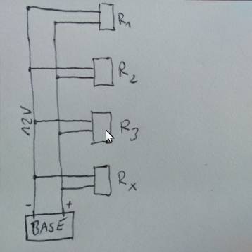
Shall the MapleM be the initiator (the Base) shorting the 12V??
Or, the MapleM shall be the R3 – receiving the signal via pulse on 12V??
When shorting the 12V you need 2 switches most probably:
1. to switch the +12V rail off the power source (ie. a high-side pmosfet), and after some small delay
2. to short the +12V against GND (ie. nmosfet) to generate the precise 12us pulse, and after some small delay then
3. to switch +12V back on.
EDIT: Maybe It would be easier if I would say that this is an intercom simillar to this one:
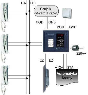
- IioHAS_3000_Magistrala.JPG (20.56 KiB) Viewed 463 times
In other word, do you need to crowbar the 12V with a few milliohms of short, or would a short of a few ohms, or tens of ohms be more appropriate?
The reason I ask, is that a dead short will provide a huge spike of energy, as the current will be high, but a few ohms, or tens of ohms will limit the current and therefore the switch required can be less robust. Does the system in question specify what a “short” is?
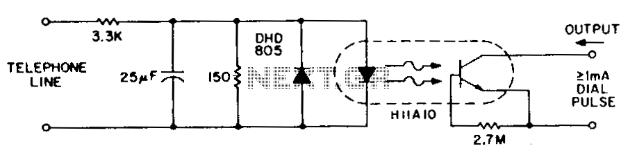
BTW most pulse dialling doesn’t rely on shorting, but rather on loop disconnect of a current loop. https://en.wikipedia.org/wiki/Pulse_dialing
It is possible in these systems to dial by “flashing the hook” at the correct rate to simulate the rotary dialler, this requires a little practice, but once learned, you can achieve pretty consistent results simply by clicking the hook switch at the correct rate.
EIT: You might also like to take a look at this.. -> https://www.sparkfun.com/tutorials/51
… and this …
.. and this …
[ahull – Thu Aug 10, 2017 12:54 pm] –
BTW most pulse dialling doesn’t rely on shorting, but rather on loop disconnect of a current loop. https://en.wikipedia.org/wiki/Pulse_dialing
It is possible in these systems to dial by “flashing the hook” at the correct rate to simulate the rotary dialler, this requires a little practice, but once learned, you can achieve pretty consistent results simply by clicking the hook switch at the correct rate.
Maybe this is how it works. But I’m unable to click the hook with 16us 21 times ![]()
![]() What circuit do I need for that ?
What circuit do I need for that ?
To be honest I took saleae logic analyzer and connected to those 2 wires by a voltage divider and I recorded all pulses. I don’t know how it works but I’d like to do the same in reverse. To be able to dial from receiver.
[konczakp – Thu Aug 10, 2017 1:11 pm] –[ahull – Thu Aug 10, 2017 12:54 pm] –
BTW most pulse dialling doesn’t rely on shorting, but rather on loop disconnect of a current loop. https://en.wikipedia.org/wiki/Pulse_dialing
It is possible in these systems to dial by “flashing the hook” at the correct rate to simulate the rotary dialler, this requires a little practice, but once learned, you can achieve pretty consistent results simply by clicking the hook switch at the correct rate.Maybe this is how it works. But I’m unable to click the hook with 16us 21 times

To be honest I took saleae logic analyzer and connected to those 2 wires by a voltage divider and I recorded all pulses. I don’t know how it works but I’d like to do the same in reverse. To be able to dial from receiver.
Do you have some example images of the signalling from your logic analyser?
Are you sure the line voltage of the system runs at 12V DC? Often phone (PBX) systems run at a notional +50V DC (more commonly +48V DC), and rely on current sensing rather than voltage sensing as this is far more reliable over long cable lengths. https://pbxbook.com/other/trunks.html
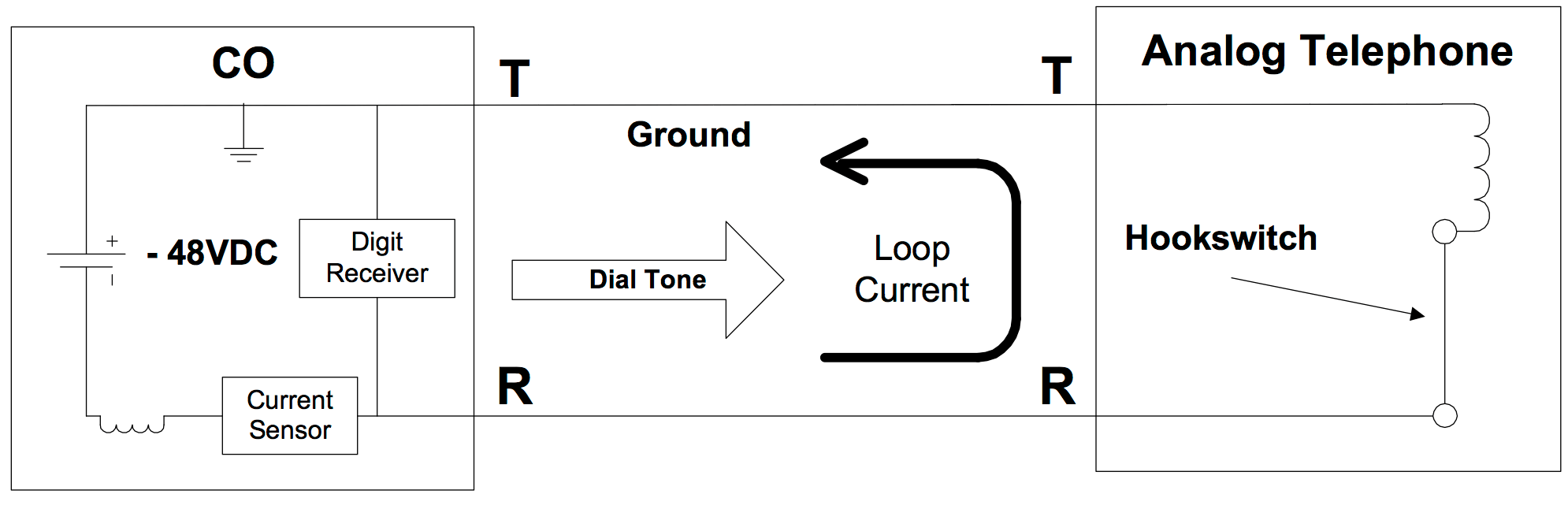
There is of course nothing to suggest that your system works this way, other than the fact that this is a very common standard.
Do you have the manufacturer, model number and spec and/or schematics of the intercom?
What is the current drawn by the R1..Rx phone?
Does the Base switch to zero Volt? It could be the Base switches from 12V to 6V (for example) – still enough voltage to power the phones and the phone can easily read the pulses..
(Translation => https://translate.google.co.uk/translat … rev=search )
I also don’t have any device fast enough to measure voltage in time of 16us when it is going to low. I’ve attached to my earlier post file with captured pulses from logic analyzer but this capture was made with voltage divider so I don’t know if it is going really low to 0v. But I could imagine that the uc is connected via capacitor to the 12V and when the line goes low then the uc is powered for a very short time from capacitor. But maybe this is a bad approach. I don’t have knowledge about it. I also know that when the base is sending receiver number (address) at the beginning then this communication is digital and after that everything goes in analog way. It is like:
power line is at 12-14V
1. long low for reset
2. receiver number
3. wait time
4. start to ring (few rings with delays between each ring) and wait for off-hook to start the conversation.
5. off-hook – power line is going to about 5V and analog communication is started
6. on-hook when end of talk – power line goes to 12V
I haven’t measure the current drawn by the receiver because the current is meaningful only when You want to pick-up the phone and start the conversation. I know that there are no SSR switches going so fast (I wrote it in my first post). How can I distinguish how it really works and what to do to to be a second base in the same circuit?
Maybe its time to take the cover off one of the slaves, and take some pictures, so we can identify the chipset and circuitry involved in communications.
Can you borrow an oscilloscope? By my back of the envelope calculation, a 16uS period suggests a relatively low bandwidth signal of the order of 62,500 Hz (62.5kHz), so you should be able to see that on the “pig-o-scope” or any of the low cost scopes from ebay/ali express.
[konczakp – Fri Aug 11, 2017 10:16 am] –
Ok so I’ve made a few calls and I will borrow today 200HHz scope. Write me then please what to measure an when ?
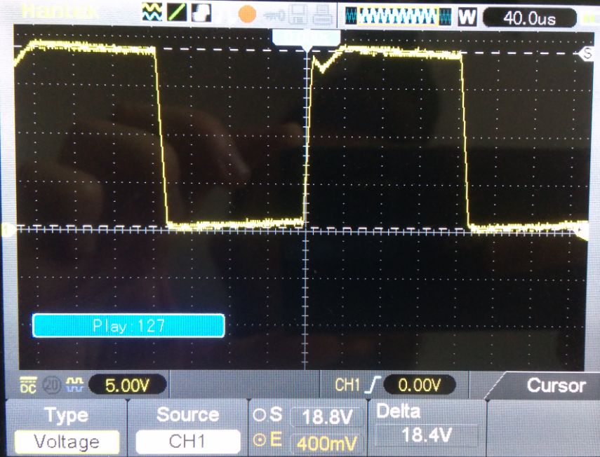
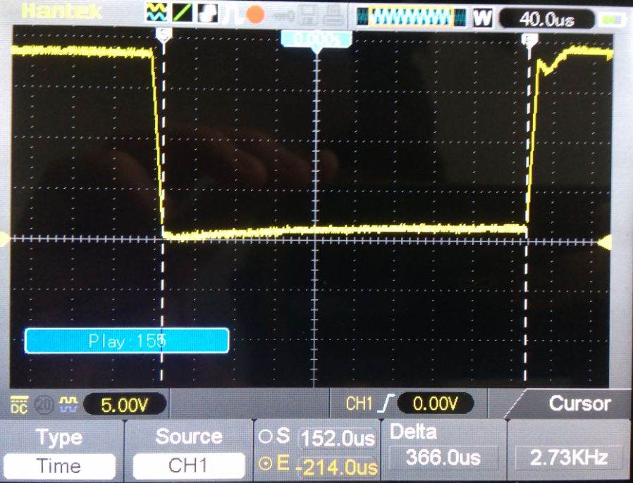
You will need to take a few pictures of the waveforms, so we can see what is what.
units on the line all have local regulators.
Why not just put a low level signal on the line and either tap it off with
a capacitor or even transformer.
You could use a simple tone or even a phase modulation that rides on
top of the DC level.
Most regulators can handle 100Hz with good isolation.
Most power supplies that put out amps, do not take kindly to shorts.
Dwight
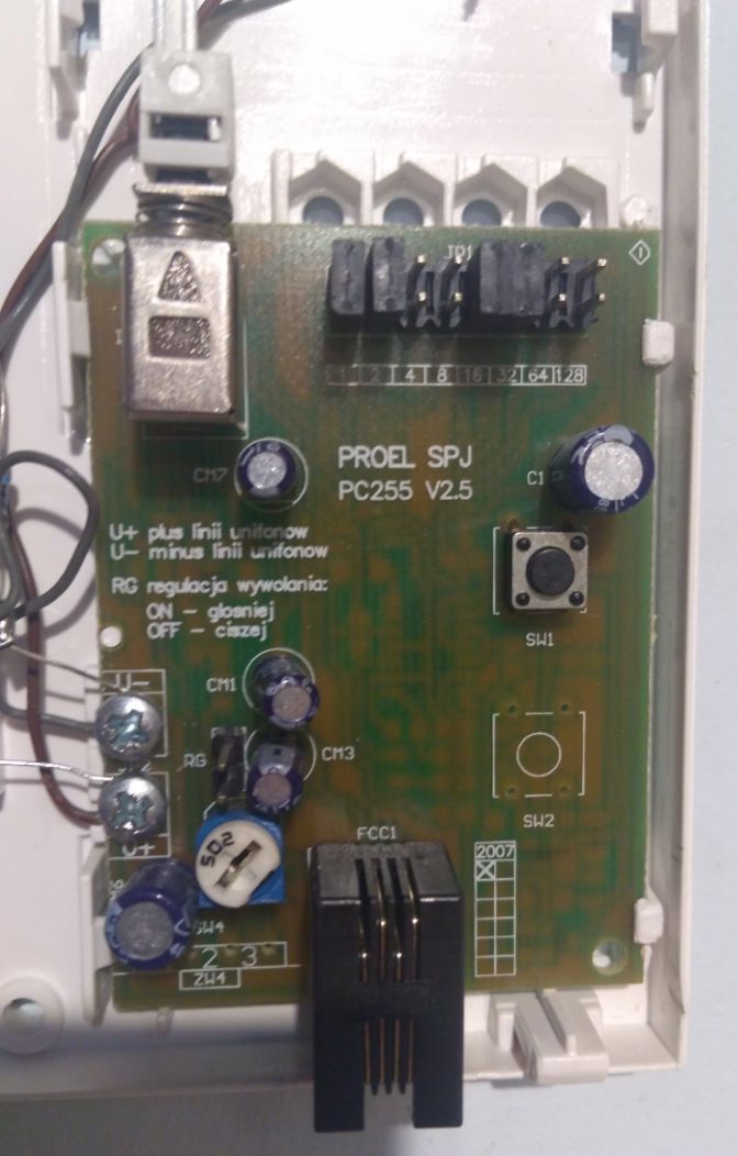
Side one:
- IMG_20170812_182241.jpg (79.09 KiB) Viewed 315 times
- IMG_20170812_172537.jpg (90.21 KiB) Viewed 315 times
- IMG_20170812_172750.jpg (95.09 KiB) Viewed 315 times
- IMG_20170812_173405.jpg (88.53 KiB) Viewed 315 times
There is none micro-controller in the phone. So the phone numbers are somehow hardwired on the pcb for the specific phone R1–Rx. Yes, there are the pin headers on the top you may set with an actual phone number.
The chips there are: 40103 – 8bit binary counter with presets inputs, which counts the pulses and compares with the number preset with the jumpers, and 4093 – 4x nand gates doing some timing (few RCs at its pins).
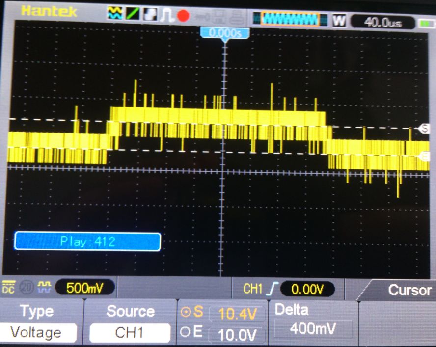
So it pulses 10V->10.4V->10V on your picture..
[Pito – Sat Aug 12, 2017 5:56 pm] –
Your recorded dialing pulses – it seems to me your measurement is 400mV pulse 308us long on top of 10V.
So it pulses 10V->10.4V->10V on your picture..
Then it would be very strange because logic analyzer would not show pulse for a 400mv change, I think. And Why the ringing signal would be made in a different manner than Receiver number signal ( 0v as Low signal )? This chip 40103 would recognize 400mV change ? But still, how can I pull the rail to low even if this would be only for ring signal ?
To be able to communicate with other receivers. I think i need to do short circuit for a very short time (12us) to generate Low state on the power line.
That’s a very odd way to communicate to anything. Before you proceed any further, I would strongly suggest that you confirm that’s indeed the case.
With that said, using a mosfet, properly rated for this application, would be the simpkiest solution.
You may also check into relays, etc. As an alternative.