But I bought some $1, RF based, motion detectors from eBay and they arrived the other day
Anyway, several people have blogged about them already, but no one seems to know how they work.
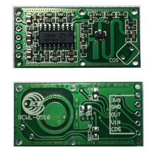
There is a github repo with reference information https://github.com/jdesbonnet/RCWL-0516 , but the IC on the board now seems to be a RCWL 9196, which appears to be very similar, if not identical to a BISS0001 http://www.ladyada.net/media/sensors/BISS0001.pdf
These module have a connection for Vin, 3.3V, GND, OUT, and CDS.
They run fine from 3.3V (the Vin seems to be if you want to supply from 5V etc), and OUT signal goes high for several seconds if the module detects movement.
BTW. The CDS is some sort of control to disable the device during the daytime e.g. using a LDR (light detector)
Anyway, thats all well and good, but not much use for speed detection, so I poked around the main IC with my scope and found an interesting analog signal on pin 12, which the the output of the 2nd stage OpAmp.
So I soldered a wire from that pin, to PA0 on a BluePill and wrote some simplistic code to do Serial.print(analogRead(PA));delay(10);
And moving my arm I can see the response straight away
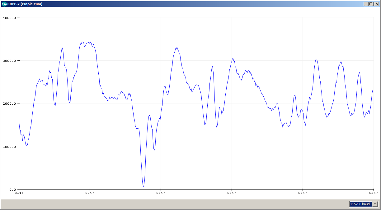
- motion_waveform1.png (38.67 KiB) Viewed 3125 times
And… unfortunately this device does not look like its suited to measuring the speed of distant objects.
In the middle of this graph is the data you get as a car drives past (within 1m of the sensor)
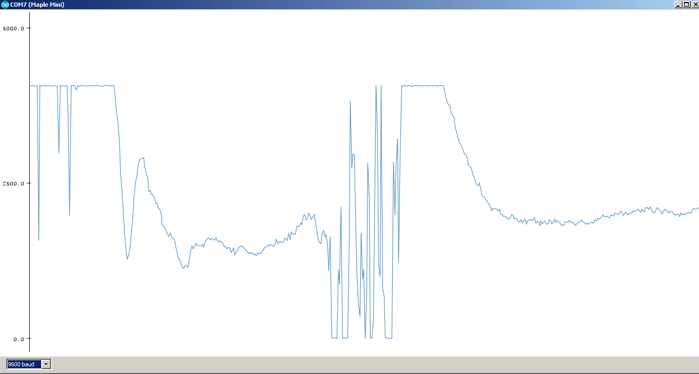
- passing_car.png (71.74 KiB) Viewed 3107 times
The other way to do this would be to use two modules at a set distance apart, say 100cm with a directional wave guide to bounce the signal in a narrow beam off passing objects, and measure the time between the two beams being broken. Two tin cans would possibly work, or two small parabolic reflectors. I’ll need to see if they have any 8cm cans in the supermarket, though I suspect if I get my digital callipers out and start measuring the baked beans, they may report me to the authorities. ![]()
EDIT: Roughly what time frame are we looking at in these two graphs? Do you have the raw data? How many samples per second did you take?
EDIT2: CDS = Cadmium sulphide, used in light dependent resistors. -> https://en.wikipedia.org/wiki/Photoresistor so, yes there is a facility to change the device to be only active in the dark (or by swapping the pull up resistor and the CDS photo-resistor only active in the light).
EDIT3: You might find this interesting as it is sort of related.. -> http://pcfarina.eng.unipr.it/Differenti … ration.htm
Last point is: when the hell one has the need to differentiate or integrate an audio signal? In reality, this often occurs when “strange” types of transducers have been used: for example, an accelerometer, so the sampled signal is an acceleration, and the user wants to transform it into velocity (simple integration) or displacement (double integration). And, of course, the opposite is also possible: if one has sampled the position of a vibrating surface (for example by means of a laser distance meter), and wants to obtain velocity or acceleration, then he has to differentiate the recorded signal once or twice…
I just had the same idea, so I soldered a wire to the input from the RF section (pin 14) but there is too little signal there to be usable and I I see on the BluePill is noise.
I did look at that signal on the scope, but as far as I could tell, it seems have virtually the same sort of waveform that output on pin 12, just a lot weaker.
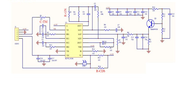
Looking at the schematic for the board
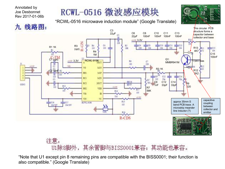
I can see that the opamp which has inputs on pins 15 and 14 and out on 16, has RC network into the inverting input, and the inverting input also has a series RC network to GND.
I am not an analog electronics expert, so I can’t really make a comment on what that whole part of the circuit is doing.
But my guess is that its probably a differentiator. I could try removing C4 and see what happens, but getting the SMD components back onto the board would a challenge.
Actually I already removed C18 which is in the feedback path of the 2nd OpAmp, but it didnt seem to make any difference to the what I’m detecting on the Blue Pill.
I have 3 of these, so I could sacrifice one of them, and keep the other 2 in factor configuration.
I’d not noticed the example application design.
You’re right.. I think its identical, which makes me wonder whether any design went into that part of the circuit.
Its almost as if someone found an effect, where they got a voltage output from an RF oscillator which changed when things were moved in close proximity to it.
And they just strapped on a normal PIR detector IC, mainly because of its triggering and hold time etc.
i don’t think the waveform I get on the output if the second opamp, makes any sense if the input from the RF section is a voltage that represents the speed of the moving object.
It looks far more like reflections going in an out of phase. i.e the faster the object moves towards or away from the sensor, the higher the frequency of the observed sinewave.
Effective range is also a bit odd. I find that no matter how fast I move an object, or how big the object is. It does not get detected at all beyond approx 5m.
Btw that is the same design as the Proximity Fuse used by US forces in second half of WWII mainly in Pacific theater – a 220MHz single tube oscillator, working as mixer too, 2-3 tubes as an amplifier and filter, 1 tube the fuse switch – all put into a fuse used with 120mm shells, fired off with 5000G acceleration. The shell rotated 3000rev/minute, when close to the airplane the reflecting waves mixed with the oscillator, because of rotation of the projectile and antenna diagram shape it created a low frequency tone maybe 100Hz, that tone was amplified, filtered, and when its amplitude was good enough the final tube ignited the fuse..
The WWII device does sound like it operated in the same way.
I dont think these devices detect inductance, as I tried waving lenths of wire ( usb cables ) about 2m from the detector, but there was no noticable change to the output.
I dont know about capacitance, but I would have thought the dielectric constant of air would not yield much change in capacitance , just my moving my hand a few metres from the device.
I think its more likely that its reflections which cause the observed effect, but its really hard to test this, e.g. measure if the peaks and troughs in the output, correspond to the wavelength of the device; Because indoors there will be refletions from reflections, so it wont have a simple / single radial emission pattern.
I also spotted a more comprehensive description here -> https://www.elecrow.com/rcwl-0516-micro … 100ma.html
Specifications
Operating Voltage: 4-28V
Operating Current: 2.8mA (typical); 3mA (max) <<< Interesting, I wonder how much RF power they produce.
Detection Distance: 5-9m
Transmitting Power: 20mW (typical); 30mW (max)
Output Voltage: 3.2-3.4V
Output Voltage Driving Capacity: 100mA
Trigger Way: repeat trigger
Output Control Low Level: 0V
Output Control High Level: 3.3V
Operating Temperature: -20~80 celsius
Storage Temperature: -40~100 celsius
The radiative element appears to be about 1cm dia., so perhaps I need to be looking for a smaller tin can for my wave guide experiments.
Sounds like the same boards I have.
Hookup is easy. Just connect to the Gnf, and 3.3 for power.
Then solder a wire onto pin 12 of the IC, to ready the analogue signal.
BTW.
I have been going the analogue IC circuit some thought, and I think I know roughly what it does.
The input voltage from the RF osc comes into the first opamp’s non inverting input, via a low pass filter combined with a divider network.
The first opamp, amplifies the signal from the osc and more crucially, the RC network in the inverting input is used so that the steady state output from them first opamp, ends up at vcc/2
I have noticed that the voltage on the output of the second opamp, stays at maximum for several seconds after I power up the board, and I think this is the charge time of the RC network in the inverting inout of the first opamp.
The problem with this system, is that the device is only ever going to be able to detect changes.
E.g. If for example an object placed at 1m from the device caused the OSC voltage to remain at 0.001v higher than when it was not placed there.
We would get an initial change at the output of OpAmp1, but the RC network in its inverting output, would soon charge up, to negate the change in the input from the OSC.
I think that if the inverting input on OpAmp1 was set to a calibrated voltage, equal to the initial steady state output from the OSC, we would get more interesting results.
I think we would see a voltage from the OSC that represented the interference to the OSC caused by reflected RF from the objects in its environment, and moving an object by the wavelength of the OSC / 2 would cause the maximum change to steady state output voltage.
However, the only way I can think of to build this, would be to remove the capacitor from the RC network on OpAmp1’s inverting input, and drive the input with a calibration voltage from a pot or possibly from the MCU.
I will measure the voltage on the inverting input, and see if its practical to put a pot into the circuit, but I suspect as the OpAmp is quite high gain ( probably thousands), setting the voltage in this way may be difficult
We would get an initial change at the output of OpAmp1, but the RC network in its inverting output, would soon charge up, to negate the change in the input from the OSC. I wonder if the time taken for the RC network to bring the system back to equilibrium has any significance.
A quick calculation of (3.3v/2) / 5 secs = about 0.3 volts per second.
If I put a scope on the output of the OSC the signal changes caused by movement seem to be quite small, e.g. in the order of perhaps 30mV
So they would be compensated for in about 1/10 a sec.
I will have to double check those values, but I do see the signal returning to steady state, pretty quickly.
Perhaps not that in 1/10, but perhaps worst case, 0.5 sec
I will fire up my test rig again ( once I resolder a wire which snapped of at the BP.)
BTW. Any ideas how to set the steady state calibration
BTW. Any ideas how to set the steady state calibration
I tried to measure the voltage from the OSC and its around 400mV, but the fluctuation seems to be only a few mV and I’m unable to look at it when I switch to DC input on the scope, so I don’t know if it holds at steady state or not.
The offset correction / calibration voltage may be hard to set if it needs to be within a new mV ![]()
http://robohub.org/lidar-vs-radar-a-det … omparison/
This sensors are very sophisticated. They have mulit-beam, multi core and build in environmental models and teams of about 50 algorithmn and software developers work on that projects.
But probably they can give a hint on how to measure some useful data with the cheap 1$ sensors:
Make an FFT and watch the results when moving some objects. Probably you might see some frequency peaks correlated with your movements.
I think these $1 devices would need a lot of hardware modifications to make them usable for anything other than a motion detector
I’ve also ordered a $5 Doppler radar module, which albeit only measures speed, but could be useful
I looked on AliExpress an eBay to see if there were any other radar module, but they all appeared to be basically the same.
But I did some across a “Time of flight” Infrared laser distance sensor
http://www.ebay.com.au/itm/GY-VL53L0XV2 … SwImRYMoyI
Which is an interesting product, and made by ST
http://www.st.com/en/imaging-and-photon … 53l0x.html
It looks like a very short range LIDAR, with range of around 1 to 2 m indoors, (less outdoors)
It will substitute the ultrasonic sensor in the small robotic car kit.
Measures absolute range up to 2mhttp://www.rogerclark.net/investigating … r-modules/
Taking the signal from pin 12 seems the best option to me as it allows for the MCU application code to choose the trigger threshold, or perhaps a more complex triggering algorithm etc
I don’t think it will be much use for anything other than short range motion sensing. But that has plenty of uses.
here is an article about an Arduino speed radar:
http://www.hjberndt.de/soft/radar/
It is in German but probably google can translate ..
12Euro.. + shipping(??)
EDIT: 4-6Euro within EU and DHL..
Rapa Nui seems not to be on the list…
http://shop.weidmann-elektronik.de/inde … ID=&coID=1
Probably you can find another distributor on ebay:
http://www.ebay.co.uk/itm/Radarsensor-1 … Sw1~JZPyb9
No problem, I fly often to DE, I was born in a Lufthansa flight
I saw that as well. I have 2 of those modules, but have not had time to even power them up.
I see that the output voltage is very low, but appears to be AC, so I was thinking of using one of those $1 audio amplifier modules, to boost the output, before feeding into a blue pill.
I just need to remember where I put the audio amplifiers ![]()
[ahull – Thu Aug 10, 2017 11:09 am] –
I’ve not had much spare time recently, so I haven’t pursued this topic, but some of you might find this interesting.
wow, this means even formula1 cars on the racetrack won’t escape the speedtrap
![]()
http://www.stm32duino.com/viewtopic.php?f=19&t=2496
As this thread is mainly about the other (completely different) motion detector, where as the HB100 is a more conventional doppler radar module

