I’m a software engineer and only very lightly dabble in electronics. I’m running into some unknown territory with some 1 wire protocols on a couple of the controllers and I’m hoping I can ask some questions here for some help. If not are there any other general beginner electronics boards I can join?
The issue is with Nintendo controllers; the N64 and Gamecubes.
They both use a single 3.3v data line.
The 3.3v line is pulled high in the console so I need to mimic this in the STM32.
Do I need to pull the line high in the circuit with an external resistor? Is that the only way?
When I want to transmit on the line do I set the pin to OUTPUT_OPEN_DRAIN?
When I want to receive on the line do I need to set the pin to INPUT_PULLUP or FLOATING because of the external pullup?
I was able to send the poll command and read back the button states. Timing isn’t perfect. I need to account for some cycles lost to logic control and pin polling. I would dig to the metal and bypass the convenience methods but I haven’t yet discovered how much is being lost. [Update] The timing jitter was caused by usb interrupts during communication. I was able to communicate with the controller successfully by temporarily disabling interrupts during communication. I’m now moving onto some of the other controllers I have on hand, which currently is the SNES and GameCube controllers.
Many thanks!
I’m using a maple mini with 7 logic pins per controller to manage 4 controllers with one usb/maple mini. I know the teensy can load itself as 4 separate joysticks, I haven’t looked into it with the maple mini but I have seen someone working on the joystick HID on this forum. We’ll tackle that problem when we get to multiple controllers : )
I’m going to use some DB-15 connectors to console controller adapters so that I can plug in a large number of controller types into this system. The maple mini adapter can use multiple types of controllers at the same time, for example we can place a SNES controller on port1 and Sega Genesis controller on port2.
I’ve been collecting and writing the communication protocols for a couple of controllers. So far I’ve written bit-bangers for the SNES, N64, GameCube, Sega Genesis(Master System) and Sega Saturn controllers.
I’m using a cooperative task scheduler and those controllers are tasks that control their own polling timer. The highest priority task is one which looks for controller connections / disconnections. I’m going to use 4 of the pins on the DB-15 to create a nibble by hard-wiring a controller type identifier by soldering pins to the logic 3.3v pin.
Controller identification isn’t solidly planned out because of pin requirements, I think I’ll use a PISO Shift Register to capture the identification nibbles from the cable adapters. One issue with this method is that some adapters can work for multiple controllers (for example Sega controllers and most that use the DB-9 connector).
When this task finds a new controller it puts that controllers task on the task list on keeps track of which tasks/controllers are connected to which ports. When it finds a controller is removed it also removes the task from the scheduler.
I’ll see if I can move what I have into a public github repo tonight.
Thanks!
The issue is with Nintendo controllers; the N64 and Gamecubes.
They both use a single 3.3v data line.
The 3.3v line is pulled high in the console so I need to mimic this in the STM32.
Do I need to pull the line high in the circuit with an external resistor? Is that the only way?
When I want to transmit on the line do I set the pin to OUTPUT_OPEN_DRAIN?
When I want to receive on the line do I need to set the pin to INPUT_PULLUP or FLOATING because of the external pullup?
Many thanks![/quote]
Looking at the attachment, it appears that the proper resistor pulled to +Vcc is appropriate.
As far as the input/output CMOS pin, are you planning on doing raw port control? Generally, one (like myself) would think that a library would be used, as in this example: http://themikerogers.com/2010/09/20/sup … er-part-3/ but you can certainly do all of the manipulations inline.
Disclosure: I have never interfaced a game controller, so while my input may be meager, I do find the project interesting ![]()
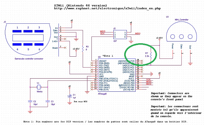
- x2wii_n64.jpg (137.94 KiB) Viewed 2018 times
I updated the main post.
I was able to communicate with my N64 controller last night. It was late and I only had an hour of free time but it’s a great first step. I won’t have time tonight but if I can get the timing issue fixed on Thursday if there’s enough time left I’ll put it up on github otherwise it will need to wait for the weekend.
Right now my 4us bits are running about 4.5us long, and when reading back the button states at some point the timing must slip because I stop seeing commands being sent from the STM32. I think I fall into an infinite loop while waiting for a state that was probably missed (or waiting for a last bit that probably already passed).
I started mapping out pins and realized there aren’t enough 5v tolerant pins to handle 4 controllers at the same time. To solve the issue I am looking at using an 8-bit logic level converter to provide an extra two bi-directional 5v pins per controller.
The BOM is now 1 x maple mini, 4 x 3.3k pull-up resistors, 1 x 8-bit logic level converter, and 2 x 8bit PiSo shift register.
I also need to start looking into how I can get the maple mini to be recognized as 4 joysticks.
Good Day!
I think it’s posible the maple mini can be detected as 4 joyticks at the same time. The current HID report descriptor should be modified to include 4 sections of joysticks each with its own id, and the HIDJoystic class methods should also be modified to acept an id argument, although I have not tried it yet.
I think the Teensy 3.x is 5v tolerant only in the digital pins but not on the analog ones so I don’t know if they’re enough, but as Roger says, you’d better check.
libarra
My electronics engineer father-in-law had a saying: if you need one, buy four. if you need four, buy twenty. The Teensy is too rich for that statement.
But I do have 4 maple minis on hand and 5 logic level converters on order ![]()
I’ll have time this weekend to play with the joystick HIDs to get the four in.
I got the SNES controllers working, I can’t tell if my GameCube controller is dead (it’s a 3rd party I bought from a thrift store) but it’s not responding.
Thanks!
Price of the Teensy is a problem for me as well, especially as shipping outside the US adds a lot to the cost, I think it add 50% to the price.
Which is why I never bought one.
I guess if the STM32 board, like the Maple mini, did not exist, I would have to buy a Teensy.
But now that they do exist, I bought 5 and its still cheaper than one Teensy.
Im sure the Teensy is a better board, but not cost effect for what I want either
I refactored the tasks so that there aren’t tasks for each type of controller but instead a joypad port task that manages one usb joystick and the corresponding input port. There will be 4 of these tasks in the scheduler and what were individual controller tasks are now classes with a static Run method that handles communication and returns the button state.
Dynamically creating, tracking, and removing tasks is not recommended without a memory controller. All the new and delete would have crufted up the memory space.
Sometimes I like to play in emulators even when I have the console and the game, and having the original controller for that purpose comes very usefull.
I’m currently working on a similar project, with the dreamcast crontroller in a wireless mod using stm32 and NRF24L01+ or Esp8266 (these arrieved a week ago but haven’t tested yet). The Maple Bus used in the dreamcast controller ports is a bit tricky, but fun to experiment with. It uses 2 wires for bidirectional communication (half duplex) and the purpose of each wire is changing between data and clock on every bit transfer. With that, 2 bits are transfered in only 1 cycle ![]()
Thanks for the tip and link on using Rick’s delay_cycle using DWT register to get better timing control, i’m going to take a good look at that. Timing it’s definitely one of the biggets problems when emulating/reading the controller protocol.
I’m also interested in the descriptor to have 4 controllers reported in just 1 stm32 by usb (but i’m not sure if it can actually handle protocol emulation for 4 controllers at the same time). Please tell us if you manage to get it working.
I have now worked out how to program the firmware on this BLE device using the Arduino IDE and using another stm32f103c board flashed with firmware to act as the programmer.
Checkout my youtube stuff… its the latest video
It may be a more flexible option than the 24L01
But ESP8266 is also an excellent device, it just kinda depends if you want to use Wifi or some other form of comms. But the nRF51822 is Bluetooth, so it can also interface to devices like tablets and phones ( which have BLE capability)
I built out a dev board that wires up two ‘ports’ using screw posts. I couldn’t find dip-switches so I ended up putting 8 tri-state sliding switches on the edge. I haven’t yet begun making the stm report as multiple joysticks but I’ve been reading into USB programming. I may also include a custom device IN device and some software on the computer to report what type of controller is connected, that may even advance all the way to custom button mapping.
I’ve looked into the dreamcast controller protocol, it is wild. I picked up some used controllers on ebay and some VMUs to play with but haven’t begun on them. Running multiple dreamcast controllers might be too taxing :\
I’ve also thought about using timers and dma to handle communication with some of the controllers but haven’t done more than read the manual and go cross eyed.
And I’ve started looking into building a custom pcb to run the connections. The protoboard took 3 weeks of free time to wire and the ‘real’ board would have twice as many connections.
Im not sure exactly how you setup the USB data structures to do this, but you could look at what liboopencm3 does.
In fact you may end up having to code using libopencm3 rather than the Arduino API to accumplish this, because at the moment no one has had time to look into how to make the Arduino code have a composite device.
I think @jcw was investigating, replacing the libusb low level code with the usb code from libooencm3, but it is a long way down his To Do list ![]()
I moved and had another kid, things that take up more time then imaginable. After packing up my lab it stayed packed up, even to this day. But I have begun unpacking it. I never did stop thinking about this project.
How far I got: I was able to get the PoC to report a single device and multiple controllers. I think I did this by reporting a single device with multiple collections in the HID Report. I had to heavily modify the board code and stm32 code, I got the n64 and snes working as gamepads in windows but I did this by hardcoding the controller and not detecting which one was connected. At this point I had to pack everything up.
I have come up with some redesigns since then:
Drop the two 3v3-5v line level adapter. It will be too slow to communicate with the dreamcast controllers.
Drop the two PISO shifters. These were used for controller type detection. I have a new method now.
Drop the 5v transistor switch. This was used for sega controllers.
I was originally trying to get 4 game controllers out of one microcontroller, this required the above hardware to work. Instead, I’m going to use one microcontroller to read inputs from 2 game controllers. Then have one act as slave and report the joystick mapping to the master who will act as the usb device to the computer.
With one uc to two game pads I will have all the 5v tolerant gpio I need, I can use 4 adc pins to read voltages from the controller adapters to detect controller type. In an interesting turn, I am going to use the N64 1-wire communication protocol to communicate between the two uc.
So I’m going to start reworking the PoC layout and software, look into getting the latest smt32duino code and finding a cleaner way to implement the usb joysticks.
-drew

