I’d like to do BPSK with a Blue Pill board for an ultrasound project.
I managed to generate a 40KHz PWM signal and I’d like to modulate the phase of each pulse (10-30 pulses max). Do you think it’s possible with a STM32F1? I saw this project https://github.com/ChrisMicro/BluePillSound/ where it’s generating several king of signal but it’s working at lower frequencies.
Thanks a lot,
Jean-Paul
probably it is not necessary to use PWM.
You may simply use digital levels as output.
The Phase shift could be done discrete. The timer resolution at 72MHz raleted to 40kHz US-frequency should be accurate enough.
Cheers,
ChrisMicro
I need to do other things while the PWM is generated so I cannot have a blocking digitalWrite.
Thanks,
Jean-Paul
There are hardware timer examples in Rogers repo and a HAL-hardware timer with interrupt in the STM32Generic repo.
Ok thanks, it’s seems working. I setup timer1 to trigger this ISR:
void handler_ISR(void) {

static uint8_t count = 0;
digitalWrite(PA8, raw_pulse[count]);
digitalWrite(PB13, !raw_pulse[count]);
count++;
if (count >= 70){
count = 0;
timer.pause();
}
}
But it does not change the phase, it just allows any freq up to 280khz for pwm.
If I have time during the weekend, I will add the API for this
It would be really good, if you could ad an audio PWM. This means an interrupt after each sample to update the value.
I have done almost something like this here. Except that it is a “bit” interrupt instead of PWM which doubles the interrupt load and does not provide rail to rail PWM ( a distance must be kept to time=0 or time=period ).
For Audio 280kHz would be too much because it causes a high interrupt load. Something arround 48kHz would be sufficient.
Audio PWM would be interesting.
I see you have a library which does PWM audio, so I’m not sure if its appropriate for me to just to incorporate the code into the core.
I guess it depends how big it is, and whether it makes things like the blink sketch bigger, as the community is generally against code bloat of the core.
You mean this one?
It is not meant to be a library. It is more a collection of code examples where I tried arduously step by step to get somehow sound out of the BluePill.
Before this, I did it for various MCU architectures with the mentioned PWM interrupt but it was every time a hard way to get it running.
This time I didn’t want to do it again and I tried to circumvent the deep microcontroller related stuff and tried to use what was available ( At the end it turned out I should have started with STM-cube which would probably not had cost me more time ).
If there would have been an example in your STM32 repo showing how to output a sine wave or a wav-file it would have saved me many hours of experimenting.
So far it would be really helpful if you could incorporate simple audio examples ( sine wave, modulated sine wave in interrupt, wav-file output ) in your repo.
Taking some of the more interesting example out of my repo would require some serious clean up, I think because they still have some not so elegant remains of the development process inside.
I used the fastWrite fonction that you wrote. The BPSK is working but I have a problem, I need 2 outputs with a 180° phase shift so I did in the interrupt:
  fastWrite(PIN_A, raw_pulse[count]);

fastWrite(PIN_B, !raw_pulse[count]);
Use pins of a single port – read the port, modify the 2 bits, write it back.
Or, use special port manipulation instructions:
http://www.stm32duino.com/viewtopic.php?t=1220
Pitos way is the fastest one but the big time delays come because you are reading the pins before writing. If you would prepare the bits in two variables before writing it would be much faster.
BTW.: Why do you want to transmit data by ultrasound? What is the application?
The delay between the phases will be 0ns if using single port and writing bits with 1 instruction.
An example:
..

// prepare the pin values, output pins are PB1 (in phase) and PB0 (phase + 180deg)

uint32_t data = ((raw_pulse[count] & 0x1) << 1 ) + (!(raw_pulse[count] & 0x1));
uint32_t result = GPIOB->regs->IDR; // read the entire PB port
result = (result & 0xFFFFFFFC) | data; // modify PB1 and PB0 with your values only
GPIOB->regs->ODR = result; // single instruction write back to the port PB
..
Thanks, I tried Pito’s code and it’s working. For the time delay I don’t think it’s a problem because it will be in every interrupt so the whole data is sent with a delay but the wave form is kept correct.
I’m doing a phase-coded ultrasonic distance measurement. I’d like to increase accuracy and range of a HC-SR04 sensor using Barker codes.
Thank,
Jean-Paul
It may FM modulate your signal a little bit (the bits duration will vary).
Disabling other interrupts (systick, usb..) may help as well..
that means 0.34mm at 1us time accuracy. I think the interrupt is much more accurate than 1us ( if not blocked ) and I wouldn’t expect a influence.
I’m doing a phase-coded ultrasonic distance measurement. I’d like to increase accuracy and range of a HC-SR04 sensor using Barker codes.
Interesting .. whats currently the accuracy of a HC-SR04 ?
Barker code page 27, hw incl. arduino
Is there a pdf available somewhere??
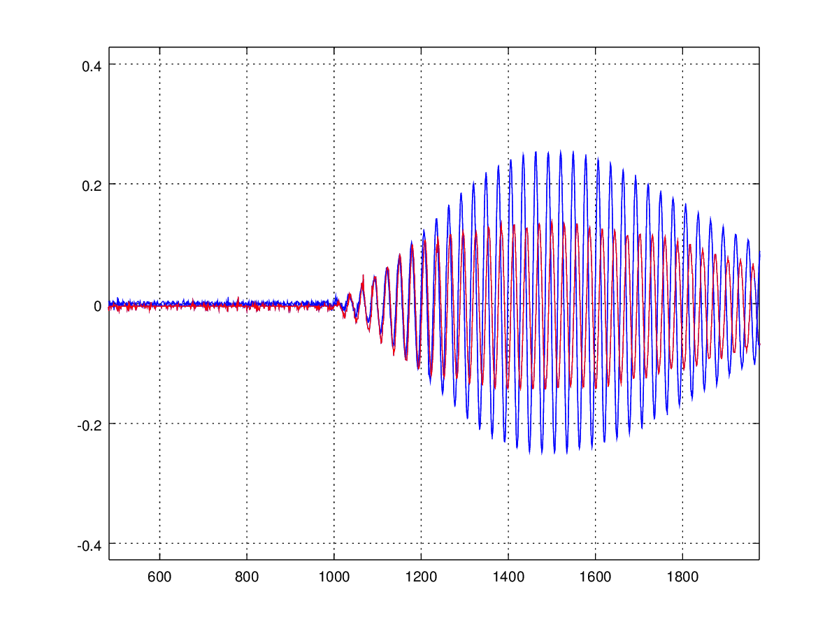
blue: 24 pulses signal
red: phase shift of 180° after 12 pulses
Did you send the Barker code?
B13= 1111100110101
To be honest I don’t know if acuracy will be better, but range should be because of pulse compression.
I don’t understand you plot? What is red? Received signal ?
Jean-Paul
red and blue are both received signals. See the code:
/*

US modulatéd sender

hardware:

STM32F103 BluePill, 72Mhz

Arduino Framework:

STM32GENERIC
Aug. 2017 ChrisMicro
*/
#include "HardwareTimer.h"
#define SOUNDPIN PB1
#define SIGNALLENGTH 24
uint8_t Signal[SIGNALLENGTH];
int SignalIndex = 0;
void interrupt()
{
if (SignalIndex < SIGNALLENGTH)
{
digitalWrite(SOUNDPIN,Signal[SignalIndex]);
SignalIndex++;
}
}
void setup()
{
pinMode(LED_BUILTIN, OUTPUT);
pinMode(SOUNDPIN, OUTPUT);
// T=1/f = 1/40000
int frequency_Hz = 40000;
//Timer1.setPeriod(1000000/frequency_Hz/2); // half period interrupt
Timer1.setPeriod(6); // 41.67khZ half period interrupt ( error of factor 2 in setPeriod )
Timer1.attachInterrupt(interrupt);
Timer1.resume();
}
void loop()
{
digitalWrite(LED_BUILTIN, !digitalRead(LED_BUILTIN));
// blue signal
for (int n = 0; n < SIGNALLENGTH; n++)
{
Signal[n] = n & 0x01; // zero degree phase signal
}
SignalIndex = 0; // send new Signal
delay(10);
// red signal
for (int n = 0; n < SIGNALLENGTH; n++)
{
if (n < SIGNALLENGTH / 2) Signal[n] = n & 0x01; // zero degree phase signal
else Signal[n]=(n-1) & 0x01; // 180 degree phase signal
}
SignalIndex = 0; // send new Signal
delay(10);
}
This is what I got:
Sent pulse

Sent and receiced at around 1.7m, with 20ms data.

I think the US has problem doing 180° phase shift. I think it’s better to do frequency shift but these sensors are low bandwith.
Jean-Paul
If you goal is to realize indoor positioning the new way is using UWB time of flight measurement. There are now the first application boards also usable with Arduino:
https://www.decawave.com/products/overview
Another option is the laser based Time Of Flight devices from STM.
There is another thread about using these,
I have some of the long range version, but the range is limited to below 2m
FFT of pulses at 41 KHz

FFT of pulses at 44 KHz

I need to find a better transducer…
Could this be the right one?
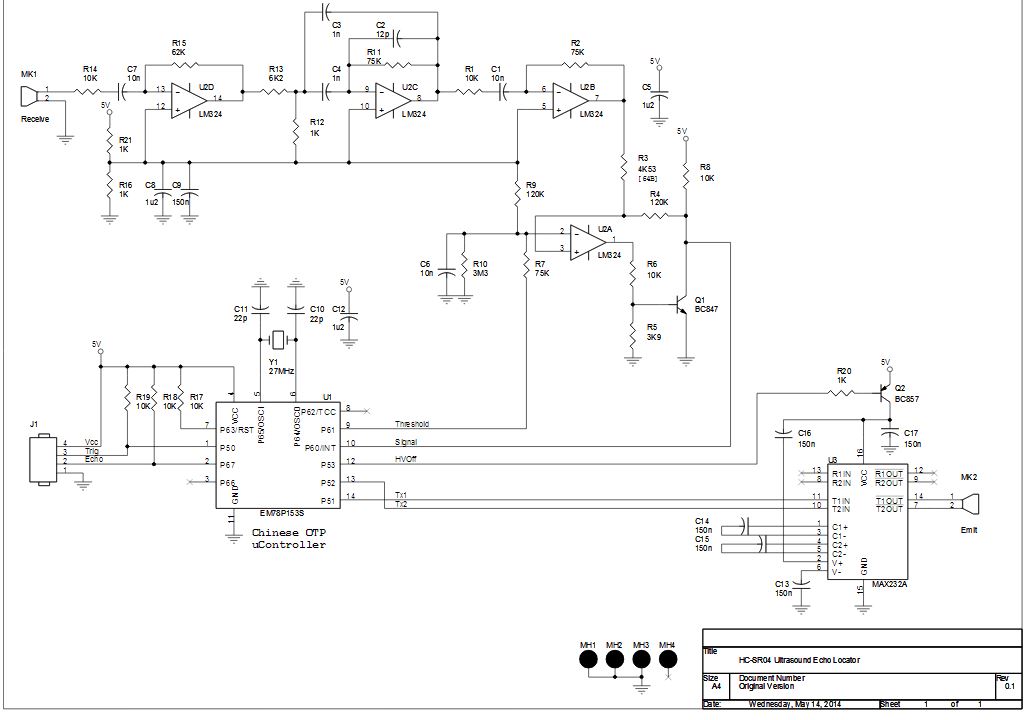
Yes I think it’s right. But on mine I don’t have the 2 transistors!
srp
I think Q1 is only for threshold level adaption which is probably not really necessary and Q2 is for power saving which they removed to save costs.
The interesting point is the MAX232 RS232 driver which they misuse as sender driver.

