This one is better than the one I recently purchased, and posted about here, in the sense that it appears to breaks out the VBat (so no nasty surprises or surgery needed) and has an RTC resonator. The price is about the same.
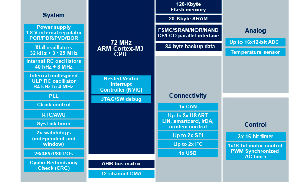
This is a medium density (RB) device i.e.
3 × USARTs
3 × 16-bit timers
2 × SPIs, 2 × I2Cs, USB,
CAN, 1 × PWM timer
2 × ADC
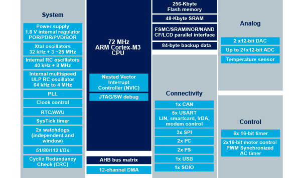
Was the RCT, so 256KB of Flash and 48KB of RAM, DACs, and a couple other things.
That is still available for about $10.
32Khz crystals are pretty cheap, so it can be added if needed.
Was the RCT, so 256KB of Flash and 48KB of RAM, DACs, and a couple other things.
That is still available for about $10.
32Khz crystals are pretty cheap, so it can be added if needed.
Was the RCT, so 256KB of Flash and 48KB of RAM, DACs, and a couple other things.
That is still available for about $10.
32Khz crystals are pretty cheap, so it can be added if needed.
Was the RCT, so 256KB of Flash and 48KB of RAM, DACs, and a couple other things.
That is still available for about $10.
32Khz crystals are pretty cheap, so it can be added if needed.
Oh i had not paid attention to that, so vBAT is hardwired to 3.3V? no 0 resistor or any other easy means to disconnect it?
Oh i had not paid attention to that, so vBAT is hardwired to 3.3V? no 0 resistor or any other easy means to disconnect it?
~Straw
~Straw
Oh i had not paid attention to that, so vBAT is hardwired to 3.3V? no 0 resistor or any other easy means to disconnect it?
~Straw
do you use 2 pins as can High and Can low ?
do you use an arduino Can library to get it to work ?
does the vbat problem mean one of the pins is hardwired to +3.3v
are any of the pins 5v tolerant ?
sorry for all the questions !!
do you use 2 pins as can High and Can low ?
do you use an arduino Can library to get it to work ?
does the vbat problem mean one of the pins is hardwired to +3.3v
are any of the pins 5v tolerant ?
sorry for all the questions !!
do you use 2 pins as can High and Can low ?
do you use an arduino Can library to get it to work ?
does the vbat problem mean one of the pins is hardwired to +3.3v
are any of the pins 5v tolerant ?
sorry for all the questions !!
I will try harder next time ![]()
BTW, I am aware we don’t have a board definition (variant) for the RB
The Maple rev3 is a RB board, so I will need to take that one, then rearrange the pin map into a sensible order
Personally I don’t know if the RB boards are particularly good value, Its only got the same Flash and RAM as the F103CB, but I suppose its got more GPIO
Thanks.
Actually I also had that idea after I posted the message
I just don’t need any remapping for the Generic F103RB, but I can use the PIN MAP etc from the Nucleo merged into the Maple rev 3
(well I thought you did some remapping, but I’d need to double check)
I find it is really handy to have a version of STM32CubeMX installed just to play around with the on-board peripherals and their configurations. This has given me heaps of insight as to what does what and what I can and can’t (or better say should and shouldn’t) do. I would refer to this regularly and take what it says to be higher in authority being from the manufacturer. What it can’t do is compensate for when a library has been written/modified to use the wrong pin, etc.
The good thing is that in most cases it will work anyway, even when it shouldn’t but what I noticed with all of it that is relevant to this conversation is that a pin will only really be PWM if it has a timer/channel function attached to it. They also usually only have one hardware interrupt line attached to each port as well…
<…>
What it can’t do is compensate for when a library has been written/modified to use the wrong pin, etc.
<…>
<…>
What it can’t do is compensate for when a library has been written/modified to use the wrong pin, etc.
<…>
<…>
Oops Ray, that wasn’t a dig at you guys. Sorry for my thoughtless comments.
<…>
I thought “Hey, they’re both ARM Cortex processors, right? They should share many registers, calls and functions, right? How hard can it be? Right?…”
Cheers.
<…>
Oops Ray, that wasn’t a dig at you guys. Sorry for my thoughtless comments.
<…>
I thought “Hey, they’re both ARM Cortex processors, right? They should share many registers, calls and functions, right? How hard can it be? Right?…”
Cheers.
Talking about IR, I have been porting STM SIRC library. I stopped a couple of weeks ago to do other things with the timers, but should be back at it soon.
What IR protocol were you trying to use?
Talking about IR, I have been porting STM SIRC library. I stopped a couple of weeks ago to do other things with the timers, but should be back at it soon.
What IR protocol were you trying to use?
http://www.ebay.com/itm/Clear-stm32f103 … 3cfd3d0266
This one does break out the VBAT pin but lacks the 32kHz crystal (and possibly optional caps, depending on the chosen crystal). It has the 20 pin Jtag header and also breaks out what looks like all of the other pins. I don’t need one… but I ordered one anyway. ![]()
Currently the cheapest Blue Pill looks to be $4.33 US (£2.78 GBP) shipped.
<…>
I don’t need one… but I ordered one anyway.
<…>
<…>
I don’t need one… but I ordered one anyway.
<…>
Guess they used something like bing translator to translate it from chinese to russian, then to spanish and finally to english ![]()
~Straw
http://www.ebay.com/itm/Clear-stm32f103 … 3cfd3d0266
This one does break out the VBAT pin but lacks the 32kHz crystal (and possibly optional caps, depending on the chosen crystal). It has the 20 pin Jtag header and also breaks out what looks like all of the other pins. I don’t need one… but I ordered one anyway. ![]()
Currently the cheapest Blue Pill looks to be $4.33 US (£2.78 GBP) shipped.

It shows up in qstlink as “ST Link V2 / Nucleo found!” so I set “STM Nucleo F103RB (Stlink)” as the board type in the Arduino IDE and fired a blink sketch on to it.
LED is on PB0 – and it is blinking away nicely. Looking at the chip, it says STM32F103R8T6 – ST-Link reports..
2015-07-29T18:29:32 INFO src/stlink-common.c: Device connected is: F1 Medium-density device, id 0x20036410

2015-07-29T18:29:32 INFO src/stlink-common.c: SRAM size: 0x5000 bytes (20 KiB), Flash: 0x10000 bytes (64 KiB) in pages of 1024 bytes

2015-07-29T18:29:32 INFO src/stlink-common.c: Attempting to write 11972 (0x2ec4) bytes to stm32 address: 134217728 (0x8000000)

There are some interesting options with this board, the onboard LED (PB0) can be un-jumpered (with J9), as can the two USB port lines D+ (PA12) and D- (PA11) (with J11 and J10 respectively). not sure how useful that will be, but that along with the logical ordering of the pins on the headers, shows some thought has gone in to the design. I’m warming to this particular impulse buy. ![]()
Thanks for your first impressions.
It sounds like its one of the better boards to buy.
STM32F103RBXX
STM32F103RCXX
I have a iTeadMaple which is a F103RB, so I could try it later, however I suspect that really, the RB is a CB in a larger package, and that the RC is made with a different die.
In include/series/stm32.h there is code which takes the device model number MCU_STM32F103RC and sets some defines e.g.
#elif defined(MCU_STM32F103RB)

#   define STM32_F1_LINE                STM32_F1_LINE_PERFORMANCE

#   define STM32_NR_GPIO_PORTS          4

#   define STM32_SRAM_END               ((void*)0x20005000)

#   define STM32_MEDIUM_DENSITY
#elif defined(MCU_STM32F103RC)
# define STM32_F1_LINE STM32_F1_LINE_PERFORMANCE
# define STM32_NR_GPIO_PORTS 4
# define STM32_SRAM_END ((void*)0x2000C000)
# define STM32_HIGH_DENSITY
I have a iTeadMaple which is a F103RB, so I could try it later, however I suspect that really, the RB is a CB in a larger package, and that the RC is made with a different die.
I fired a sketch on to the STM32F103R8T6 board compiled for the STM32F103CBT6 – and the board now behaves rather oddly.
If I fire a sketch on to it which is compiled for the STM32F103RBT6 (the “STM Nucleo F103RB (ST Link)” board type in the IDE) it works, except, the USB port no longer enumerates.
However if I fire a sketch on to the board for a STM32F103C8T6 (the “Generic STM32F103C Series” board type in the IDE) the sketch works and the USB port enumerates. This is slightly mind boggling, so I wondered what the rest of you make of it.
Currently I am running the 6502 emulator on the board and it works perfectly… except the code is compiled for the STM32F103C8T6 ![]()
The Nucleo is unlike a lot if the other boards. Its Serial is via its Stlink chip, which has a separate virtual serial driver.
Re:LED not flashing on the RC
I have a nagging feeling there is a mistake in the PIN MAP on the RC. I vaguely recall having issues ages ago, where some GPIO pins wold not work, but this could have been the SPI SS issue (long before we knew what it was)
Try a different GPIO pin. In fact try a few more, in case there is a big mistake in the PIN MAP
The Nucleo is unlike a lot if the other boards. Its Serial is via its Stlink chip, which has a separate virtual serial driver.
The Nucleo has special Serial mapping defined in its variant folder.
You would be better off modifying the Maple board definition, as I think this is closer to a generic board than the Nucleo (which has a number of special configs)
LIST
10 PRINT TAB(28);"AMAZING PROGRAM"
20 PRINT TAB(15);"CREATIVE COMPUTING MORRISTOWN, NEW JERSEY"
30 PRINT:PRINT:PRINT:PRINT
100 INPUT "WHAT ARE YOUR WIDTH AND LENGTH";H,V
102 IF H<>1 AND V<>1 THEN 110
104 PRINT "MEANINGLESS DIMENSIONS. TRY AGAIN.":GOTO 100
110 DIM W(H,V),V(H,V)
120 PRINT
130 PRINT
140 PRINT
150 PRINT
160 Q=0:Z=0:X=INT(RND(1)*H+1)
165 FOR I=1 TO H
170 IF I=X THEN 173
171 PRINT ".--";:GOTO 180
173 PRINT ". ";
180 NEXT I
190 PRINT "."
195 C=1:W(X,1)=C:C=C+1
200 R=X:S=1:GOTO 260
210 IF R<>H THEN 240
215 IF S<>V THEN 230
220 R=1:S=1:GOTO 250
230 R=1:S=S+1:GOTO 250
240 R=R+1
250 IF W(R,S)=0 THEN 210
260 IF R-1=0 THEN 530
265 IF W(R-1,S)<>0 THEN 530
270 IF S-1=0 THEN 390
280 IF W(R,S-1)<>0 THEN 390
290 IF R=H THEN 330
300 IF W(R+1,S)<>0 THEN 330
310 X=INT(RND(1)*3+1)
320 ON X GOTO 790,820,860
330 IF S<>V THEN 340
334 IF Z=1 THEN 370
338 Q=1:GOTO 350
340 IF W(R,S+1)<>0 THEN 370
350 X=INT(RND(1)*3+1)
360 ON X GOTO 790,820,910
370 X=INT(RND(1)*2+1)
380 ON X GOTO 790,820
390 IF R=H THEN 470
400 IF W(R+1,S)<>0 THEN 470
405 IF S<>V THEN 420
410 IF Z=1 THEN 450
415 Q=1:GOTO 430
420 IF W(R,S+1)<>0 THEN 450
430 X=INT(RND(1)*3+1)
440 ON X GOTO 790,860,910
450 X=INT(RND(1)*2+1)
460 ON X GOTO 790,860
470 IF S<>V THEN 490
480 IF Z=1 THEN 520
485 Q=1:GOTO 500
490 IF W(R,S+1)<>0 THEN 520
500 X=INT(RND(1)*2+1)
510 ON X GOTO 790,910
520 GOTO 790
530 IF S-1=0 THEN 670
540 IF W(R,S-1)<>0 THEN 670
545 IF R=H THEN 610
547 IF W(R+1,S)<>0 THEN 610
550 IF S<>V THEN 560
552 IF Z=1 THEN 590
554 Q=1:GOTO 570
560 IF W(R,S+1)<>0 THEN 590
570 X=INT(RND(1)*3+1)
580 ON X GOTO 820,860,910
590 X=INT(RND(1)*2+1)
600 ON X GOTO 820,860
610 IF S<>V THEN 630
620 IF Z=1 THEN 660
625 Q=1:GOTO 640
630 IF W(R,S+1)<>0 THEN 660
640 X=INT(RND(1)*2+1)
650 ON X GOTO 820,910
660 GOTO 820
670 IF R=H THEN 740
680 IF W(R+1,S)<>0 THEN 740
685 IF S<>V THEN 700
690 IF Z=1 THEN 730
695 Q=1:GOTO 830
700 IF W(R,S+1)<>0 THEN 730
710 X=INT(RND(1)*2+1)
720 ON X GOTO 860,910
730 GOTO 860
740 IF S<>V THEN 760
750 IF Z=1 THEN 780
755 Q=1:GOTO 770
760 IF W(R,S+1)<>0 THEN 780
770 GOTO 910
780 GOTO 1000
790 W(R-1,S)=C
800 C=C+1:V(R-1,S)=2:R=R-1
810 IF C=H*V+1 THEN 1010
815 Q=0:GOTO 260
820 W(R,S-1)=C
830 C=C+1
840 V(R,S-1)=1:S=S-1:IF C=H*V+1 THEN 1010
850 Q=0:GOTO 260
860 W(R+1,S)=C
870 C=C+1:IF V(R,S)=0 THEN 880
875 V(R,S)=3:GOTO 890
880 V(R,S)=2
890 R=R+1
900 IF C=H*V+1 THEN 1010
905 GOTO 530
910 IF Q=1 THEN 960
920 W(R,S+1)=C:C=C+1:IF V(R,S)=0 THEN 940
930 V(R,S)=3:GOTO 950
940 V(R,S)=1
950 S=S+1:IF C=H*V+1 THEN 1010
955 GOTO 260
960 Z=1
970 IF V(R,S)=0 THEN 980
975 V(R,S)=3:Q=0:GOTO 1000
980 V(R,S)=1:Q=0:R=1:S=1:GOTO 250
1000 GOTO 210
1010 FOR J=1 TO V
1011 PRINT "I";
1012 FOR I=1 TO H
1013 IF V(I,J)<2 THEN 1030
1020 PRINT " ";
1021 GOTO 1040
1030 PRINT " I";
1040 NEXT I
1041 PRINT
1043 FOR I=1 TO H
1045 IF V(I,J)=0 THEN 1060
1050 IF V(I,J)=2 THEN 1060
1051 PRINT ": ";
1052 GOTO 1070
1060 PRINT ":--";
1070 NEXT I
1071 PRINT "."
1072 NEXT J
1073 END
Ready
RUN
AMAZING PROGRAM
CREATIVE COMPUTING MORRISTOWN, NEW JERSEY
WHAT ARE YOUR WIDTH AND LENGTH? 10
?? 10
Out of memory Error in line 110
Ready
RUN
AMAZING PROGRAM
CREATIVE COMPUTING MORRISTOWN, NEW JERSEY
WHAT ARE YOUR WIDTH AND LENGTH? 5
?? 5
. .--.--.--.--.
I I
:--:--:--:--: .
I I
: :--:--:--:--.
I I
:--:--:--:--: .
I I I I
: : : :--:--.
I I I I I I
:--:--:--:--:--.
Ready
I have managed to scramble the STM32F103 brain on a couple of occasions by deliberately writing images for the wrong processor variant to the board.
Perhaps the most interesting brain f*ck I managed to accomplish so far, left the poor thing completely unresponsive, and I though I had consigned it to the great smoke cloud in the sky, however I did a little googling and discovered that even if you appear to have completely poached its brains, you can still program the board with the ST-Link if you hold down the reset button as you program. A useful trick I thought worth sharing.
So for example the following incantation will re-write the Bootloader2 to the board if you hold down the reset button and keep it pressed while the command runs.
st-flash --reset write generic_boot20_pb0.bin 0x08000000
Another trick if you don’t have a reset button is to plug connect the power to the board just after you press connect on the STLink GUI (windows), as it has a small timeout while looking for the board, which is enough if you get it right to allow STLink to access the board.
Like you said pressing reset has the same effect, or simply press and release reset just after telling STLink to connect to the board.
Actually, setting Boot0 to HIGH also lets STlink connect, as it seems to connect when the device is in its internal hardware serial bootloader.
Selecting the wrong board type from the menu can cause all sorts of strange results, and appear to “brick” the board, but its always recoverable using STLink or USB to Serial + Boot0=HIGH.
Zip contains the following, most of which is derived from the generic_stm32f103c8 with appropriate changes where I spotted differences.
The main differences are obviously the extra GPIO pin definitions, but since this is a first draft, you would be well advised to sanity check what I have done.
./STM32F1/variants/generic_stm32f103r8/board.cpp
./STM32F1/variants/generic_stm32f103r8/board/board.h
./STM32F1/variants/generic_stm32f103r8/ld/bootloader_20.ld
./STM32F1/variants/generic_stm32f103r8/ld/common.inc
./STM32F1/variants/generic_stm32f103r8/ld/extra_libs.inc
./STM32F1/variants/generic_stm32f103r8/ld/flash.ld
./STM32F1/variants/generic_stm32f103r8/ld/flash_c8.ld
./STM32F1/variants/generic_stm32f103r8/ld/jtag.ld
./STM32F1/variants/generic_stm32f103r8/ld/jtag_c8.ld
./STM32F1/variants/generic_stm32f103r8/ld/mem-flash.inc
./STM32F1/variants/generic_stm32f103r8/ld/mem-jtag.inc
./STM32F1/variants/generic_stm32f103r8/ld/mem-ram.inc
./STM32F1/variants/generic_stm32f103r8/ld/ram.ld
./STM32F1/variants/generic_stm32f103r8/ld/ram_c8.ld
./STM32F1/variants/generic_stm32f103r8/ld/vector_symbols.inc
./STM32F1/variants/generic_stm32f103r8/pins_arduino.h
./STM32F1/variants/generic_stm32f103r8/variant.h
./STM32F1/variants/generic_stm32f103r8/wirish/boards.cpp
./STM32F1/variants/generic_stm32f103r8/wirish/boards_setup.cpp
./STM32F1/variants/generic_stm32f103r8/wirish/start.S
./STM32F1/variants/generic_stm32f103r8/wirish/start_c.c
./STM32F1/variants/generic_stm32f103r8/wirish/syscalls.c
For suitable menu changes, apply the following diff to ../STM32F1/boards.txt
index 77ff7ba..a1c1b83 100644

--- a/STM32F1/boards.txt

+++ b/STM32F1/boards.txt

@@ -163,7 +163,6 @@ genericSTM32F103C.menu.device_variant.STM32F103CB.upload.maximum_size=131072

genericSTM32F103C.menu.device_variant.STM32F103CB.upload.ram.maximum_size=20480

genericSTM32F103C.menu.device_variant.STM32F103CB.upload.flash.maximum_size=131072
-
## STM32F103C8 -------------------------
genericSTM32F103C.menu.device_variant.STM32F103C8=STM32F103C8 (20k RAM. 64k Flash)
genericSTM32F103C.menu.device_variant.STM32F103C8.build.cpu_flags=-DMCU_STM32F103C8
@@ -187,22 +186,72 @@ genericSTM32F103C.menu.upload_method.serialMethod=Serial
genericSTM32F103C.menu.upload_method.serialMethod.upload.protocol=maple_serial
genericSTM32F103C.menu.upload_method.serialMethod.upload.tool=serial_upload
-
genericSTM32F103C.menu.upload_method.STLinkMethod=STLink
genericSTM32F103C.menu.upload_method.STLinkMethod.upload.protocol=STLink
genericSTM32F103C.menu.upload_method.STLinkMethod.upload.tool=stlink_upload
genericSTM32F103C.menu.upload_method.STLinkMethod.build.upload_flags=-DCONFIG_MAPLE_MINI_NO_DISABLE_DEBUG=1 -DSERIAL_USB -DGENERIC_BOOTLOADER
-
genericSTM32F103C.menu.upload_method.BMPMethod=BMP (Black Magic Probe)
genericSTM32F103C.menu.upload_method.BMPMethod.upload.protocol=gdb_bmp
genericSTM32F103C.menu.upload_method.BMPMethod.upload.tool=bmp_upload
genericSTM32F103C.menu.upload_method.BMPMethod.build.upload_flags=-DCONFIG_MAPLE_MINI_NO_DISABLE_DEBUG
+###################### Generic STM32F103R8/RB (Medium density 64 pin variants). See also Generic STM32F103R for higher density RC/RE devices ########################################
+
+genericSTM32F103R8.name=Generic STM32F103R(8/B) series
+genericSTM32F103R8.build.variant=generic_stm32f103r8
+genericSTM32F103R8.build.vect=VECT_TAB_ADDR=0x8000000
+genericSTM32F103R8.build.core=maple
+genericSTM32F103R8.build.board=GENERIC_STM32F103R8
+genericSTM32F103R8.upload.use_1200bps_touch=false
+genericSTM32F103R8.upload.file_type=bin
+genericSTM32F103R8.upload.auto_reset=true
+
+## STM32F103R8 -------------------------
+genericSTM32F103R8.menu.device_variant.STM32F103R8=STM32F103R8T6 (20k RAM. 64k Flash)
+genericSTM32F103R8.menu.device_variant.STM32F103R8.build.cpu_flags=-DMCU_STM32F103R8
+genericSTM32F103R8.menu.device_variant.STM32F103R8.build.ldscript=ld/jtag_c8.ld
+genericSTM32F103R8.menu.device_variant.STM32F103R8.upload.maximum_size=65536
+genericSTM32F103R8.menu.device_variant.STM32F103R8.upload.ram.maximum_size=20480
+genericSTM32F103R8.menu.device_variant.STM32F103R8.upload.flash.maximum_size=65536
+
+## STM32F103RBT6 -------------------------
+genericSTM32F103R8.menu.device_variant.STM32F103RB=STM32F103RBT6 (20k RAM. 128k Flash)
+genericSTM32F103R8.menu.device_variant.STM32F103RB.build.cpu_flags=-DMCU_STM32F103RB
+genericSTM32F103R8.menu.device_variant.STM32F103RB.build.ldscript=ld/jtag_c8.ld
+genericSTM32F103R8.menu.device_variant.STM32F103RB.upload.maximum_size=131072
+genericSTM32F103R8.menu.device_variant.STM32F103RB.upload.ram.maximum_size=20480
+genericSTM32F103R8.menu.device_variant.STM32F103RB.upload.flash.maximum_size=131072
+
+#---------------------------- UPLOAD METHODS ---------------------------
+
+genericSTM32F103R8.menu.upload_method.DFUUploadMethod=STM32duino bootloader
+genericSTM32F103R8.menu.upload_method.DFUUploadMethod.upload.protocol=maple_dfu
+genericSTM32F103R8.menu.upload_method.DFUUploadMethod.upload.tool=maple_upload
+genericSTM32F103R8.menu.upload_method.DFUUploadMethod.build.upload_flags=-DSERIAL_USB -DGENERIC_BOOTLOADER
+genericSTM32F103R8.menu.upload_method.DFUUploadMethod.build.vect=VECT_TAB_ADDR=0x8002000
+genericSTM32F103R8.menu.upload_method.DFUUploadMethod.build.ldscript=ld/bootloader_20.ld
+genericSTM32F103R8.menu.upload_method.DFUUploadMethod.upload.usbID=1EAF:0003
+genericSTM32F103R8.menu.upload_method.DFUUploadMethod.upload.altID=2
+
+genericSTM32F103R8.menu.upload_method.serialMethod=Serial
+genericSTM32F103R8.menu.upload_method.serialMethod.upload.protocol=maple_serial
+genericSTM32F103R8.menu.upload_method.serialMethod.upload.tool=serial_upload
+
+
+genericSTM32F103R8.menu.upload_method.STLinkMethod=STLink
+genericSTM32F103R8.menu.upload_method.STLinkMethod.upload.protocol=STLink
+genericSTM32F103R8.menu.upload_method.STLinkMethod.upload.tool=stlink_upload
+genericSTM32F103R8.menu.upload_method.STLinkMethod.build.upload_flags=-DCONFIG_MAPLE_MINI_NO_DISABLE_DEBUG=1 -DSERIAL_USB -DGENERIC_BOOTLOADER
+
+genericSTM32F103R8.menu.upload_method.BMPMethod=BMP (Black Magic Probe)
+genericSTM32F103R8.menu.upload_method.BMPMethod.upload.protocol=gdb_bmp
+genericSTM32F103R8.menu.upload_method.BMPMethod.upload.tool=bmp_upload
+genericSTM32F103R8.menu.upload_method.BMPMethod.build.upload_flags=-DCONFIG_MAPLE_MINI_NO_DISABLE_DEBUG
########################### Generic STM32F103R ###########################
-genericSTM32F103R.name=Generic STM32F103R series
+genericSTM32F103R.name=Generic STM32F103R(C/E) series
genericSTM32F103R.build.variant=generic_stm32f103r
genericSTM32F103R.build.vect=VECT_TAB_ADDR=0x8000000
genericSTM32F103R.build.core=maple
@@ -211,14 +260,6 @@ genericSTM32F103R.upload.use_1200bps_touch=false
genericSTM32F103R.upload.file_type=bin
genericSTM32F103R.upload.auto_reset=true
-
-#genericSTM32F103R.menu.device_variant.STM32F103RB=STM32F103RB
-#genericSTM32F103R.menu.device_variant.STM32F103RB.build.cpu_flags=-DMCU_STM32F103RB
-#genericSTM32F103R.menu.device_variant.STM32F103RB.upload.maximum_size=131072
-#genericSTM32F103R.menu.device_variant.STM32F103RB.upload.ram.maximum_size=20480
-#genericSTM32F103R.menu.device_variant.STM32F103RB.upload.flash.maximum_size=131072
-#genericSTM32F103R.menu.device_variant.STM32F103RB.build.ldscript=ld/stm32f103rb.ld
-
genericSTM32F103R.menu.device_variant.STM32F103RC=STM32F103RC
genericSTM32F103R.menu.device_variant.STM32F103RC.build.cpu_flags=-DMCU_STM32F103RC
genericSTM32F103R.menu.device_variant.STM32F103RC.upload.maximum_size=262144
no worries
I will merge your file(s) manually.
I’ve taken a look at your zip file, but we already have a generic_stm32f103r variant folder; which is used for the Maple rev3 and also the generic f103RC etc
I’m not sure if the existing folder has been extensively tested, but I’d have thought that to support the R8 we’d just need some different linker scripts and also another board.txt section ?
Or am I missing something ?
Thanks
Roger
Thats a good point.
I’ll need to break the convention a bit with the folder names.
I suppose it may have been better to have the variant folders based on device density / capabilities, and I suppose there is still time to change it.
But its probably easier for everyone if I have one called generic_stm32f103R8-RB i.e use the folder you created
I’ll take a look later
Thanks
Roger
Your patch to boards.txt gave errors for me, so…
I’ve gone for a hybrid solution..
I’ve added your new variant folder, with some minor changes to the linker scripts (generally just renaming).
I added your variant within the existing STM32F103R menu, as it looked strange to spit it into a separate menu.
I’ve also had to rename the stm32f103re_bootloader.ld in the existing generic_stm32f103r folder, just to be bootloader.ld, as both types of R series boards, need to have the same name for this file in their individual folders.
The linker script for the bootloader is a bit of a hack for all boards, because the Arduino menu system isn’t cascading, so the bootloader linker script is applied to all sub variants, hence needs to have the RAM and flash settings of the board with the most resources.
FYI. I did try to do a work around for the linker script issue (Several months ago), to see if I could pass variables e.g. from the Defines into the linker script, but after several hours of working my way through the various processes to get vars into the script from the compile command line, I found that linker variables are not supported by GCC in the MEMORY blocks in the scripts (arrrggghh moment).
Anyway, I won’t bore you with the details, but if you can download the repo again, and replace your variants folders and boards.txt and let me know if the new version works for you.
BTW. It compiles for me, but I don’t have a generic R8 or RB board to test it on.
Thanks
Roger
No worries.
Double check I got the MCU value correct… If I remember I will check it later
But I think it should generally be ok
Umm. I see what you mean.
I thought I had pushed those changes. I suspect the push failed and I didnt notice.
i.e if the server has something i need to pull first, because of a PR etc that is on the server and not on my machine.
I will take a look a little later after i get the machine in question fired up.
Edit.
Push failed the other day, but I think its worked now
Can you take another look.
/home/ahull/.arduino15/packages/arduino/tools/arm-none-eabi-gcc/4.8.3-2014q1/bin/../lib/gcc/arm-none-eabi/4.8.3/../../../../arm-none-eabi/bin/ld: cannot open linker script file /home/ahull/PersonalApps/Arduino.cc/beta/arduino-nightly/hardware/Arduino_STM32/STM32F1/variants/generic_stm32f103r8/{build.ldscript}: No such file or directory

collect2: error: ld returned 1 exit status

Error compiling.
Ok.
I will investigate
Can you download the latest boards.txt and try again.
I found a load of typos’ for STM32F103RB and STM32F103R8 which look very similar, i.e. and eight and the letter B look very similar unless you are paying close attention (I probably need much stronger glasses).
Anyway, fixing those mistakes seems to allow both the B and the 8 variant to compile
I fired on a simple RTC sketch that spits out the STM RTC time and also blinks the on-board LED every seconds and it works perfectly.
# Current time - 22:14:17 13/8/2015(BST)

# Current time - 22:14:18 13/8/2015(BST)

# Current time - 22:14:19 13/8/2015(BST)

# Current time - 22:14:20 13/8/2015(BST)

# Current time - 22:14:21 13/8/2015(BST)

# Current time - 22:14:22 13/8/2015(BST)

# Current time - 22:14:23 13/8/2015(BST)

# Current time - 22:14:24 13/8/2015(BST)

# Current time - 22:14:25 13/8/2015(BST)
