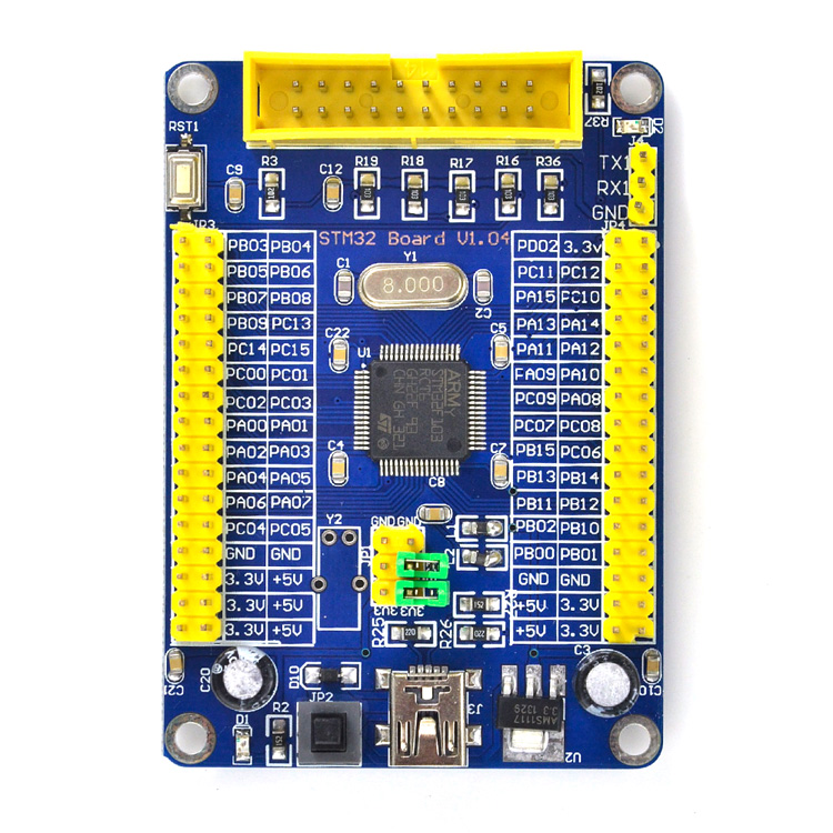
Just got this board from China:

At $9.39 the price is fair for a STM32F103RC, but this board looks like a unfinished prototype ![]()
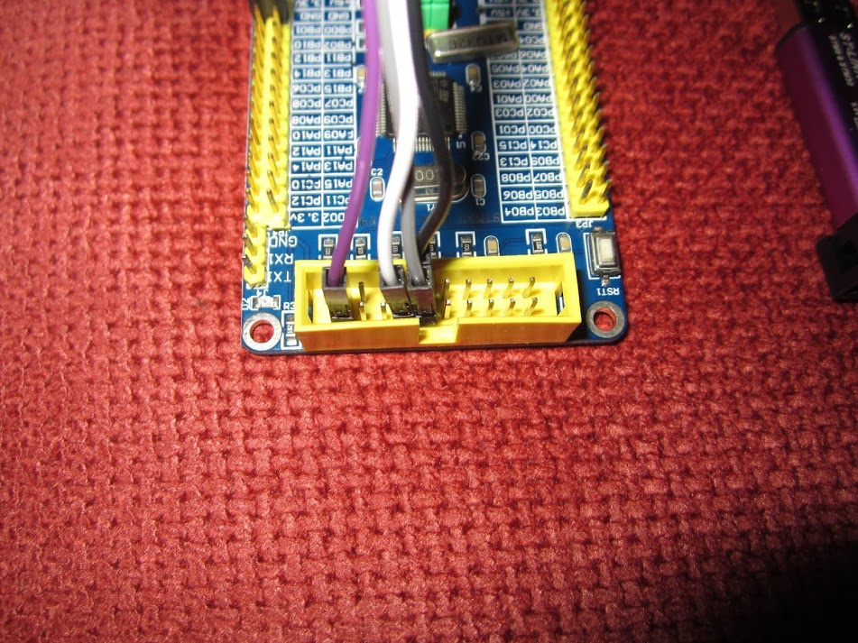
The ISP header has pins marked BT0 and BT1.
BT0 connects to Boot0 as expected but BT1 connects to nothing – I had to connect PB02 to GND and BT0 to 3V3 to program the board.
The pin marked NC connects to LED D2 so with the jumper in place the LED is on PD2.
The pins marked PF04, PF05, PF06 and PF07 is connected to GND, 3V3, GND and 3V3 ![]()
Pin PB9, PC13, PD0 and PD1 is missing on the headers. (PD0 and PD1 is OSC_IN and OSC_OUT so no problem with this)
BOOT1 is connected to the MCU boot1/pb02 pin thru a 10K resistor in mine.
By the way in all my tests it seems like I can write 512KB of unique data to the board.
If I try to start writing from a position over 40000, gives an error (I think st-link rejects it rather than the CPU), but I try to write starting at any position under that, even 3FFFF, and fill up to the 512KB limit, I can fill it up to that with no problem, and read back what I wrote, compare, etc.
EDIT: there is space for J1 in my board but nothing was soldered to it.
Well, J1 should be a jumper, and the function is to connect the 1k5 resistor from 3.3 to usb dp+. So to use USB in that board, you need to solder the jumper and put a jumper on it, or just solder a piece of wire closing the two points.
After that USB works flawless.
I still need to check what’s up with those PFxx ports you mentioned.
EDIT2: From looking at the pinout of the chip, looks like:
PF06 must be connected to VSS_2
PF07 must be connected to VDD_2
I see PB09 right next to PC13. They both are right next to PB07/PB08. I have not tested them though.
PF04 must be connected to VSS_4
PF05 must be connected to VDD_4
EDIT: I have modified the maple bootloader and works great in this board. At this point I don’t see any issue with the board to not recommend it, except that the pins PF04 to PF07 are mislabeled.
Item location: Shenzhen, China
Postage to: Worldwide
Excludes: APO/FPO, Alaska/Hawaii, US Protectorates, Africa, Central America and Caribbean, Albania, Andorra, Austria, Belarus, Bosnia and Herzegovina, Bulgaria, Croatia, Republic of, France, Germany, Gibraltar, Greece, Guernsey, Iceland, Italy, Jersey, Latvia, Liechtenstein, Lithuania, Luxembourg, Macedonia, Malta, Moldova, Monaco, Montenegro, Portugal, Romania, San Marino, Serbia, Slovakia, Svalbard and Jan Mayen, Ukraine, Vatican City State, Argentina, Bolivia, Colombia, Ecuador, Falkland Islands (Islas Malvinas), French Guiana, Guyana, Paraguay, Peru, Suriname, Uruguay, Venezuela, Brunei Darussalam, Cambodia, Hong Kong, Indonesia, Laos, Macau, Philippines, Taiwan, Vietnam, Afghanistan, Armenia, Azerbaijan Republic, Bangladesh, Bhutan, China, Georgia, India, Kyrgyzstan, Maldives, Mongolia, Nepal, Pakistan, Sri Lanka, Tajikistan, Turkmenistan, Uzbekistan, Bahrain, Iraq, Jordan, Kuwait, Lebanon, Oman, Qatar, Yemen, American Samoa, Cook Islands, Fiji, French Polynesia, Guam, Kiribati, Marshall Islands, Micronesia, Nauru, New Caledonia, Niue, Palau, Papua New Guinea, Solomon Islands, Tonga, Tuvalu, Vanuatu, Wallis and Futuna, Western Samoa, Bermuda, Greenland, Mexico, Saint Pierre and Miquelon,
hmmm ok:
Austria in World War II axis allied with japansese emperor Hirohito
French 1884 in the french/chinese war
but jersey and iceland?
Edit: I’ve already contacted the seller ![]()
Dear madias1974,
Thank you for your email.
Good Day! This is link-delight-eu here. We received your emails. But due to the
time diffenerces, we are leaving the office at prest. If you kindly contact
us, but we don’t reply you quickly, could you please kindly wait us for a
while? Please?
Thank you very much for your kindly understanding!
Sincerely,
link-delight-eu
I figured that if the board is an STM32F103RCT6 at a price that is lower than a couple of cheap i2c DAC board I can’t really loose (assuming it ever arrives of course). It doesn’t have a 32kHz crystal, but I have a bunch of those already, so I’ll fire one on (plus the caps if needed).
Oh and it might make an interesting upgrade to the pigscope… more ram, 3xADCs and 2xDAC which we could make a two channel function generator out of.
~Straw
Because the items always be returned to the sender when we send them to major EU countries like france, germany, austria and even complete africa,we do not send it to these countries.
Maybe we should buy him a book with the title: “addressing for dummies” or so.
Only two left now ![]()
One will make an excellent Pig-O-Scope + Signal Generator, then other will be used to mess around and check if the survival rate is higher than the diode in the maple mini I managed to blow once already.
With a 32khz crystal and a battery holder I can always make an alarm clock if nothing else…
With a 32khz crystal and a battery holder I can always make an alarm clock if nothing else…
No need for a buzzer – just apply 3.3V on the battery ![]()
With a 32khz crystal and a battery holder I can always make an alarm clock if nothing else…
No need for a buzzer – just apply 3.3V on the battery ![]()
Because the items always be returned to the sender when we send them to major EU countries like france, germany, austria and even complete africa,we do not send it to these countries.
Maybe we should buy him a book with the title: “addressing for dummies” or so.
My booked summer vacation is sadly Tunisia and unlucky this falls under the “little” exception term “Africa”.
But “Slovenia” is not in the list, so it would only 4h of driving away from Vienna. For USA conditions this distance is probably the next closest major supermarket ![]()
But maybe in respect of the global headquarter of ST I’ll better let it ship to our neighborhood country ” Switzerland” (ok , 6h of driving ![]() )
)
Board arrived, blink works. LED is on PD2
/*

Blink

Turns on an LED on for one second, then off for one second, repeatedly.
Most Arduinos have an on-board LED you can control. On the Uno and
Leonardo, it is attached to digital pin 13. If you're unsure what
pin the on-board LED is connected to on your Arduino model, check
the documentation at http://arduino.cc
This example code is in the public domain.
modified 8 May 2014
by Scott Fitzgerald
*/
// the setup function runs once when you press reset or power the board
void setup() {
// initialize digital pin 13 and 14 as an output.
pinMode(PD2, OUTPUT);
//pinMode(PD3, OUTPUT);
}
// the loop function runs over and over again forever
void loop() {
digitalWrite(PD2, HIGH); // turn the LED on (HIGH is the voltage level)
//digitalWrite(PC14, LOW);
delay(1000); // wait for a second
digitalWrite(PD2, LOW); // turn the LED off by making the voltage LOW
//digitalWrite(PC14, HIGH);
delay(1000); // wait for a second
}
1) The RTC is powered, but has no crystal, so any attempt to read or set the RTC will result in the board locking up.
Solution: Fit the RTC crystal (or alternatively, don’t try to talk to the RTC).
2) The RTC is always powered because pin 1 (VBAT) of the STM32F103RCT6 is hard wired to 3V3 (sounds familiar? I discovered this *without* any fireworks this time ![]() ) however in this case, the VBAT pin is not brought out to the headers.
) however in this case, the VBAT pin is not brought out to the headers.
Solution: This may not be an issue if you intend to power the board from batteries, so long as you use the processor sleep and suspend modes. It is however an issue if you are running the board exclusively from USB since the RTC and NVRAM will loose their settings every time you unplug the USB cable. Modifying the board would be possible, but would require some pretty nifty rework to lift pin one on the LQFP chip and add a modwire to V+ on your watch battery holder.
Other than the the missing VBAT pin things look well constructed, and the soldering work is pretty tidy. I fitted a RTC crystal (from by junkbox extracted at some stage from an old quartz clock). The STM manual mentions very specific requirements regarding value and placement of crystal and RTC capacitors. It seems however that a standard 32.768KHz 12.5 pF Crystal soldered onto the two obvious pins with no additional capacitors works perfectly well. Accuracy is yet to be determined, but clearly the oscillator appears to be oscillating, since without the crystal as I previously mentioned, the board locks up when you access the RTC. I may probe the board with the pigscope (or my real o’scope) to see if I can get a decent picture of the 32.768 kHz oscillator in action.
3) The odd looking button marked JP2, next to the USB socket acts as a power switch. It appears to do so by cutting the power from the 5V regulator. You may consider this a feature, or just down right odd. It may be possible to rework this to allow you to patch in a LiPo charging circuit to allow the board to run from batteries, and the +5V to charge them (via a suitable charging circuit of course, we have seen quite enough battery related explosions round here ![]() ).
).
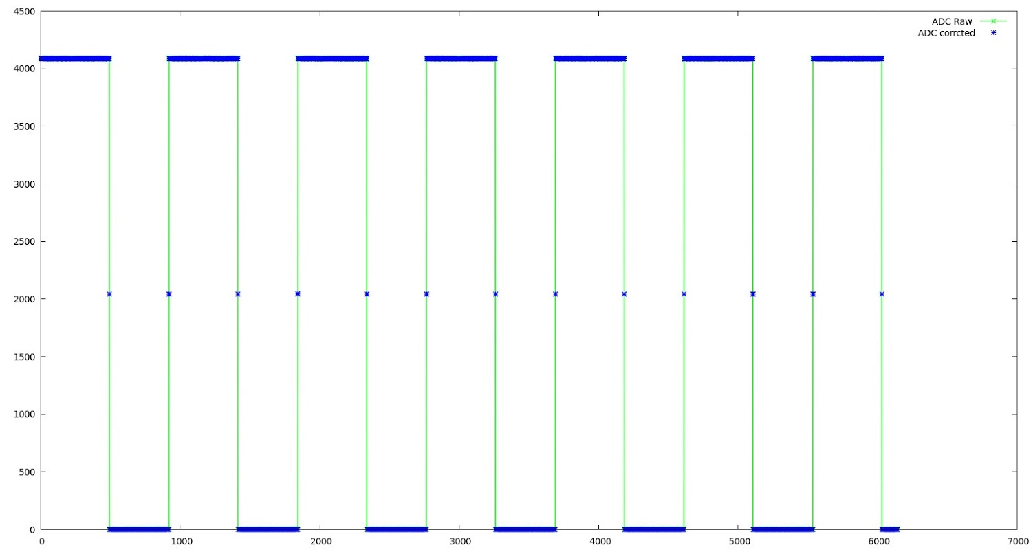
Plot of output (loop back PB0 [Pigscope TEST_WAVE_PIN] to PB1 [Pigscope analogInPin])
1) The RTC is powered, but has no crystal, so any attempt to read or set the RTC will result in the board locking up.
Solution: Fit the RTC crystal (or alternatively, don’t try to talk to the RTC).
.
Global variables use 55,152 bytes of dynamic memory.
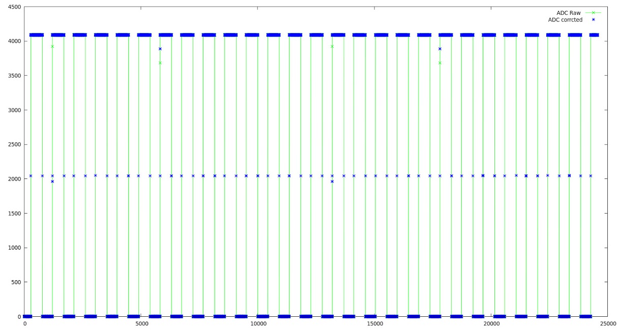
… which resulted in the plot above from the same test signal. ![]()
EDIT: The maximum number of samples I can squeeze into ram is of the order of 28K x 1024 # define maxSamples 1024*28
HOWEVER>>>>>
If I push things further, then bad things happen…
Flash page at addr: 0x08008000 erased

Flash page at addr: 0x08008800 erased2015-06-03T22:51:16

Flash page at addr: 0x08009000 erasedINFO src/stlink-common.c: Finished erasing 19 pages of 2048 (0x800) bytes

2015-06-03T22:51:16 INFO src/stlink-common.c: Starting Flash write for VL/F0/F3 core id

2015-06-03T22:51:16 INFO src/stlink-common.c: Successfully loaded flash loader in sram

write error, count == 1024

2015-06-03T22:51:16 ERROR src/stlink-common.c: run_flash_loader(0x8000000) failed! == -1
stlink_fwrite_flash() == -1
USB Status [unknown]
Waiting for tty device
should now be available.
1) The RTC is powered, but has no crystal, so any attempt to read or set the RTC will result in the board locking up.
Solution: Fit the RTC crystal (or alternatively, don’t try to talk to the RTC).
.
1) The RTC is powered, but has no crystal, so any attempt to read or set the RTC will result in the board locking up.
Solution: Fit the RTC crystal (or alternatively, don’t try to talk to the RTC).
.
(I wonder if the squint crystal will distort time in the vicinity ![]() )
)
Sketch uses 39,312 bytes (29%) of program storage space. Maximum is 131,072 bytes.

Global variables use 17,664 bytes of dynamic memory.http://www.aliexpress.com/item/48-pin-A … 43754.html
This is where I got several of this board, it can be a little frustrating, but I just love how easily it breaks out the IO.
attaches to my J-Link like a dream, which of course the maple mini does not, so I develop on this then implement on the other.
Saves a lot of wiring hell.
*edit* Note these boards use the STM32f103C8T6, slightly different chip that the boards above.
They are labeled on the back:
STM32FxCxT6 Board V5.02 (at least mine are).
Still, useful little blighters – slightly different layout again, there seem to be a lot of boards that are slightly different and yet
similar in this layout, which is in itself rather unique..
Despite all the gloom and doom in the STM datasheet about requiring a very specific RTC crystal, in light of my first success with the generic watch crystal from my junk box, I splashed out a buck on 10 more generic crystals (this was cheaper than buying one pucka crystal, with the STM spec, so worth the risk), and fired one on my other one of these.. These ebay crystals are probably smaller than you think, so a little care is needed to pre-bend the leads, and not sneeze while soldering them.
It seems to work perfectly well. Now all I have to do is figure out how to add a RTC battery, however having fired the board under the microscope, and scared myself with the size of track I need to cut, its proximity to the adjacent tracks, and the microsurgery needed to add the mod wire, I might just stick with the idea of powering the whole shebang from a large lipo, and setting the date on it manually every time the lipo goes completely dead.
For scale, on my monitor the picture above is roughly four times the size of the actual board, and I need to cut the track between the white capital “U” of “U1” on the silkscreen lettering and the small white dot below, next to pin 1… The hole needs to be approximately the size of the full stop at the end of this sentence, and needs to be bang on target. A bit of a tough job for my drill press ![]()
The rationale (besides my surgical cowardice) being that the STM32F103 will crap out and stop drawing power as the battery voltage drops, long before the RTC power domain dies, and the RTC will run on a lipo for months at a time, so there may not actually be an issue. Time for some experimentation I think. This time with big batteries, and you know how dangerous I am with small ones. ![]()
Just watch you don’t drain your lipo below its non return point.
PS.
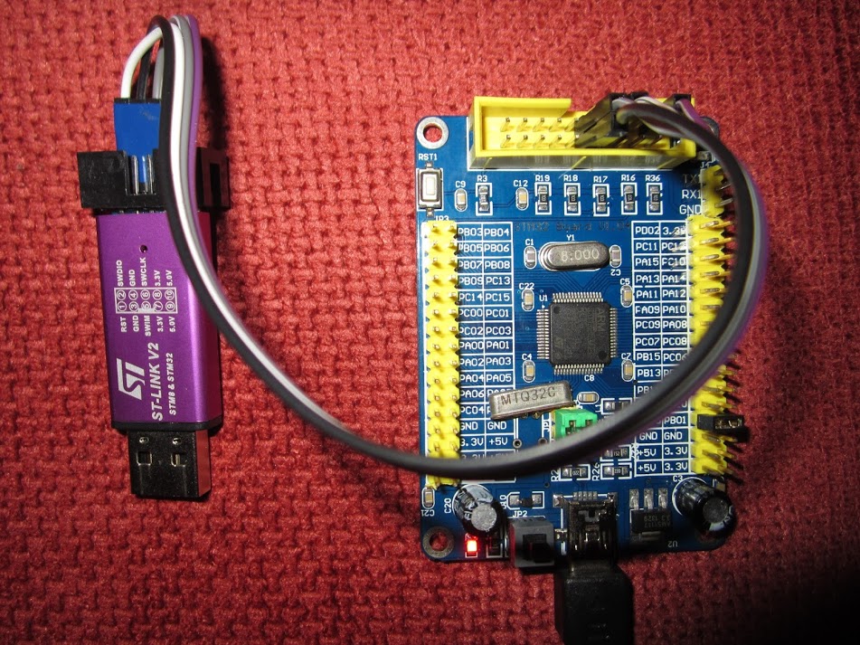
I can’t recall,… Does the bootloader work with that board ?
Just watch you don’t drain your lipo below its non return point.
I can’t recall,… Does the bootloader work with that board ?
Regarding battery draining, if you can set your sketch to put the MCU in “standby” mode, that is the mode that shutdown absolutely everything except the RTC domain, and should use only uA. the MCU will not wake up except with RTC, Reset, or Wakeup pin.
So you could set the board to standby and leave it like that for a long time, then press the reset button to power it up.
// Set PDDS and LPDS bits for standby mode, and set Clear WUF flag (required per datasheet):
PWR_BASE->CR |= PWR_CR_CWUF;
PWR_BASE->CR |= PWR_CR_PDDS;
// set sleepdeep in the system control register
SCB_BASE->SCR |= SCB_SCR_SLEEPDEEP;
// Now go into stop mode, wake up on interrupt
// disableClocks();
asm(” wfi”);
You need to include pwr.h and scb.h, like in the example sketch in the sleep thread, but I have been trying to get it to work in a maple mini, and I can’t get that thing to standby ever ![]()
I have doublechecked the registers with the ST standard peripheral library, and compared it to their function PWR_EnterSTANDBYMode in the peripheral library, and is exactly the same. I am puzzled as to why it wont work.
If you get a chance to test it, let me know. The MCU should reboot with the reset button or an RTC alarm, but in both cases it will act as a reset, starting from the reset vector and all.
It will still take a few mA unless you replace the voltage regulator, cause those 1117 are power hogs ![]()
In other words the new serial command “sleep” seems to put it to sleep, now perhaps we need to figure out how to set the RTC to wake it back up. ![]()
I haven’t figured out how to measure the current draw yet, I think a spliced USB cable with my multimeter patched in series in the +5V line and set on mA range may be simplest the way to do this.
EDIT: The RTC appears to continue to run while the processor is “sleeping”, so that looks promising.
If you have some bucks left (~3) (and further need for it!), then this could be your friend:
http://www.aliexpress.com/item/2015-new … 165.YQANRr
If you have some bucks left (~3) (and further need for it!), then this could be your friend:
http://www.aliexpress.com/item/2015-new … 165.YQANRr
Display device does not match the one in the photo.This device work properly. But instead of displaying power consumption it displays charging time. The device hasn’t memory of charging capacity. After power off it begins from zero. In the photo more interesting model than in reality!!!!!!!!!!!!!!!!!!!!!!!!!!!!! The limit mAh last sign and symbol not burn
Is there a resistor between tft-led pin and the led’s themselves?
Is the voltage configured for the led 5 or 3.3V?
What’s the normal voltage on a lipo battery?
What’s the normal voltage on a lipo battery?
I bought a STM32F103VET6 ( photo is to big to attach ) from ALI and it will really present a challenge!
The listing stated the the data would be sent by email.
Sadly this is not true.
The board is loaded with goodies, dual USB (/w 232) ports, BB RTC, two different NV storage chips, etc.
No documentation on anything short of the listing.
The only things that I have working at this point is the Stlink V2 upload and basic bitbanging.
Usart1 shows up on PA_9 but not at either of the connectors.
I have a large collection of SMC32 boards and will generally buy just about anything that I find interesting
but this one my prove to be past my limits.
Any ideas or tips will be welcome.
Thanks, + thanks for stm33duino
Bert
stephen
I bought a STM32F103VET6 ( photo is to big to attach ) from ALI and it will really present a challenge!
The listing stated the the data would be sent by email.
Sadly this is not true.
The board is loaded with goodies, dual USB (/w 232) ports, BB RTC, two different NV storage chips, etc.
No documentation on anything short of the listing.
The only things that I have working at this point is the Stlink V2 upload and basic bitbanging.
Usart1 shows up on PA_9 but not at either of the connectors.
I have a large collection of SMC32 boards and will generally buy just about anything that I find interesting
but this one my prove to be past my limits.
Any ideas or tips will be welcome.
Thanks, + thanks for stm33duino
Bert

