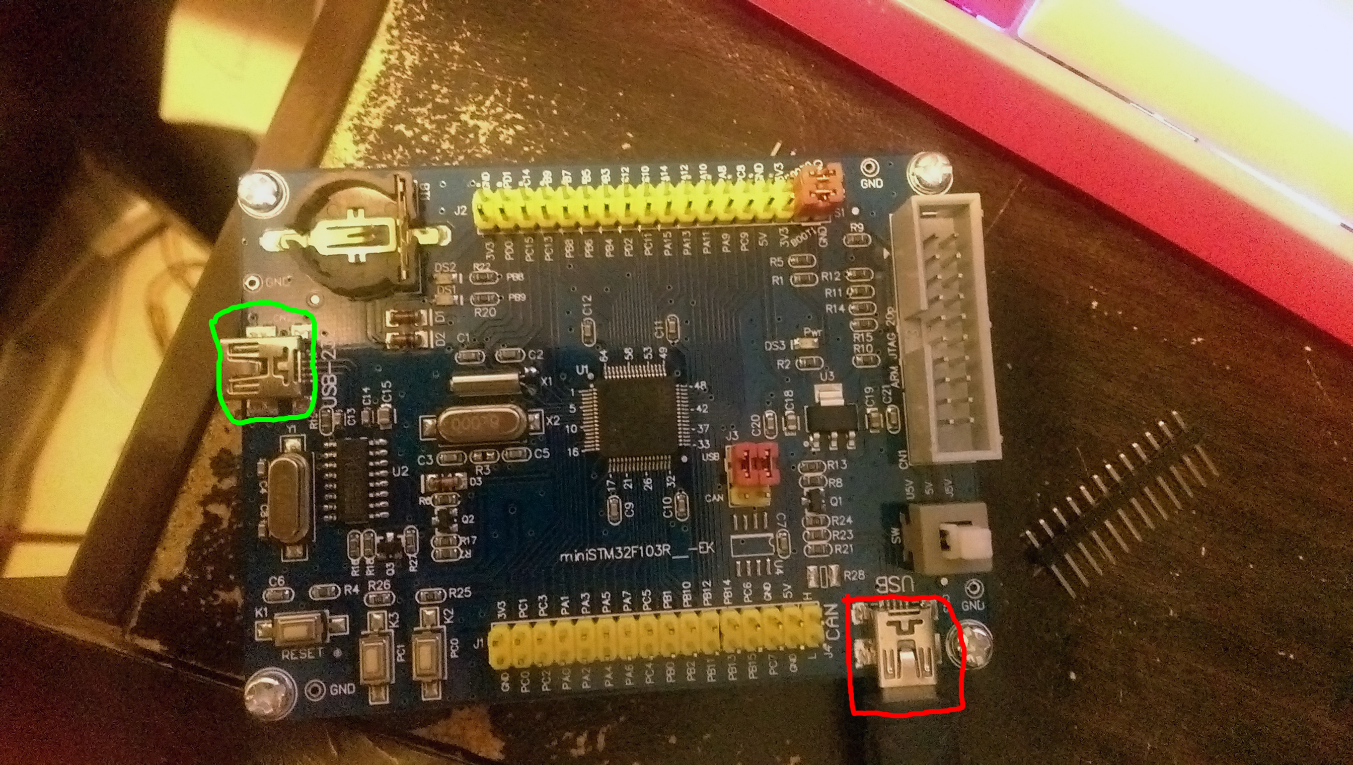
The device could be programmed either by an external USB to serial device, or by the built-in RS232 one as circled in green below, I’ve confirmed it by uploading blink sketches via both methods.
But I was unable to get the chip’s own USB (circled in red) to work at all, as in, on Windows, a new device does not appear in the “Ports” or “Universal Serial Buss controllers” trees in device manager, not even a new device with the yellow triangle warning message appears.
Just to be clear, the USB port was able to power the device, and the blink sketch that I’ve previously uploaded via serial still works under USB power, but the host computer cannot talk to the device at all.
I’m quite new to STM32 so I am really at a lost here, could someone help out?
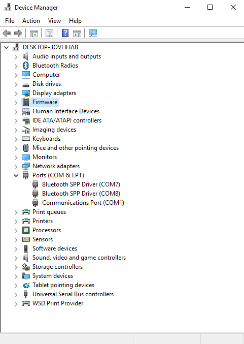
Below is a screenshot of my device manager with the device plugged in, I think I should make it clear, no new devices are detected at all when it is plugged in, there is no “new device is plugged in” notification sound when it is plugged in, it is as if the cable is only giving the board power but nothing else, I also tried several different cables and it made no differences.
Try following:
1. flash the bootloader (over the serial port PA9/10) – BOOT1 set to “1”.
2. use the “STM32duino bootloader” method when uploading blink sketch over the red USB port – (BOOT01 jumpers set to “0”). Now you should see COM port.
see
see
viewtopic.php?f=28&t=1877
For reference, I was able to get my bluepills working as per the instructions on the wiki, they appeared as “unrecognised devices” under device manager before everything was correctly configured but this generic board does not appear as anything at all under device manager.
And try to get the schematics..
i have vet & zet versions and istr putting or seeing something on the wiki.
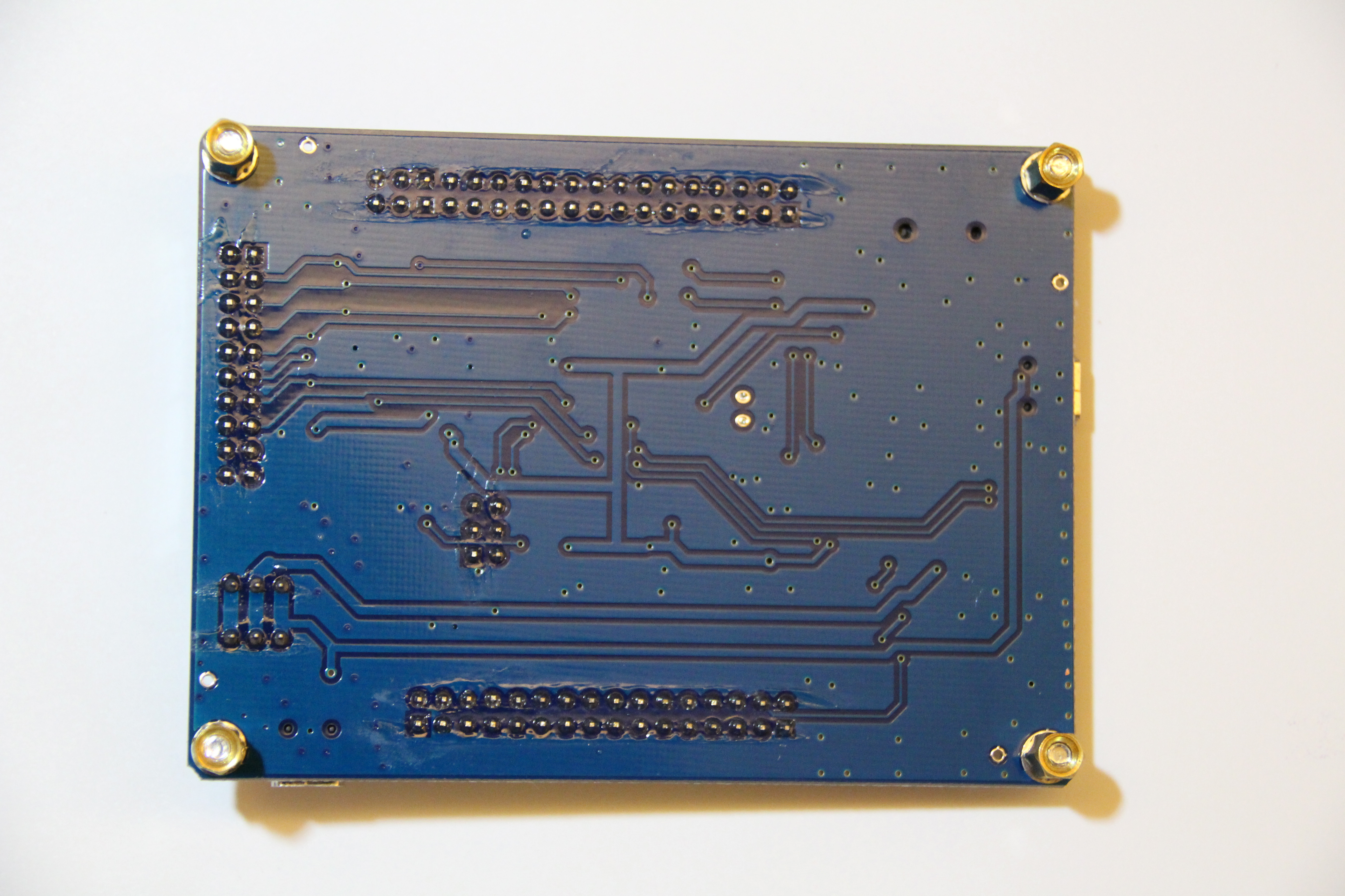
could you post top and bottom pictures?
any text to suggest maker or version ?
stephen
Btw, you should flash the bootloader when BOOT0 is set to “1”, not BOOT1!
BOOT1 should be always tied to GND.
the jumpers for boot0 and boot1 are ‘normally’ each in a line of 3 pins, the middle pin is the boot line.
‘o’ or gnd……..bootn……….. ‘1’ or 3v3
////|……………| link
‘o’ or gnd……..bootn……….. ‘1’ or 3v3
///////////// |……………| link
they were almost certainly set to the 0 side of those 3 pins originally
apologies if i’m teaching you how to suck eggs ![]()
![]()
![]()
![]()
stephen

BOOT1 is connected to PB2.
Now you know how and which pins you should control to flash the bootloader and upload further software.
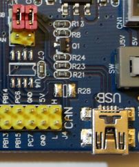
- usb part.JPG (22.37 KiB) Viewed 604 times
they’re both 3v3, that’s boot from embedded sram according to AN2606
boot1 boot0
X 0 user flash
0 1 system flash
1 1 sram
try moving boot0 to gnd or move both to gnd
if you have one, try using a stlink, well worth the £2 or so
the other red links (bottom right) appear to be set for usb, alternative is CAN on the right hand end of the bottom rows
the vet/zet variant has transistors q2, q3 associated with the serial interface, so try the board against that schematic for vct/vet
hth
stephen
The USB pins go PA11 and PA12, which are the right ones.
If PC7 is driven the wrong way it may be blocking USB communication. I dont remember how the pull up transistor is managed in the Maple (active high or low?), but I do believe in the code for Generic boards we don’t even try to use a pin for that functions, so it is probably left as input, in which case the transistor may or may not be leaving the pull up resistor connected. Unless the resistor get’s disconnected, the USB serial may not enumerate at all.
You could try in your sketch driving that pin low for a few ms, then high. And if that doesn’t work try the other way, driving it low, then high. I dont remember how long the pull up resistor needs to be connected, I believe it should be in response to some host action, but in practice I think the core just keeps it connected for set amount of time, try a ms or two.
Now, as far as the software. I think like someone posted before, that you may not be following the right process.
To get the USB serial detected you need to:
1.- Upload the stm32duino bootloader. At this point the board should show as a DFU device, but NOT as serial.
2.- Upload a sketch using the stm32duino bootloader. At this point the Serial USB should show up.
if it is a leaflabs maple style boards, i.e.
if the reset button and user buttons and leds is the same setup / connecting to the same pins as leaflabs maple
press reset and the user led should blink quickly 6 times
if this can be observed, it’d at least confirm that the bootloader is successfully installed and running properly
there is a strange feeling that either the boot loader isn’t correctly installed or that some errors cause the boot loader to crash on the board, there could be various hardware / software related reasons, e.g. HSE external crystal running at a different frequency or the board is wired differently etc
for the next part i’m only familar with linux,
in linux run lsusb
http://www.stm32duino.com/viewtopic.php … dfu#p25536
if you see 1eaf:0004 when running lsusb command this is the normal running mode (your sketch is installed and running)
if you see 1eaf:0003 when running lsusb that is maple in ‘perpetual bootloader mode’ ready to load the sketch
i’m not sure how to diagnose the same / tell if device 1eaf:0003 or 1eaf:0004 is connected, in windows, any suggestions?
found a useful link in windows (XP i think) , in device manager 1 could check the VID / PID of a device connected
http://xpenology.me/how-to-see-the-valu … pid-stick/
if no device drivers are hooked up, it would most likely show as an unknown device
seeing these vid : pid would confirm that (1) the bootloader is successfully installed and running (2) usb is working as expected
then the remaining parts is to figure out / install the windows usb driver stack and the config vid/pid so that windows can detect it correctly as usb-serial or dfu device

