Looking at the differences between the red board and the blue boards …
The red board:
Good things about the red board:
- 1.5k pull up resistor on the PA12 pin (USB D+) which you can programatically drag down for automated USB reset.
- large power capacitors and LDO power (AMS1117 3.3v).
Problems with the red board:
- Silk screen is barely readable, the text is chopped off on some of the pins
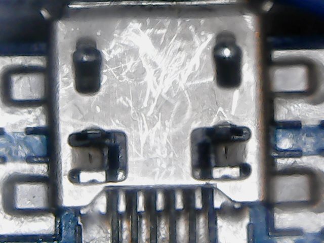
- USB connector only has two anchor points and it is directly soldered on the surface
- Small reset button with hardly any resistance
The blue board:
Good things about the blue board:
- Four soldered anchor point on the USB connector. What you can’t tell from this picture is that there is a notch in the pcb board and the USB connector sits down inside it some. This provides some lateral stability that takes some of the stress off the solder points. +2
(Actually there are now blue pills that have a two anchor point usb connector) - It has nice clear readable silkscreen printing. +1
- It also a larger reset button.+1
- Often supplied with a 300mV regulator (rt9193-33gb)
Problems with the blue board:
- Probably won’t work as a USB device if it has a 10k or 4k7 pull-up on PA12. You have to check the pull up on PA12 (USB D+). If it has a 10k or 4k7 pull-up resistor, you will need to replace it with a 1k5 one to use the native USB.
Nice features common to both:
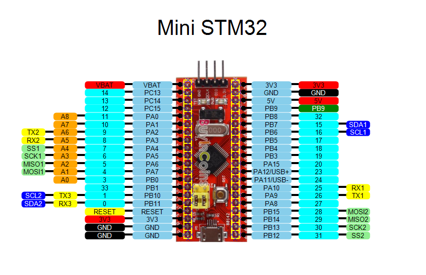
- SWD pins broken out and easily connected (VCC, GND, SWDIO, SWCLK)
- Multiple GND and 3V3 pins
- USB 5V is broken out with easy access.
- User LED on PC13
- Power LED
- You can probably use more flash (128k) than officially documented for the chip (stm32f103c8t6 64k), I was able to load 115k of flash on mine and it seemed to work.
- Both boards have the same pinouts, you can use them interchangeably
Problems with both boards:
- No preloaded maple bootloader * to me this isn’t really a problem as the entire 64k of flash is available for use. Also, every chip provides a factory ROM based serial boot.
- No user button
If people have any more comparisons or comments, please post on this thread.
viewtopic.php?f=28&t=37#p221
it seems that if you have a bad USB connector you have also a big LDO underneath.
I believe that big LDO meah high current.
Is there a difference on the bottom side between the red and blue one? I think i’ve already seen some with ams1117 as an ldo instead of the sot235 one (DEA1D if i can read it right, prop not)
~Straw
Red and blue seems identical in functionality.
I had to reflow solder the connector, both its electrical connections and also the 2 pads that hold it down ( or doesn’t )
But as I knew the repairs wouldn’t last, I got out my hot glue gun and completely smothered the connector and the end of the board in hot glue. I suspect epoxy resin glue would be even better, but it takes a while to set, ( even the 5 minute epoxy seems to take somewhat longer to fully set)
I’d advise anyone who has one of theses boards to put a load of epoxy over the USB connector, but make sure you don’t let it ooze inside the connector.

I still think the epoxy or Goop overcoat is not a bad idea. If you decide to use the DeoxIT product – “small amount” means to use very little! Whatever is in this stuff is concentrated. Using a lint-free lens cleaning cloth, one can actually see the dirt and oxide come off connectors! A film applied to DIP components assure easy insertion, excellent contact low-resistance, and ease of future removal, if necessary.
Ray
Connector failure because of bad design seems common loads of boards that I’ve seen, not just stm32
Just fixing into 2 small PCB pads causes the copper pads to be pulled off the board.
Actually it could also be the quality of the whole PCB. I managed to accidentally dislodge a reset button on a Zigbee programmer board a few months ago, and had to hand solder some tracks back into place.
So perhaps the copper is not well bonded to the fibreglass
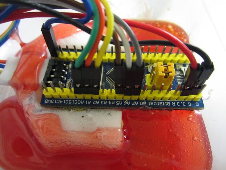
But once I have everything ready to go into Mr Pig, I suspect there will be a little more “hot snot” applied, particularly round the USB connector and anchoring the other wires.
But… Whatever works for you…… ![]()
But… Whatever works for you…… ![]()
(earth closet level indicator is still the most harmless thing that comes into my head at the moment….)
(earth closet level indicator is still the most harmless thing that comes into my head at the moment….)
Ray
Each board seems to have its strengths and weaknesses. The one thing I really like about the Red / Blue pill boards is the easy access to the SWD pins. However, I can’t really recommend any of those at the moment. I’m going to give one of those Baite Maple Mini’s a try next.
-rick
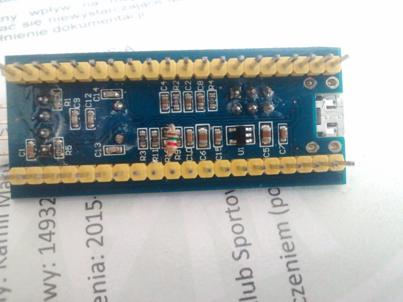
This is the underside of the problematic “Blue Pill” board:

I unsoldered voltage regulator?, marked (U1). I also unsoldered the 10k resistor connected to PA12 marked (R10). I have no idea why that was on PA12. Temporarily for testing, I just grabbed a through hole 1.5k resistor and just put it in place from PA12 to the 3.3v pin (see pic below). I then supplied external 3.3v power to the board from another “Red Pill” board. I had loaded up some blinky software on the blue pill so I plugged it in and pressed reset. It all worked. Feeling brave, I plugged in the USB connection on the Blue Pill. Even though it isn’t supplying the 3.3v the USBD+ and USBD- pins are connected and I watched it enumerate as /dev/ttyACM2 ( I had another board plugged in and it was using ACM0 and ACM2). When I pressed reset on the blue pill board, it dropped the USB connection and then enumerated itself again.
It seems like you can use this board with the native USB if you do some minor surgery. Just now, I loaded the ASCIITable example and it sent the data output to the USB Serial port. No chance I could confuse that as I’ve not soldered any pins on this board yet, so all it has is native USB. Worked fine. If I press reset on the “Blue Pill” board it drops the /dev/ttyACM2 device and my putty teminal emulator window exits. I can then connect again with putty to the new /dev/ttyACM2 and it works.
Here a “Hacked Blue Pill” is being programmed and debugged from a “Red Pill” running the BMP firmware:
- hack_blue_pill.jpg (201.81 KiB) Viewed 2738 times
So.. Where does this leave things
It sounds like the actual stm32 was not damaged.
Do you think that the USB reset code damaged your regulator(s) somehow
Or do you think that in your experimentation you could have damaged the regulator etc by doing something else other than just connecting to USB and having the board re enumerate by pulling PA12 low
Just a thought, but I wonder what the smallest reliable time we can drive PA12 low
I’ve tried dropping it down considerably from our original test values, and I suspect it can go even lower.
Actually I tested it much lower and it was ok on my PC.
E.g. If a 1 uS pulse is enough, its less likely to do any damage. (But I know this is a somewhat hacky approach and only something that people who are willing to take the risk should entertain if there is a definite risk of damage)
Thanks
I will re-instate the code when I get chance (later today) but it was better to be safe and remove it for a while
Cheers
Roger
Without any program uploaded, should the board enumerate or not if plugged into an usb port? Mine does not…
I was under the impression that the board would enumerate and would be programmable over usb.
I tried both windows 7 and linux. No luck
The bootloader for that board is
https://raw.githubusercontent.com/roger … 0_pc13.bin
I use STM’s own Serial Flash loader but if you don’t have that you could use stm32flash in the tools folder
Note, you need a USB to Serial converter to flash the board. It can also be done if you have a Uno (I posted how to flash using a uno elsewhere on the forum)
Flashing the bootloader via serial you need to set Boot0 link to HIGH
see https://www.youtube.com/watch?v=G_RF0a0hrak
For using a Uno see
http://www.stm32duino.com/viewtopic.php … &hilit=uno
What STM serial flash loader are you talking about? Is it a free download?
I tried stm32flash but no luck…
Just to be sure:
Boot0 should be 1
Boot1 should be zero
press reset
flash
correct?
Also, what baudrate do i need to flash? Is the default 57600 ok? is the default 8E1 ok?
I found the stm loader demo and burning the bootloader was successfull!
next… drivers
See driver/win folder
Run the bat file
If you are using Linux or OSX you need to make changes to the rules files, see the wiki on GitHub , it has information about this
BlinkNCount over usb is counting and blinking
No hardware modifications where necessary on my blue board.
OK. Some other people have already tested with Blue Pill and it works OK, it also works on Red Pill and for some people it works with the “Ugly” board, but the Ugly board doesnt work for me ![]() , perhaps mine has a fault
, perhaps mine has a fault
- bluepill.jpg (71.11 KiB) Viewed 2852 times
I hadn’t really looked at the voltage regulator on this board. * At first glance I thought it was a transistor *. I think people should replace the voltage regulator on “Blue Pill Board” (hereafter called) BPB. It seems to be under powered and leaves a lot to be desired.
-rick
I hadn’t really looked at the voltage regulator on this board. * At first glance I thought it was a transistor *. I think people should replace the voltage regulator on “Blue Pill Board” (hereafter called) BPB. It seems to be under powered and leaves a lot to be desired.
-rick
Been following the Blue Pill USB saga … have one of those with the 10K on PA12 as well.
I did the R10 (10K) resistor swap for a 1.5K but not much luck. Maybe the 3.3V supply on the Blue Pill?
Installed the “_PB13” bootloader via DFU & USB serial dongle, all OK. The Blue pill’s LED starts off flashing fast after reset and after a while flashes at a slower rate.
XP does recognize something gets plugged into USB but unfortunately the XP driver install tells me the install program is not a valid .EXE, so no drivers gets installed and I’m stuck there. On Linux, nothing gets enumerated (nothing listed with “lusb”). This is with and without the 10K resistor swap. Made no difference at all on Linux (Mint distro).
I’ve been playing with similar arrangements using ATTiny85 (VUSB), also DigiSpark that implements similar hardware for their Arduino bootloader. There the USB lines are limited using 3.3V zeners, also use the 1.5K resistor on D+ to VCC. With that hardware there is no issue regarding driving USB low (maybe Atmel chips have more sink capacity on I/O pins?). DigiSpark’s USB bootloader has an interesting enumerate workaround though… unlike Arduino modules, one do not connect the USB hardware until the Arduino downloader instructs one to plug it in. At that moment, and only then, the magic happens. DIgiSpark then enumerates and shows up as /dev/ttyACMx. Casually plugging DigiSpark into USB does not enumerate at all.
The USB feature is really not a big issue for me as the USB serial dongle works fine for me.
Thanks for all the efforts, all much appreciated.
Regards.
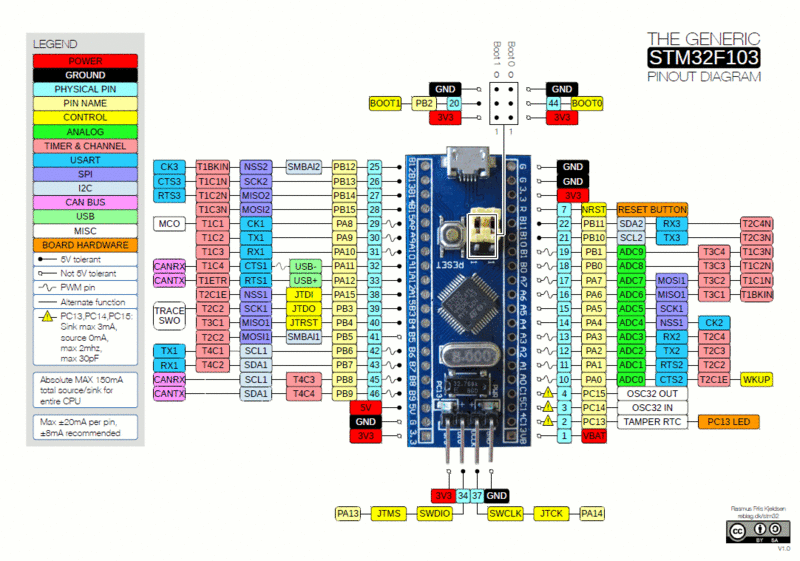
From the full bluepill schematic here… BluePill-6-STM32F103C8T6原理图.pdf
Thanks for the suggestion … indeed had my 1.5K connected to 5V and fixed now.
Shows up as “Bus 002 Device 006: ID 1eaf:0003” on Linux and Arduino download works fine too.
Regards.
http://www.stm32duino.com/viewtopic.php?f=3&t=699
Would appreciate input on this, as it had me quite confused (which isn’t that uncommon BTW 🙂
http://www.stm32duino.com/viewtopic.php?f=3&t=699
Would appreciate input on this, as it had me quite confused (which isn’t that uncommon BTW ![]()
Do BMP users want to use the BMP virtual serial as Arduino “Serial” or do they want to use USB Serial though the USB connector on the target board
If we enable USB serial in the sketch, it becomes “Serial” so the UART 1 connection to the BMP would become Serial1
Hence any debug text would go to a different place
However if BMP users would be willing to plug in 2 connectors, thats fine.
Personally, If I was using the BMP, I’d want “Serial” to be via the BMP as it would mean that the comm port was always open, as the BMP USB connection is not reset ever time the sketch is loaded.
Personally, If I was using the BMP, I’d want “Serial” to be via the BMP as it would mean that the comm port was always open, as the BMP USB connection is not reset ever time the sketch is loaded.
I treat the BMP as a debugger, and expect it to be minimally invasive. A “probe”, as the name says.
But the inability to use USB while debugging with the BMP is what actually threw me off.
When compiled with BMP, the code shrank by 5..6 KB, and using USBSerial gave me compiler errors.
Very confusing. Especially since it all worked when I was using an ST-Link, i.e. it included USB as expected.
Now try explaining to a newcomer what “Serial.print(123)” does. And how it depends on the “upload method” menu.
It seems to me that more people will start to use an ST-Link or a BMP once h/w debug becomes convenient.
Shouldn’t the behaviour be consistent, at least between an ST-Link and a Black Magic Probe?
I rest my case, pedantically 🙂 – part of the confusion is no doubt just me, but part of this is bound to trip up others.
-jcw
PS. Unfortunately, there also appears to be a re-build bug: switching to BMP first builds with USB, and then without, after an IDE restart. IOW, I see two different build results, without changing any settings – just an IDE restart. There seems to be an missed build dependency after a variant change, despite a message in the IDE to that effect.
Edit – fixed my comment above about trying to use USBserial.
Edit – fixed my comment above about trying to use USBserial.
There is a lot of history around USBSerial
We (well actually I ) got rid of its usage in the sketch, as it was non-standard.
When Leaflabs wrote the libmaple core, none of the AVR boards had onboard usb serial, so LeafLabs for some reason chose to call the serial over usb by a different name.
But in 2014 when I looked at it, in the light of the AVR Leonardo and the Due, it made more sense / more compatibility to map the Serial USB to Serial for the Maple mini.
I agree it can be confusing, that the upload method changes this, but I assumed that if you are using an external device to upload that inherently has serial i.e a Serial to USB converter or the BMP, then it makes sense to assume you are doing this for a reason and want to not use the onboard USB
The confusion is that the BMP does both. Its both a debugger and also has Serial USB.
STlink does not have USB Serial, so it made sense to enable it for STLink.
So, yes it can be confusing, but I suspect its because you are using the BMP ![]() if you were using STLink you’d not have noticed a conflict
if you were using STLink you’d not have noticed a conflict ![]()
<…>
So, yes it can be confusing, but I suspect its because you are using the BMP
I’ve flashed a Maple Mini with the 2.0 boot loader, and I can see the upload progress bars, but the code either doesn’t start, or the next upload doesn’t start, or the IDE loses track of the serial port (I’m on Mac OSX). This is after overcoming my confusion with BMP. So it’s been anything but smooth sailing for me so far. I’d really love to just be able to upload over USB.
But USB and the boot loader don’t seem to want to be friends with me!
I do have some hope that maybe November will be better…
-jcw
Try running the reset script manually, and see if the Maple mini resets
Ah. Another possible issue was the name of the TTY port. I can’t quite remember the details, but there was an issue with the TTY driver on OSX which we had issues with.
I recall needing to change something in STM32Flash as the TTY port was not getting called the correct name.
I will try to find a Maple mini with the new bootloader on it, and test with my 2 different Mac’s later, in case we now have a problem which we didnt use to have
Rick…. Would you mind if we enabled USB serial for BMP ?
Or can we just add an option for this via a menu, and default it to Off
I’m fine with that.
We’ll find out what @jcw wants when he wakes up in about 8 hours ![]()
I’ll PM you.
But what board are you using ??
A Maple mini or a Generic STM32F103C
If you are using a Maple mini board, but have selected the Generic STM32F103C option, its not going to work, because the USB reset stuff will not be correct for a Maple mini.
I have a feeling that what you are really asking for is the BMP option on the Maple mini.
But as we have tried to keep things as simple as possible for new users, the Maple mini does not that option.
If you want to use BMP on a Maple mini you’d need to add the upload menu from the Generic F103C to the Maple mini board section, in boards.txt, but you’ll need to remove the define for “Generic Bootloader” as this means actually tells the build process that your board doesnt have the Maple hardware and that it should reset the board via GPIO on the USB pin.
I know this name is somewhat confusing, and perhaps we should called this internal define by a more meaningful name, (and it could be changed), but what it really means is “Does not have maple USB reset hardware”
However thats a really long name.
For the BMP, I propose to enable USB for all upload combinations, at least across the Generic F1 boards – that’s what this GitHub pull request does: https://github.com/rogerclarkmelbourne/ … 2/pull/133
The Maple Mini entry assumes a boot loader, always. Most logical that way, IMO. If you want to debug it, I think there’s a way to do so with the generic F1 entries, which pulse PA12 for D+ control: at the start of setup(), add code to permanently enable the USB transistor on the Maple Mini via PB9, before calling “Serial.begin()”. Then, PA12 pulsing should work on the MM as well. This trick should work with all active USB control circuits (including the HY-TinySTM103 I’ve been doodling with, which uses PA0), now that PA12 pulsing has been invented and shown to work.
In short, for all generic F1’s: enable USB “Serial” regardless of upload method (github PR #133) and make PA12 pulse (already the case?). For individual boards with their own menu entry: keep options minimal for clarity (already the case?). Probably would be good to extend this to other Cortex types as well, I haven’t yet looked at those.
I’ll investigate further why the USB boot loader isn’t working for me, and report in a separate thread. It may well be Mac OSX related. BMP only works with gdb when using the /dev/cu.usb* devices and not /dev/tty.usb*, for example.
Thanks for all the comments and arguments. I apologise for the number and tone of my posts, if any sharp edges came through – it was definitely not out of disrespect, nor did I want to muddle this thread with unrelated issues!
-jcw
+cost 4$
+USB (Mini-USB better connection but rare cable)
+already soldered
+USB OTG (via connecting ID to gnd (need soldering))
+Good reset button (better than blue pills one)
+More Power Pins
+Good voltage regulator (LM1170 From 5V to 3.3V but 5V can be connected to any voltage)
+SWD + Serial pins on one side
+U can choose to have led or not, u can choose do u have USB connection of D+ and D-
+Easy to find docs (link on the board
-No LED on PC13 (on another pin or broken because of my try to turn it connecting 3.3v to it)
-can’t be installed on Breadboard/PCB
-No bootloader
-No 5V Regulator
Similar to http://www.stm32duino.com/download/file.php?id=17
Thanks !
The blue pill and the Maple Mini have basically the same micro on them (the extra 64k of flash is not relevant), with the same pinout and the same functionality, correct ?
Yet from the code I am seeing that if you do a digitalWrite(0, 1), different physical pins on the micro will be affected on the blue pill vs the Maple Mini. Am I correct about this ? Do the digital pin numbers map to different physical chip pin numbers on the blue pill vs the Maple ?
Hence there isn’t a board variant called “Blue Pill”, just “Generic STM32F103C”
The Arduino style pin numbers are only relevant to the Maple Mini and AFIK, Not to any other boards
If you have a Blue Pill (Generic STM32F103 ) board, you should use the real STM pin designations for GPIO, like PC13 etc
The real STM pin name is generally what is written on the generic boards
I would think this would make porting code from the Maple Mini to other boards easier, whilst having no disadvantage that I can see.
e.g. if you look at the enums they start with PA0 and work up to PC13 and above
I’ve no idea why the Maple mini has such a screwed up numbering order, I guess it was to aid the hardware PCB layout, as apart from that it doesn’t make a lot of sense.
But I see why Leaflabs originally use pin numbers and not pin names, as they were selling to buyers who were used to the AVR pin numbering, years before there were any third party Arduino boards, and even before boards like the RPi.
I actually find it hard to use the Maple mini, because it doesnt have STM pin numbers on it, and its harder to work out what pins have what functionality
I would think this would make porting code from the Maple Mini to other boards easier, whilst having no disadvantage that I can see.
what exactly do you mean by consistent?
Its the other way around
The Maple has the non standard numbering system, all the generic boards use the STM official numbering system.
I’ll see if I can figure out how to split postings into a different topic
-rick
<…>
But oh well, having the two resistors hanging a bit outside the board doesn’t bother me, and my board was never even meant to enter any beauty contests in the first place anyways!
http://wiki.stm32duino.com/index.php?ti … 103_boards
http://wiki.stm32duino.com/index.php?title=Blue_Pill
http://wiki.stm32duino.com/index.php?title=Red_Pill
Note. This is a work in progress, and not all details have been added for this board (e.g. no schematic or photo)
I will add the photo with pinout from this posting, but I’m not sure if they all have the same schematic.
I found a schematic for one STM32F103C8T6 board that had been posted to the forum, and it seemed to have the 32khz RTC crystal, but as far as I can tell my Red pill doesn’t have the 32khz crystal
PM me if you want to edit the Wiki, as I have to manually create accounts for the wiki as its totally separate from the forum and has its own database and user login etc
Edit.
The top 20 posters to this forum have been added as editors to the wiki, just do a password reset request with your login and you should get sent an email with instructions on how to reset / assign a password
Using a cheap/ebay st-link V2 and texane tool, I flash the bootloader in the Blue Pill, then with arduino IDE I upload a new program using USB. But I can do it only once. If I want to upload a new program, I must before do an erase with texane st-flash tool and flash again the bootloader. Then I can upload with usb again but only one time.
This is related to the 10K resistor or not?
If I need to replace the 10k resistor by a 1k5 one, which surface mount resistor size must I use?
Put it between PA12 and 3.3v
Please see the page in the wiki.stm32duino.coming the boards section
it seems that the dimensions of 1206, 0805 & 0603 are such that a 0603 will mount on 0805 pads and a 0805 will mount on 1206 pads, additionally 0603 will just mount on 1206
so it depends on what’s already there as well as what’s too hand.
stephen
i didn’t say it was neat, but 0805 overlaps on to 1206, as does 0603 ‘just a tad of overlap.!
think butt weld with solder.
if they’re 0603, replace or just stack a 1k8 on top.
stephen
I did some tests. The issue does not comes from the resistor. It is cause by usb connection. If I plug the usb cable to the computer screen, I can only upload one time. If I plug the usb cable to the computer box, no issue, I can upload many times.
It is the same with 10K or 1k5 resistor.
Also, did you select the serial com port for the board in the IDE and can you see serial data e.g from println()
Serial is used to reset the board, so if serial is not working it wont reset.
That being said, Some people have issues with specific usb ports on specific PCs and going through hubs etc.
Do you have another PC or Mac you can try it on
I also write a program with Serial.println(value++);, I was able to see in serial monitor the result.
But when connected to a usb port of the screen, no serial port is available. This confirm that issue comes from my connection to the screen.
I checked with an ohmmeter the resistor between PA12 and 3V3. The value is 10k04 exactly.
The USB spec value for this resistor should be 1.5k
This is a design fault on these boards ![]()
You can just solder a 1.8k resistor between PA12 and 3.3V as it will be in parallel with the exiting 10k that is on the board
As 1/(1/10000 + 1/1800) = 1525 ohms, which is close enough.
In fact, even 1.5k or 2k in parallel may fix this
But..
Running the board via a hub or a keyboard etc, is still likely to be problematic
Fist i want to say thanks for the information here and the wiki :
http://wiki.stm32duino.com/index.php?title=Blue_Pill
I have purchased the blue board and pinout is the same as in the wiki page.
Sadly I’m a beginner and it’s the first Arduino/ARM hardware i use and i have some problem.
I use Win7 as main PC when i connected the board in USB in my computer it display as unknown USB.
i have installed these repro driver :
https://github.com/rogerclarkmelbourne/ … er/drivers
now the device is named µPSD DFU STMicroelectronics Extension Application Demo with a yellow warning.
But DfuSeDemo.exe display nothing in the available DFU Device.
I have tried to add the 1,8K resistor in // but error is the same ( i have the 10K CMS resistor soldered).
After reading your discussion here , i think it’s normal beacause it don’t have the bootloader inside , so my computer can’t drive it yet.
i have downloaded “generic_boot20_pc13.bin” and seach a way to send it into the board.
I don’t have Serial USB cable but i have a JTAG USB Blaster clone.
Mayube i can build a DIY cable in RS232 ?
Is it possible to use OpenOCD and a JTAG USB Blaster for flashing the bootloader with these board ?
I use OpenOCD in my Raspberry for flashing Altera CPLD.
After that i think i will be able to upload new code directyly from USB into the flash ( after bootloader of course)
Thanks in advance
for information here is what dmesg display ( seems linux tells more information than windows ) :

<…>
for information here is what dmesg display ( seems linux tells more information than windows ) :
http://www.stm32duino.com/viewtopic.php?f=2&t=873
There is a section on windows problem, and a possible solution using zadig
Here is result with Zadig and Usb View!


Is it because they are no bootloader inside ?
i have buy this for send the bootloader.
very useful if you need to program both ends of an experiment.
these are just first couple for the search string ‘stlink programmer’
http://www.aliexpress.com/item/Hot-Sale … dfd54a9515
http://www.aliexpress.com/item/Hot-Sale … dfd54a9515
both £1.61
i’ll get corrected, but they use a protocol hardwired into the device, no bootloader.
if its just a small target board you can supply 3v3 at low milliamps, that’s 4 wires.
i usually power the target with a usb cable and connect just 3 wires, ground and the data/clock signals.
stephen
The board (MCU) is blank, you will need to flash the bootloader using a USB to Serial adaptor (or STLink etc)
Second, are the pins on the blue pill board 5V tolerant? Is there a list/schematic with those 5V pins?
The red “FT” indicates 5V tolerant pins.
Second, are the pins on the blue pill board 5V tolerant? Is there a list/schematic with those 5V pins?
I don’t really look into using the board for Arduino (F1 boards are just perfect for that), I’m more interested as using it as a flight controller with a custom firmware. I would like to swap the F1 CPU with an F3 for the floating point, and while I’ve read that the swapping should be pretty much pin compatible I decided to give it a try.
My only concern was some special cases I should look into with the swap.
But since from your answer looks like nobody did that I assume I’m kinda alone here and I’ll have to learn things the hardway…
Anyway, I’ll keep you up with the progress, thanks anyway, the info on this forum is awesome for me as a beginner. ![]()
Usually this board should be powered separately (from 5V or 3.3V) but I also want to connect over USB in order to access the board. Could this cause issues?
Usually this board should be powered separately (from 5V or 3.3V) but I also want to connect over USB in order to access the board. Could this cause issues?
Usually this board should be powered separately (from 5V or 3.3V) but I also want to connect over USB in order to access the board. Could this cause issues?
But I’m looking at the following documents:
https://storage.googleapis.com/google-c … 2_rev4.pdf
https://github.com/TauLabs/TauLabs/blob … y_v1.1.pdf
Both documents, top left corner. Is that the way I’m supposed to wire them?
after some search I found 3 different version of Blue Pill.
Version 1: 2 Anchor for USB, big components.
Version 2: 2 Anchor for USB, small components.
Version 3: 4 Anchor for USB, small components.
Does any one know the difference between them?
– The LDO of the first seems to be an AMS1117, with huge quiescent current, while the second use small LDO, probably such as SPX3819, with lower quiescent current.
– The MicroUSB connector of the first has only 2 mounting pad while the second has four, which make it more solid.
Initially there was a 10k ohm resistor.
I’ve replaced that resistor with a 1500ohm resistor (152) and I still get the same error (about malfunctioning).
When I supply power to the board (over USB) or via 3.3V then the PC13 led is blinking fast.
I’ve checked the resistance between PA12 and 3.3V and I have 1.5k now.
Do I have to write a bootloader first in order to be able to connect directly over USB to the board? Or the jumpers must be set in some other position?
1.) Use the built-in serial uploader with an usb->serial dongle (FTDI, CP210x, CH340 .. etc) and stm32flash
2.) Use Serial Wire Debug (SWD 2 wire JTAG) with an stlink programmer with openocd
3.) Load a bootloader using either method 1 or 2 and then use the bootloader upload. http://wiki.stm32duino.com/index.php?ti … bootloader
Dont know what is that…
Unsoldered the old chip with a tiny bit of bismuth alloy, cleaned then tinned the pads, cannibalized a 1500ohm resistor from another dead usb donor device, and soldered it with a light touch of the tip while holding the resistor on board with tweezers.
I also had a very big SMD for 1.5k resistor, but after I took the original resistor out, I feared the big sized smd will not fit on the tiny pads, so I started looking for a board for donors.
Anyway…
Using the Flash Loader Demonstrator, I was able to upload (boot0 set to 1, boot1 set to 0) a file generic_boot20_pc13.bin. I assume this is the right??? name for my board? Used a USB to Serial adaptor to do that.
After uploading it and moving the jumpers back (boot0 set to 0, boot1 set to 0) my computer is recognizing the board as a Maple DFU when I connect it over USB.
Now I’m stuck again, how to make it to look like a Maple Serial and not a Maple DFU?
If I try to rewrite a sketch, I can only do that on USB To serial Adapter, not on USB cable directly.
Help?
Select:
* Variant: STM32F103C8 20k RAM 64k flash
* Tools -> Upload method -> STM32duino bootloader
* keep pressed the reset button on bluepill board.
* Compile a blink sketch and click on arduino IDE “upload” button.
When you see the following message release the reset button.
- arduinoIDE.JPG (34.9 KiB) Viewed 1114 times
With the USB to Serial adapter, and proper jumpers(boot0 set to 1, boot1 set to 0) I uploaded file: generic_boot20_pc13.bin with the Flash Loader Demonstrator.
Then disconnected the USB To Serial cable and reconnected over the pure USB cable with default jumpers(boot0 set to 0, boot1 set to 0).
Now my blue pill was found as Maple DFU.
Then following Vassilis steps:
The bluepill must be connected to your computer USB socket.
Select:
* Variant: STM32F103C8 20k RAM 64k flash
* Tools -> Upload method -> STM32duino bootloader
* keep pressed the reset button on bluepill board.
* Compile a blink sketch and click on arduino IDE “upload” button.
When you see the following message release the reset button.
I managed to get then new USB Id device (Maple Serial).
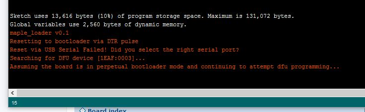
Warning: platform.txt from core 'STM32 Boards (STM32duino.com)' contains deprecated recipe.ar.pattern="{compiler.path}{compiler.ar.cmd}" {compiler.ar.flags} {compiler.ar.extra_flags} "{build.path}/{archive_file}" "{object_file}", automatically converted to recipe.ar.pattern="{compiler.path}{compiler.ar.cmd}" {compiler.ar.flags} {compiler.ar.extra_flags} "{archive_file_path}" "{object_file}". Consider upgrading this core.
Sketch uses 13,536 bytes (20%) of program storage space. Maximum is 65,536 bytes.
Global variables use 2,560 bytes of dynamic memory.
maple_loader v0.1
Resetting to bootloader via DTR pulse
Reset via USB Serial Failed! Did you select the right serial port?
Searching for DFU device [1EAF:0003]...
Assuming the board is in perpetual bootloader mode and continuing to attempt dfu programming...
Found it!
Opening USB Device 0x1eaf:0x0003...
Found Runtime: [0x1eaf:0x0003] devnum=1, cfg=0, intf=0, alt=2, name="STM32duino bootloader v1.0 Upload to Flash 0x8002000"
Setting Configuration 1...
Claiming USB DFU Interface...
Setting Alternate Setting ...
Determining device status: state = dfuIDLE, status = 0
dfuIDLE, continuing
Transfer Size = 0x0400
bytes_per_hash=270
Starting download: [##################################################] finished!
state(8) = dfuMANIFEST-WAIT-RESET, status(0) = No error condition is present
error resetting after download: usb_reset: could not reset device, win error: The system cannot find the file specified.
Done!
Resetting USB to switch back to runtime mode
<…>
Thanks guys!!! You are so awesome!
When I switch from STM32duino bootloader to serial and I try to upload the sketch I get this:
stm32flash 0.4
http://stm32flash.googlecode.com/
Using Parser : Raw BINARY
Interface serial_w32: 230400 8E1
Failed to init device.
When I switch from STM32duino bootloader to serial and I try to upload the sketch I get this:
stm32flash 0.4
http://stm32flash.googlecode.com/
Using Parser : Raw BINARY
Interface serial_w32: 230400 8E1
Failed to init device.
Don’t tell me is not possible for whatever reason like “that serial is running and can’t be erased during a reprogramming of a new sketch”. ![]()
If you use the usb cable then you have to select the stm32duino bootloader and the virtual COM port that is appeared on you device manager when you connect the bluepill to your computer.
If you want to send the compiled sketch to bluepill through your USB-to-serial adapter that is connected to the bluepill Serial 1 interface, then you select upload method : Serial.
Rapid Development w/ ArduinoIDE should utilize the bootloader – if 8K is an issue, you have the wrong uC.
After all fluid recompiles have been completed, you can remove the bootloader and go into a full-blown test cycle; noting numerous defects; correcting all issues in one edit session; then flash and retest. Do not recompile & flash again for something like a mispelled word – document.
We are not using coding sheets or punched cards: but IMO recompiles/reflashes just to get a lcd.locate(x,y) correct is an abuse of the methodology. Folks doing massive numbers edit/compile/reflash cycles sbould maybe investigate a PC based emulator.
Ray
I will also try to replace the CPU with a F3 instead of the current F1, but until I do that I was trying to familiarize with the F1 platform first, to know the weak points and the quirks, etc.
F1 is not really a big concern regarding the memory, however once I’ll upgrade the CPU on the board then the memory size will be probably my last concern. Later, if all is good I will try to develop probably my own board, but based on F4, in case nobody else comes with another F4 bluepill at a nice price or some other variant.
The only reason I want USB is because is one cable, one connector, I don’t have to mess with 4 wires like I do in the USB-to-Serial adapter. This is useful in a couple of situations
The only reason I want USB is because is one cable, one connector, I don’t have to mess with 4 wires like I do in the USB-to-Serial adapter. This is useful in a couple of situations
I will also try to replace the CPU with a F3 instead of the current F1,
<…>
Later, if all is good I will try to develop probably my own board, but based on F4, in case nobody else comes with another F4 bluepill at a nice price or some other variant.
Ray
I tried it some months ago, with bluepill #1 and stopped trying after reading everything about it on this forum and others.
Some days ago I picked up another bluepill from a friend and did the following:
– I removed the wrong resistor and soldered the proper 1,5kOhm in place
– The bootloader was already flashed on from an earlier attempt so
– I switched the jumpers and connected the pill with my computer via USB
– ENUMERATION WORKED, i was happy as fuck and flashed some sketches with Serial.print stuff in it and was happy that even the USB Serial thing worked!
– Then suddently enumeration stopped working and I was forced to use the DFU stuff instead. I remembered myself that lately Roger changed something in the bootloader in order to get the enumeration stuff working better, so I flashed the recent bootloader via Serial and from this point on not even DFU is working anymore and Windows keeps saying that something is wrong with the USB device…
– Flashing the “old” bootloader back on it didn’t help either.
– After that, I uninstalled and installed the maple drivers in every possible way and tried the Zadig approach – nothing.
Personally, I will just stop trying and use a Serial adapter instead.
<…>
The project includes a custom PCB and for this reason I designed a schematic part for BluePill. For designing I am using KiCAD (I am pretty familiar with it)
The part is included in _stm32.lib (hopefully more parts will added).
For PCB I am following DIP40 numbering, with this way the part can be used with the generic module, but latter I will design a more precise BluePill pcb module.
The seniors & grad students had access to the TSO room… I knew the work-student lady that managed access
Ray
<..>
is a blue/red/maple a deterministic(correct word??) system ? i did mech eng, not software eng at uni.
where might be the documentation describing the start up flow / mechanism of the stm32f103c8t6 be found?
stephen
i have received my ST link programmer.
With it i can sucessfully reprogram the Blue pill with the file : generic_boot20_pc13.bin
Now device is named : Mapple DFU in my device list.
Now i will try to use USB Dfu for reprogramming devices.
i launch DfuSeDemo but i can’t see any DFU device listed.
Is it because Mapple dfu use custom bootloader instead the ST one or maybe device can only be rewrited by serial ?
Thanks
here is the result

This mean the devices is been seen and showing the STM32duino bootloader.
Enjoy your new toys !
alt=1Now i can sucessfully upload over USB Dfu.
Sadly it seems that don’t works well.
I have made a simple blink led program.
-When i send it into adress 0x08000000 with ST link program works fine after a reset ( but rewrite bootloader).
When i send it with dfu-utils :
dfu-util.exe -d 1EAF:0003 -a1 -D led.bin
Bootloader launch ( led blink in high speed and after that turn off).
So it seems my user program don’t be launched.
Maybe it’s an adress problem ?
Sorry for question each day ^^
That way the IDE compiles the sketch at VECT_TAB_ADDR=0x8002000
Then you can use dfu-util.exe -d 1EAF:0003 -a2 -D led.bin to send the bin to the board.
I suppose you use Board: Generic STM32F103C series
http://www.st.com/content/ccc/resource/ … 161566.pdf
On the page 33/117 it is written:
PC13, PC14 and PC15 are supplied through the power switch. Since the switch only sinks a limited amount of current (3 mA), the use of GPIOs PC13 to PC15 in output mode is limited: the speed should not exceed 2 MHz with a maximum load of 30 pF and these IOs must not be used as a current source (e.g. to drive an LED).
However, all bluepills are using a led on PC13, is this a mistake from chinese designer/producer or I’m reading it wrong?
I had a blue pill with 10K pull-up. I uploaded the bootloader via USB-Serial adapter. After the 1.8K addition (in parallel), the USB enumeration and upload works flawlessly!
Initially, I followed the press-the-reset-button,initiate-upload,release-reset-button routine on Arduino. But it didn’t work and I spent some tense moments agonizing over UDEV rules in Linux. Then I tried uploading without pressing the reset button and it worked! ![]()
It seems the automatic reset through USB (through DTR?) is working now. It it a recent development?
It seems to depend on the USB hardware in your PC / Linux machine, and whether you go though a hub.
But you definitely need to put the 1.8k in parallel with the 10k, as 10k is far far higher than specified in the USB spec (which I think requires 1.5k – hence 1.8k in parallel, gives the correct resistance)
(Taken from: https://developer.mbed.org/users/hudakz … i/Homepage )
I really miss a blue pill in my collection and since they are 1.72 Euros (cheaper than a Nano 3.0) they is really no reason not to buy one
http://www.aliexpress.com/item/1pcs-STM … 20209.html
The only thing I see on the pics is the sub optimal minimal LDO (5>3.3V). Somebody knows how much mhA you can draw with it?
Another weak point of bluepill (except the error on USB resistor) is that there is no way to separate the USB supply from 5V plane (no diode attached)
I attached the photo of the type with the better LDO and big caps. Unfortunately you can’t ever know which type you will receive from chinese sellers…
I personally prefer plain boards without bootloader, (I prefer STLink for download) and for this reason (and the low price) I am still using BluePills. I also like all Nucleo boards from ST, as development boards for any STM32 variant (and get a Stlink V2.1 free).
I started with the STM32F103 nucleo board about 2 (or 3?) years ago, I have totally forgotten I own one
- mcp1702_hack.jpg (68.95 KiB) Viewed 870 times
Rick: I know this one use the small LDO, but take this as cure for everything:
http://www.aliexpress.com/item/S1065-Fr … 69056.html
0.03 Euros for one fire cracker is cheap enough
Rick: I know this one use the small LDO, but take this as cure for everything:
http://www.aliexpress.com/item/S1065-Fr … 69056.html
0.03 Euros for one fire cracker is cheap enough
I got these
http://www.aliexpress.com/item/50pcs-fr … 86579.html
0.04€/piece, I will experiment too!

And you had the camera handy as well ![]()
stephen
http://reblag.dk/wordpress/wp-content/u … iagram.pdf
Regards
Rasmus Friis Kjeldsen
http://reblag.dk/wordpress/wp-content/u … iagram.pdf
Regards
Rasmus Friis Kjeldsen
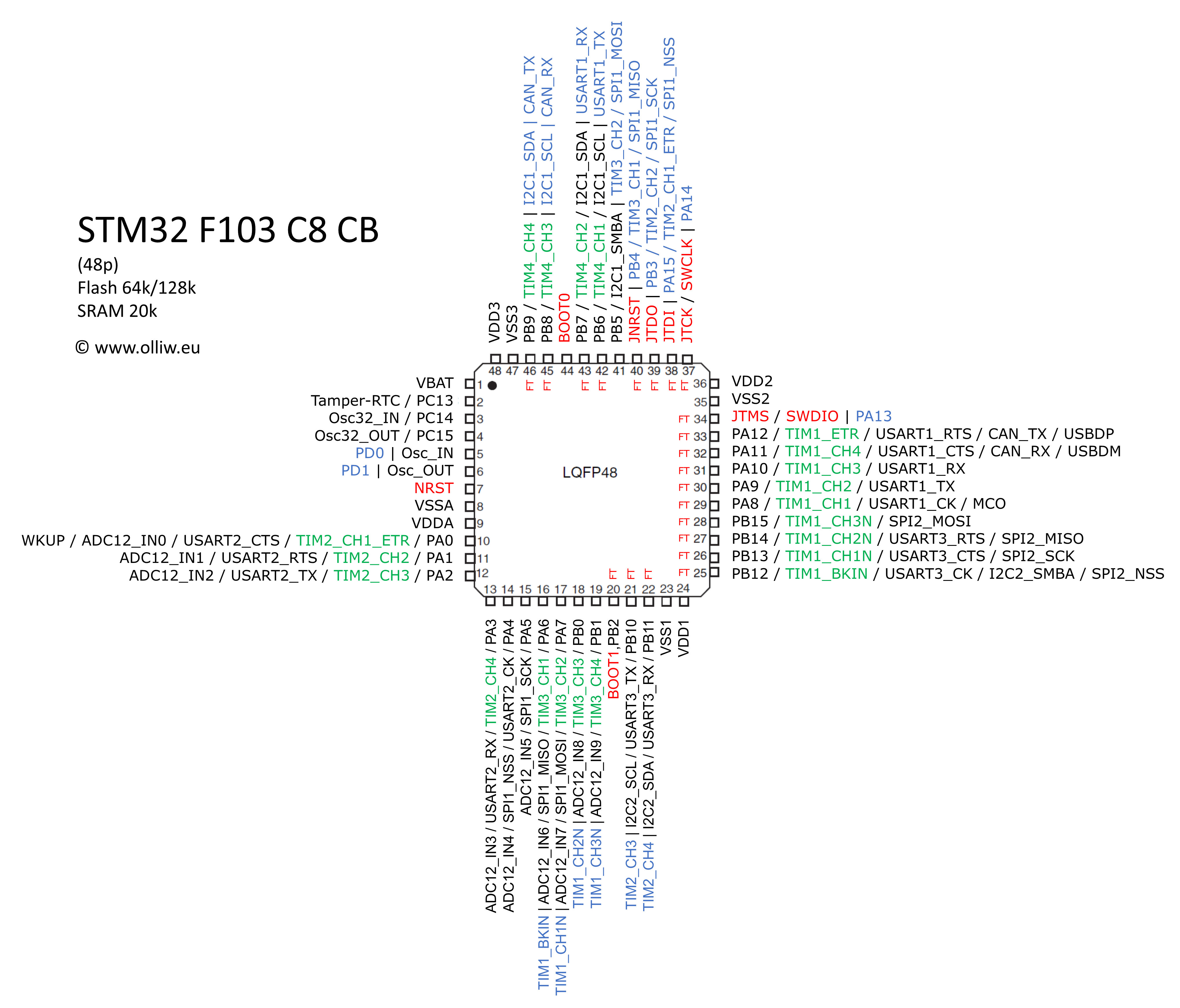
How about a webpage where you can search pins by e.g. port name? Simple javascript would highlight corresponding pin in the picture.
How about a webpage where you can search pins by e.g. port name? Simple javascript would highlight corresponding pin in the picture.
How about a webpage where you can search pins by e.g. port name? Simple javascript would highlight corresponding pin in the picture.
How about a webpage where you can search pins by e.g. port name? Simple javascript would highlight corresponding pin in the picture.
I took a short video with microscope of mine (with replaced R10) if anyone care to look ..
https://youtu.be/eAvqU8QzRwU
We have noticed that some “BluePill” boards have 10k resistors fitted, some have other values, so it looks looks like a “BluePill” is not always the same as the other BluePill boards that people have.
I don’t have any BluePill’s but I have some of the rare RedPill boards; however your board is different from my RedPill as well, (not just the colour).
It looks like the USB connector is different. It appears to be a micro USB but has 4 fixing points and also they seem to have a cutout in the PCB under the USB socket, so I presume its slightly recessed into the board.
https://youtu.be/eAvqU8QzRwU
It has got an 1k5 (the resistor close to B8) as the usb d+ pullup.
There is none 5V available on the headers..
BlackPill
I think I better order a few for testing.
https://www.aliexpress.com/item/Free-Sh … 44057.html
and 1.63 EUR if you buy 10pcs (registered mail – strongly recommended on ali!) : https://www.aliexpress.com/item/10pcs-l … 93738.html
The VBAT voltage preserves not only the clock but also some ram, which they call backup registers.
On boards where VBAT is hard wired to VCC then you will need to preserve VCC in order to preserve the clock and backup registers.
In a battery operated device, this can be done by putting the main processor to sleep, whereupon the power consumption drops to less than 1mA (considerably less if you implement this correctly and there are no other parts of your circuit, such as LEDs running).
This is not the best way to set things up, having a separate supply like a coin cell for VBAT is a better arrangement, but this is not possible on some boards due to the way they have been designed. If VBAT has not been hardwired to VCC, then you can add a coin cell to preserve the RTC and backup registers. If VBAT and VCC have been hardwired by the board design, then you must use other tricks.
Pin row to pin row it is 0.1″ wider than the blue/red pill boards. Overall it is 4mm longer and 2mm wider.
I’ll solder headers on and try to bootload it tonight if I can get the baby to sleep.
The VBAT voltage preserves not only the clock but also some ram, which they call backup registers.
On boards where VBAT is hard wired to VCC then you will need to preserve VCC in order to preserve the clock and backup registers.
Pin row to pin row it is 0.1″ wider than the blue/red pill boards. Overall it is 4mm longer and 2mm wider.
I’ll solder headers on and try to bootload it tonight if I can get the baby to sleep.
It seems to have a better USB connector than the BluePill in that it has through hole soldered pins holding it in place.
The downside of this board, is that the rows of pins are even wider apart than the BluePill so make it harder to use on a breadboard.
I installed the bootloader using STLink, but need to build a version that flashes PB12 as we don’t currently have one with that config
Unfortunately at the moment I seem to have some build issue, I’m not sure if its a compiler version problem, as my default compiler is 4.9.3, but the IDE uses 4.8.3, so I think I better try going back to that version and confirm why any new bootloader I create doesn’t seem to work correctly ![]()
Looks like the bootloader will not compile correctly with GCC 4.9.3 . Its probably the optimisation which is causing the problem
(I should have read my own ReadMe, as its listed in there that 4.9.x doesnt work. I am sure it can be bug fixed, as its probably one of the hardware addresses for the USB registers needs to be declared as volatile, but I don’t have time to bug fix this at the moment)
So I’ve changed my default arm compiler back to 4.8.3 and compiled a new version of the bootloader for the BlackPill
The bootloader can be downloaded from github, here https://raw.githubusercontent.com/roger … 0_pb12.bin
If I get time I’ll also make a bootloader for the HYTiny STM32F103T, as I suspect the reason I could not make the bootloader work on that board may also have been the compiler version issue.
The downside of this board, is that the rows of pins are even wider apart than the BluePill so make it harder to use on a breadboard.
I request your help about the STM32 blue pill board.
I the beginning of this thread i have buyed one and you helped me for installing the bootloader (page 9).
with this board i have sucessfully completed my project an USB HID Sega Megadrive Cartridge Reader :
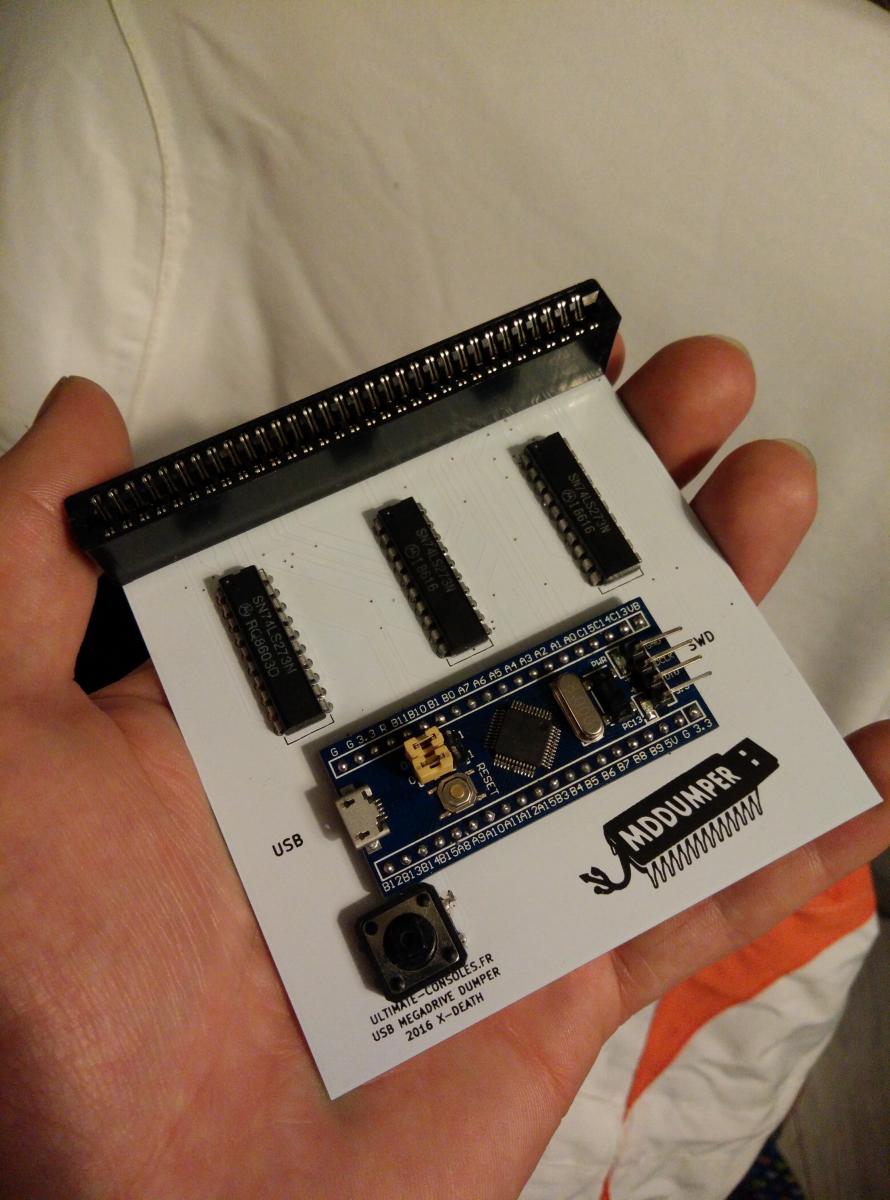
https://github.com/X-death25/STM32_Proj … adrive_HID
But i have buyed a pack of ten STM32 Blue pill on Aliexpress and when i solder these board on my PCB the USB enumeration fail…
i can hear the “usb fail sound”.
it works just well with the same binaries on another blue pill board..
Strangly it’s works fine with an old computer under Windows XP
i have tested a 1,8K resistor in parallel of PA12 & VCC3 but without sucess…
here is a picture of usb view
I don’t understand were is the problem , the pcb and binaries is OK because it works with my first blue pill…
Could you help me ?
Also, you should first erase the whole flash and then burn the STM32duino bootloader.
It should work after these steps.
Usb serial should work if you use srm32duino bootloader method.
But when it’s switch onto my own program the USB HID don’t works…
I have noticed that the CDC Serial does not wait for connection like it does on the Leonardo though, if I do the usual:
 while (!Serial)

;
while(!Serial.available());while ( !Serial.isConnected() ) ;@stevestrong: That works fine, thanks! But then this is a deviation from the Arduino API, why?
@stevestrong: That works fine, thanks! But then this is a deviation from the Arduino API, why?
PR submitted: https://github.com/rogerclarkmelbourne/ … 2/pull/270
USB serial, GPIO, SPI (with DMA) is working out of the box.
Many libs can be shared between F1 and F4.
For example, almost 2 years ago, I’ve done lot of things with Netduino2Plus.
Networking, SdFat, LCD shield, etc…
STM32F103C8T6, STM32 ARM Cortex-M3 Minimum System Development Board
http://s.aliexpress.com/vyAfIjUB
(from AliExpress Android)
I have an arduino mega ( 2560) from them and it is well made, the price is too high compared to the others boards
[aster – Sun Jul 30, 2017 10:50 pm] –
New contender in the war:
STM32F103C8T6, STM32 ARM Cortex-M3 Minimum System Development Board
http://s.aliexpress.com/vyAfIjUB
(from AliExpress Android)I have an arduino mega ( 2560) from them and it is well made, the price is too high compared to the others boards
as noted in this thread about somewhat pricy stm32f103 source prices (from st itself)
http://www.stm32duino.com/viewtopic.php?f=3&t=2359
there is this lingering speculation that perhaps even bluepill itself may no longer be as cheap as it used to be at some point
Yesterday, I received an order of 5 Blue Pills recently purchased from ebay. The price is still about the same ~$2USD. The latest ones look exactly like the ones I purchased more than 2 years ago. They still have the wrong resistor on R10, the smallish voltage regulator, and the notch for the four pad usb connector nestled in the notch on the pcb. I still don’t see a schematic online that actually represents the board I purchased. This one comes closest, however it shows a 4k7 pullup resistor connected to 5V for PA12/USBD+ The pullup should be 1k5 and connected to 3v3.
All in all still pretty amazing, that we can buy such a powerful ARM chip and thanks to all the effort by people here it is useful with the Arduino IDE. Thanks everyone!
It does seem or be cropping up more and more in videos and blog posts and other articles.
In the last week, 2 posts on Hackaday have used the BP, neither of which were using it with the Arduino IDE.
The week before, I noticed someone using it to replace a cypress chip, to make an open source signal generator , which goes up to 4GHz.
I was contacted a few months ago about doing a special version of the core for the ZumSpot HAM radio system ( just needed a minor flow control change on USB serial )
And the list goes on and on.
Only until I read this post that I realised that all the red pills are gone from the market..
I will probably use up all the red pill with point to point wiring and move forward to go with the blue pill after that …
[Rick Kimball – Sun Aug 06, 2017 3:16 pm] –
All in all still pretty amazing, that we can buy such a powerful ARM chip and thanks to all the effort by people here it is useful with the Arduino IDE. Thanks everyone!
It’s also amazing that you picked that name to differentiate them, and has pretty much become a brand for the board, even ebay sellers use that name:
http://www.ebay.com/itm/STM32F103C8T6-A … 2145343898
Had you trademarked it, you could be get rich just with royalties and fees ![]()
[stanleyseow – Sat Sep 16, 2017 1:00 pm] –
I will probably use up all the red pill with point to point wiring and move forward to go with the blue pill after that …
The red pill and blue pill use the same pinouts. You shouldn’t have to do anything. They are completely interchangeable.
The red pill and blue pill use the same pinouts. You shouldn’t have to do anything. They are completely interchangeable.
Thanks .. I just notice that they are the same pinout, so for the Blue Pill, I will have to do the “R10” operation like before ??
Here is the picture of the red pill with my version of MMDVM HAT …
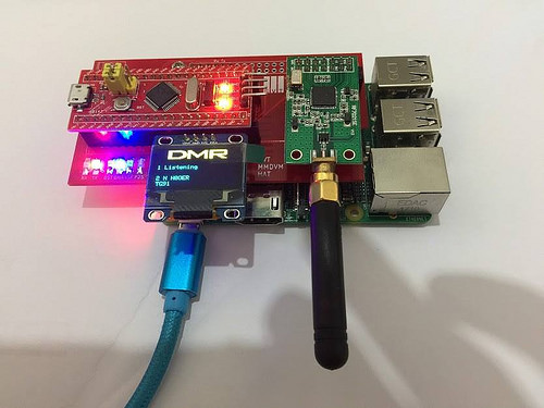 SVT MMDVM HAT by stanley_seow, on Flickr
Thanks a bunch
AFIK they are functionally equivalent to the Blue Pill
A better option now seems to be the Robot Dyn version which has a black coloured PCB, and has the correct USB pullup resistor (unlike the Blue and Red pill which both have the incorrect resistor resulting in USB connection issues for some people)
[Rick Kimball – Sun Nov 12, 2017 9:56 am] –
roger the pull up on the red pills are fine.
Thanks…
All my red pills have broken USB connectors, so I am still not sure if they are worth buying unless they now use a stronger usb connector
I’ve been ordering only the 4 pads ones.
The 4 pads ones come in two variants:
1. soldered to the pcb – sometimes not well enough
2. weakly soldered, the mechanical connection to the pcb done by pressing the fins into the mounting holes and soldered with a tiny amount of solder.
As the microusb connectors create a much bigger insertion force on the socket (in comparison with mini usb used in MM) the 4 pads in both 1. and 2. need to be resoldered with a large blob of tin such the pads and the adjacent body (the walls) of the socket are covered by the tin.
That improves the mechanical and electrical durability.
- Sun Nov 12 13-07-03.jpg (56.58 KiB) Viewed 604 times
[RogerClark – Sun Nov 12, 2017 10:48 am] –
All my red pills have broken USB connectors, so I am still not sure if they are worth buying unless they now use a stronger usb connector
That is exactly the problem. It also the reason I penned this redpill vs bluepill post in the first place. I have 5 red pills with perfectly good pullup and usb connectors that have snapped off : (
I do the same thing… Solder the BluePill through holes on the connector to make it stronger
Naked-eye I couldn’t see any solder, but under a microscope it looks like the hole is well-filled with solder around the fins.
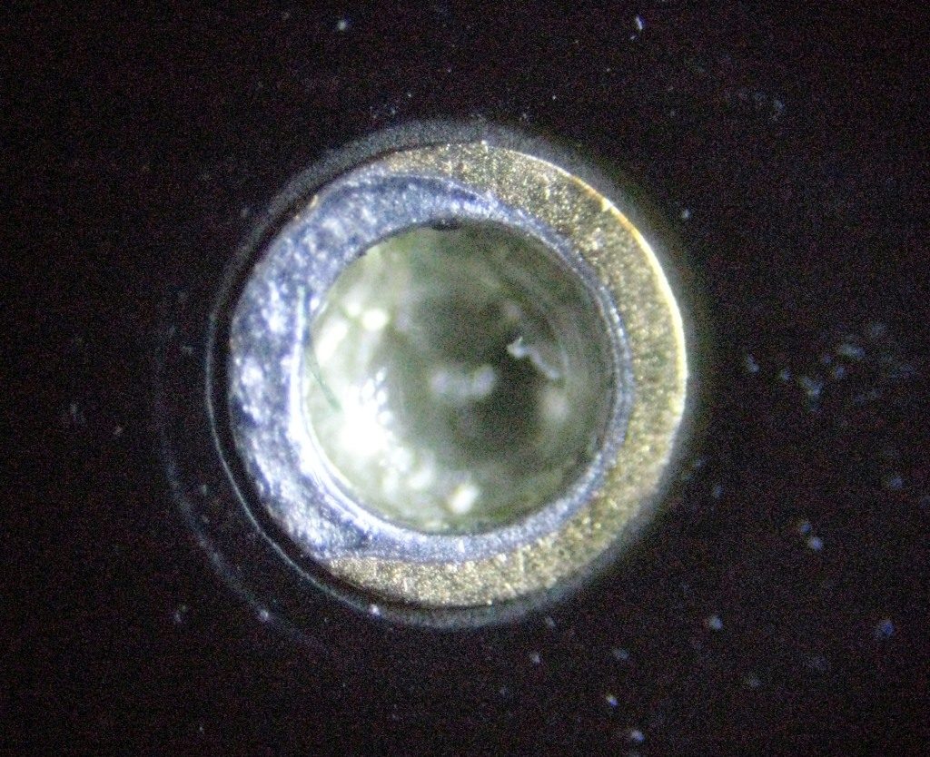
- innerpin.jpg (226.47 KiB) Viewed 985 times
Robot Dyn or someone else ?
[RogerClark – Mon Nov 13, 2017 1:04 am] –
Which Black Pill ?Robot Dyn or someone else ?
Someone else. It looks just like this one.
[RogerClark – Sun Nov 12, 2017 9:02 am] –
I’m not sure why you would want a Red Pill, apart from the colour.
AFIK they are functionally equivalent to the Blue PillA better option now seems to be the Robot Dyn version which has a black coloured PCB, and has the correct USB pullup resistor (unlike the Blue and Red pill which both have the incorrect resistor resulting in USB connection issues for some people)
Roger, I was just interested to see how many vendors were selling these and what the quality looked like on them compared to the blue and black pills. So now it looks like the black pill from RobotDyn is the best quality one out there? I appears to have the same pinout as the BP, is that correct? That would be nice as it would give 2 different sources for these. What are your thoughts about this Black Pill vs the Baite Maple Mini clone with respect to quality and long term viability as I am still contemplating using one of these in my commercial product?
Thanks again
[RogerClark – Sun Nov 12, 2017 9:02 am] – A better option now seems to be the Robot Dyn version which has a black coloured PCB, and has the correct USB pullup resistor (unlike the Blue and Red pill which both have the incorrect resistor resulting in USB connection issues for some people)
The one downside of the Robot Dyn black pill over the other options (black pill, red pill, PB12-LED black pill) is that you can’t avoid paying shipping, so if you’re ordering just one, it costs about a dollar more. If you’re going for larger quantities, it’s not a big deal. I do like how it exposes more pins than the PB12-LED black pills.
I also paid for ePacket (which worked out to be about a dollar extra on each one.
I still think they are good value, and at least I’ll get them before Christmas
The shipping fee to Germany (china packet plus) is only total 40 cent extra.
Robot Dyn will be offering 2 additional versions of this board from next week
One has our bootloader on it and I think the other version has some other firmware or bootloader pre-installed.
They did not say if the price was different
[RogerClark – Tue Nov 14, 2017 2:47 am] –
I still think they are good value, and at least I’ll get them before Christmas
Right after 11.11, I kind of doubt it.
[evildave_666 – Tue Nov 14, 2017 11:23 am] –[RogerClark – Tue Nov 14, 2017 2:47 am] –
I still think they are good value, and at least I’ll get them before ChristmasRight after 11.11, I kind of doubt it.
Hopefully, as I specifically paid for postage, I my packet my be put a bit higher on the pile that get scooped onto into a container ship


All Comments