http://henrysbench.capnfatz.com/henrys- … er-manual/
I can see the digital pinouts change etc, not sure if the description of the pinouts is accurate.
Currently I’m using D17(A), D18(B) and D19 (buttton).
The board has inbuilt pullups and I’m using 3.3v .
Is it a hardware problem or a software?
http://www.stm32duino.com/viewtopic.php?f=18&t=15
regards
Matthias
Sotimes detents equals pulses, sometimes not.
Some types will snap on phase “B” so you cannot assess.
Some time ago I ordered a couple of cheap chinese EC11, absolutely crap!
Sometimes they generate one pulse, sometimes two, sometimes not.
ALPS encs are much much more expensive..but they are preserving heart attacks ![]()
http://www.stm32duino.com/viewtopic.php?f=18&t=15
regards
Matthias
(I used the the click encoder library as it has debounce, double press and long press).
https://github.com/0xPIT/encoder/tree/arduino
I move the pin A and Pin B output to 18 and 19 (pb 4, pb3) because they are meant to be 5v tolerant pins.
The board has its own 10K pullups.
but on 3.3 and 5v I get no reading at all, with any library, or code snippet.
on the Mega it works perfectly.
Its possible that the Logic low from that device is only something like 1.8V which would be a logic low on a 5V system buy still a logic high on a 3.3 V system
In this case, I doubt this is the problem, but as these devices are normally mechanical, I dont know why you dont run it from 3.3V, or alternatively use a resistor divider network to correctly change the 5V logic levels to 3.3V
Use of 5V peripherals is in my experience no longer the norm for most modern MCUs.
Its possible that the Logic low from that device is only something like 1.8V which would be a logic low on a 5V system buy still a logic high on a 3.3 V system
They could use the Analogue input, but I’m not sure if its 5V tollerent (probably not) so they’d need a voltage divider
They could use the Analogue input, but I’m not sure if its 5V tollerent (probably not) so they’d need a voltage divider
They could use the Analogue input, but I’m not sure if its 5V tollerent (probably not) so they’d need a voltage divider
struct EncoderSetings {

uint8_t PinA;

uint8_t PinB;

uint8_t PinC;

uint8_t Min;

uint8_t Max;

uint8_t GreyCode;

uint8_t mutePin;

volatile uint8_t Val;

bool GoingUp;

bool GoingDown;

volatile bool IsDirty;

bool muted;
} ;
void ScanEncoder(EncoderSetings &ThsEnc)
{
uint8 OldGreyCode;
//hostSerial.println("Reading the encoder... press a key to abort.");
if (digitalRead(ThsEnc.mutePin)==LOW && !(ThsEnc.muted)){
// mute pressed
ThsEnc.muted= true;
ThsEnc.IsDirty = true;
RotaryIsDirty = true;
}
{
OldGreyCode = ThsEnc.GreyCode;
ReadGreyCode(ThsEnc);
if ( ThsEnc.GreyCode != OldGreyCode)
{
// "Forward" is shown by the position going from (0 to 1) or (1 to 3)
// or (3 to 2) or (2 to 0). Anything else indicates that the user is
// turning the device the other way. Remember: this is Gray code, not
// binary.
if (OldGreyCode == 3) { // Starting Rotation
ThsEnc.GoingUp = ((ThsEnc.GreyCode == 1));
ThsEnc.GoingDown = ((ThsEnc.GreyCode == 2));
}
else
{
if (ThsEnc.GreyCode == 3) { // Ending Rotation
if ((ThsEnc.GoingUp) && (OldGreyCode == 2)) {
if (ThsEnc.Val < ThsEnc.Max) {
ThsEnc.Val++;
ThsEnc.IsDirty = true;
RotaryIsDirty = true;
}
}
if ((ThsEnc.GoingDown) && (OldGreyCode == 1)) {
if (ThsEnc.Val > ThsEnc.Min) {
ThsEnc.Val--;
ThsEnc.IsDirty = true;
RotaryIsDirty = true;
}
}
ThsEnc.GoingDown = false; // Back In the Parked Position
ThsEnc.GoingUp = false; // Back In the Parked Position
}
}
// debounce the pot
// if ((ThsEnc.GreyCode!=OldGreyCode) && (OldGreyCode=3)) _delay_ms(10);
if (ThsEnc.muted ) {
ThsEnc.muted=false;
ThsEnc.IsDirty = true;
RotaryIsDirty = true;
ThsEnc.GoingDown = false; // Back In the Parked Position
ThsEnc.GoingUp = false; // Back In the Parked Position
}
}
}
}
void SetupEncoder( uint8 Index, uint8 PinA , uint8 PinB, uint8 PinC, uint8 mutepin, uint8 Min, uint8 Max, uint8 Val )
{
Rotary[Index].Min = Min;
Rotary[Index].Max = Max;
Rotary[Index].PinA = PinA ;
Rotary[Index].PinB = PinB;
Rotary[Index].PinC = PinC;
Rotary[Index].mutePin = mutepin ;
Rotary[Index].Val = Val ;
Rotary[Index].GoingDown = false ;
Rotary[Index].GoingUp = false ;
Rotary[Index].IsDirty = false ;
Rotary[Index].muted = false ;
ResetPins(Rotary[Index]);
ReadGreyCode(Rotary[Index]);
}
void ResetPins(EncoderSetings &ThisEncoder)
{
// Rotary encoder input lines
// Configure as input, turn on pullup resistors
pinMode(ThisEncoder.PinA , INPUT_PULLUP );
pinMode(ThisEncoder.PinB, INPUT_PULLUP );
pinMode(ThisEncoder.mutePin , INPUT_PULLUP );
pinMode(ThisEncoder.PinC, OUTPUT );
digitalWrite(ThisEncoder.PinC, LOW);
}
void ReadGreyCode(EncoderSetings &MyEncoder)
{
MyEncoder.GreyCode = ((digitalRead(MyEncoder.PinB) * 2) + digitalRead(MyEncoder.PinA));
}
bool RotaryHasChanged(uint8_t &Ind)
{
return Rotary[Ind].IsDirty;
}
uint8_t ReadRotaryValue(uint8_t &Ind)
{
Rotary[Ind].IsDirty = false;
if (Rotary[Ind].muted) return 0;
else return Rotary[Ind].Val ;
}
void ScanAllEncoders() {
for (uint8_t index = 0; index < EncoderCount; index++ ) {
ScanEncoder(Rotary[index]);
}
}
bool ARotaryHasChanged()
{
if (RotaryIsDirty)
{
RotaryIsDirty = false;
return true;
}
else return false;
}
I tried to use the code you posted but it doesnt compile.
I suspect you have some globals which you didnt include in the post
If possible could you post the missing code ?
Thanks
Roger
that’s a lot of code for driving a rotary encoder.
mine is here: https://github.com/dannyf00/My-MCU-Libr … encoder1.c
it uses a state machine implemented via an array. incredibly resistant to bounces – i often use it without any debouncing hardware.
compiles to pretty much any mcu.
The only question is in which time interval is called, under which circumstances.
May it suffice to call that in an ISR attached to systick (e.g. each 1 ms, 1kHz frequency)?
//determine increment / decrement of the encoder

unsigned char encoder1_read(void) {

static const signed char encoder_states[]={0, -1, 1, 0, 1, 0, 0, -1, -1, 0, 0, 1, 0, 1, -1, 0};

...

return encoder_states[ABs]; //return the relative value (+1 = clockwise, 0, -1 = counterclockwise)
depending on your needs, you can turn on or off either.
Ideally I was hoping to avoid needing to use an RC network for hardware denouncing.
It looks like its for PIC32
#define ENC1_PORT			PORTB				 	//inputs on portb

#define ENC1_DDR			TRISB

#define ENC1_A				(1<<10)				//rotary A on p.2

#define ENC1_B				(1<<11)				//rotary B on p.5
It was originally written for some AVR, then PIC, and then PIC24. but the code is platform agnostic.
for example if you wish to implement in the STM32duino environment, just use the appropriate gpio.h/.c files. or hard-map the gpio macros like this:
#define IO_IN(ddr, pin)			pinMode(pin, INPUT)  //or with pull-up

#define IO_GET(port, pin)			digitalRead(pin)  //read a digital pin
the two lines of code here:
	if (ENC1_PORT & ENC1_A) ABs |= 0x02;			//set the 1st bit if A is high now;

if (ENC1_PORT & ENC1_B) ABs |= 0x01;			//set the 0th bit if B is high;
// called from systick once per millisecond

void encoder1_read(void)

{

volatile static const signed char encoder_states[]={0, -1, 1, 0, 1, 0, 0, -1, -1, 0, 0, 1, 0, 1, -1, 0};

volatile static unsigned char ABs=0x00; //AB key read out, Previous in the high 2 bits and current in the low two bits;
ABs = (ABs << 2) & 0x0f; //left 2 bits now contain the previous AB key read-out;

if (digitalRead(ENC_CLK)) ABs |= 0x02; //set the 1st bit if A is high now;

if (digitalRead(ENC_DATA)) ABs |= 0x01; //set the 0th bit if B is high;

encoderCount += encoder_states[ABs];

}
ABs[0x0D], ABs[0x04], ABs[0x02], ABs[0x0B] all = 1
ABs[0x0E], ABs[0x08], ABs[0x01], ABs[0x07] all = -1
I simplified the code to only check for 0x0D and 0x0E for increment and decrement.
Now I am getting a nice steady 1 count per click with no apparent bounce. No capacitors are needed.// call this from the systick interrupt every millisecond
// modified from the original code by dannyf
// at https://github.com/dannyf00/My-MCU-Libraries---2nd-try/blob/master/encoder1.c
void encoder1_read(void)
{
volatile static uint8_t ABs = 0;
ABs = (ABs << 2) & 0x0f; //left 2 bits now contain the previous AB key read-out;
ABs |= (digitalRead(ENC_CLK) << 1) | digitalRead(ENC_DATA);
switch (ABs)
{
case 0x0d:
encoderCount++;
break;
case 0x0e:
encoderCount--;
break;
}
}
- Encoders.JPG (33.31 KiB) Viewed 357 times
i.e if I measure the encoder with the resistance setting on the multi meter, neither A or B is connected to the middle pin.
If I attach an ISR to the falling edge of output A, and read the value of Output B, the direction of rotation is given by either B is connected to Gnd or not
I’m not sure if I’ve wired the encoder up incorrectly as I presumed the middle pin was the common / gnd pin and the outers where Output A and B
Anyway.
I’m using hardware debouncing and its working fine.
[RogerClark – Sat Jul 07, 2018 8:14 am] –
My encoders don’t ever seem to have either A or B connected to Gnd, in steady state.
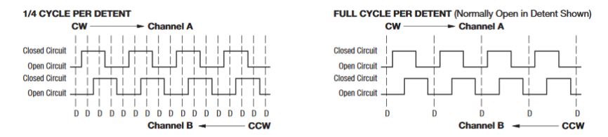
That is the full cycle/detent type (see the picture above, “open in steady state”).
If you connect the 2 pullup resistors (ie 10k) it will read “1” on both in steady state (at the detent, but there are encoders without the detents, they rotate “smoothly”). While increment (CW/CCW) it will pass via “O” and return to “1” in steady state.
The 1/4 type will stay in “1” or “0” at a detent based on the actual position.
Thanks
I’m using 10k and 220nF (could probably use 100nF), with resistors both on the charge and discharge side of the encoder.
Seems to work very reliably just with a single ISR and reading the other output.
I briefly looked it doing it without hardware debounceing, but found it was quicker for me to solder the hardware than write and debug the code
However, be warned that the typical 1r+1c debouncers can trigger reset when coupled with a good switch / encoder. If that happens, put a small serial resistor there to delimit the discharging current.
for software debouncing, the Kuhn debouncer is very good for its simplicity: https://dannyelectronics.wordpress.com/ … debouncer/
as to 1/4 increments vs. 1/1 increments, one of the code pieces linked earlier has such features. But fredfox’s modification is very good as well.
There is a good discussion of debouncing on Hackaday (including the Kuhn method) at https://hackaday.com/2015/12/09/embed-w … ns-part-i/ and https://hackaday.com/2015/12/10/embed-w … s-part-ii/.
i use the “test_for_press_only” listing at the end of part II to read the momentary push button switch on the encoder and small tactile switches.
https://www.bourns.com/products/encoder … roduct/ECW
they cost me $5 each around y2k. Got them with a detent and without, 1cycle and 1/4, etc. Messed with DDS vfos at that time so I did the investment ![]() (btw I saw these in a TEK dso oscope teardown, so may be they will last long..).
(btw I saw these in a TEK dso oscope teardown, so may be they will last long..).
What is an another feature worth of implementing with the ultimate rotary encoder library is the “acceleration” – when you turn the knob faster than you usually do, the increments start to grow exponentially (ie. 2, 4, 8, 16.. based on the angular speed and/or the duration of the fast “kick”).
Thus with a slow knob rotation you incr/decr by 1, with a faster turn you can do “thousands”. I have that in my old vfos, but it is an ancient asm pic16 code not worth of messing with. It works fine, I can dial in a xMHz change with a few fast knob kicks with 1kHz “slow” stepping or dozens of kHz with 1Hz stepping..
PS: “accelerated input” could be done for example by measuring the “elapsed millis while the encoder’s A and B inputs incr/decrement” and each “Xnumber_of_elapsed_millis” will double the incr/decr step, till the millis2millis changes at A and B end.
(Its not my radio its someone else’s so I won’t even know if it works until I send it to them to test – but it works on my testbed)
