https://github.com/rogerclarkmelbourne/ … ncoder.ino
With my scope I determined that Physical Pin 14 and 15 were the simulator outputs.
I have connected Physical Pin14 to 12, 15 to 13.
 *TIMER2 inputs -> Digital Pins used to simulate.

* D2 -> D4

* D3 -> D5
Those D2, D4 names are from the maple. Pin numbers in the bluepill and the maple/maple mini do not match. Not sure what you are referring to with Phisical Pin 14 and 15, since I believe no version of the bluepill uses only numbers for the pins.
If you are using the DIP package pin numbers, that’s confusing, would be better to use PA0, PA1 etc for the rest of us to understand what you are connecting where.
As for the encoder timer function, it needs to use inputs (channels) 1 and 2 from the same timer to work. So the input pins need to be Ch1 and Ch2 of the same timer device.
PA_10 -> PB_5
PB_3 -> PB_4
as you can see here

I looked at the Maple pinout but could not correlate the pin D2-D5 so I ran the prog, assuming the pin allocation would sort itself out. I then looked for the simulator output which appeared on Physical Pin (those in light Turquoise on diagram) 14 and 15. I then remmed out the timer setup part of the programme and wagled what would be input pins D2 D3 up and down and using scope I found they were physical pins 12 and 13.
So I connected Physical Pin14 to 12, 15 to 13.
I just tried using PA10 instead of D2 as input in the programme.
PB3 instead of D3 as input
PB5 instead of D4 as output
PB4 instead of D5 as output
I got simulator output on PB5 but not on PB4
I connected PB5 to PA10 then PB3 but got:
1016 counts
direction 0
Full Revs: 4294967295
1016 counts
direction 0
Full Revs: 4294967295
1016 counts
direction 0
Full Revs: 4294967295
I am a bit confused but will investigate the pins later in more detail.
Jim
https://github.com/rogerclarkmelbourne/ … rd/board.h
Since none of them is assigned a value, the compiler will start from 0 for PA0.
To avoid confusion, always use PA0, PA1 etc in your sketches, since 0 in a maple mini corresponds to a different pin than a bluepill, and that may correspond to something else in another board.
About your pin selection, both inputs need to be Ch1 and Ch2 of the same timer.
PA10 and PB3 are different timers, and on top PA10 is Channel 3 of that particular timer.
Correct me if I’m wrong, but according to the reference manual, you need to use inputs 1 and 2.
In the diagram, PA8 and PA9 are Ch1 and 2 of the same timer, try those 2.
I also got timer 1 3 and 4 working using:
HardwareTimer timer(1); PA8-9
HardwareTimer timer(3); PA6-7
HardwareTimer timer(4); PB6-7
And learnt a lot in the process.
Thanks
Jim
I required a rotary encoder to make a draw wire transducer with a 1 mm resolution. I have a 20 mm dia pulley attached to my rotary encoder, so PI*D = 62.8 mm. So I purchased a Bourns EM14 rotary encoder with 64 PPR which makes each pulse approx 1 mm (corrected by a scale factor).
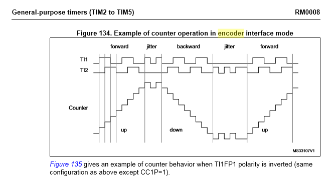
Referring to the ST “RM0008 Reference manual” ( Page391) in quadrature encoder mode the counter counts up on each transition of the two inputs. That means that the counter actually counts 4 * 64 = 128 PPR, which would have been good in hindsight as I could have used a cheaper 16 PPR encoder.
- QuadCounter2.png (22.15 KiB) Viewed 1258 times
The reason to substract 1 is because the prescaler settings start with 0:
0 -> divide by 1
1 -> divide by 2
2 -> divide by 3
3 -> divide by 4
It’s the way the prescaler register works, documented in the reference manual if you want to find more.
If you use timer.setPrescaleFactor(5) your scale will be off.
[victor_pv – Wed Nov 29, 2017 4:09 pm] –
About your pin selection, both inputs need to be Ch1 and Ch2 of the same timer.
PA10 and PB3 are different timers, and on top PA10 is Channel 3 of that particular timer.
Correct me if I’m wrong, but according to the reference manual, you need to use inputs 1 and 2.In the diagram, PA8 and PA9 are Ch1 and 2 of the same timer, try those 2.
I’m a little confused. What do you mean with “both inputs need to be Ch1 and Ch2 of the same time?
My timer.getCount() just works fine, but func does nothing…
I have a real encoder wired up, so i don’t need that emulation things.
this is my code:
#define PPR 1024
HardwareTimer timer(3); //initialize a timer
long ints = 0;
void func(){
if (timer.getDirection()){
ints--;
} else{
ints++;
}
}
void setup() {
//define the Timer channels as inputs.
pinMode(PA6, INPUT_PULLUP); //channel A
pinMode(PA7, INPUT_PULLUP); //channel B
Serial.begin(115200);
Serial.println("encoderTest");
//configure timer as encoder
timer.setMode(1, TIMER_ENCODER); //set mode, the channel is not used when in this mode.
timer.pause(); //stop...
timer.setPrescaleFactor(1); //normal for encoder to have the lowest or no prescaler.
timer.setOverflow(PPR); //use this to match the number of pulse per revolution of the encoder. Most industrial use 1024 single channel steps.
timer.setCount(0); //reset the counter.
timer.setEdgeCounting(TIMER_SMCR_SMS_ENCODER3); //or TIMER_SMCR_SMS_ENCODER1 or TIMER_SMCR_SMS_ENCODER2. This uses both channels to count and ascertain direction.
timer.attachInterrupt(1, func); //channel doesn't mean much here either.
timer.resume(); //start the encoder...
}
//Support variables.
unsigned long interval=0; //variable for status updates...
char received = 0;
void loop() {
//encoder code
if (millis() - interval >= 100) {
Serial.print(timer.getCount());
Serial.print("\t");
Serial.print(timer.getDirection());
Serial.print("\t");
Serial.println(ints);
interval = millis(); //update interval for user.
}
}
Just a note, you have a full revolution set to 1024. From the output you show, you haven’t reached that. I haven’t personally used the timer as encode, but I believe that func() will be called when you complete a revolution. May be wrong on that though, I haven’t looked at how the timers work as encoders.

