#include <STM32ADC.h>

STM32ADC adc(ADC1);
uint8 tempSensor = 16;
void setup() {

Serial.begin(115200);

adc.calibrate();

adc.setSampleRate(ADC_SMPR_13_5);
// enabling either of the

// following two lines crash the system (PC13 is flashing):
// adc.setChannels(&tempSensor, 1);

// adc.enableInternalReading();

}
void loop() {

while (Serial.available() == 0);

Serial.read();

adc.startConversion();

float cpu_temp = adc.readTemp();

Serial.print("temp: ");

Serial.println(cpu_temp);

}
So, mine or Pito’s, either should work.
Ray
This is the Google search that found Pito’s code:
internal temperature sensor site:stm32duino.com
[electrobling – Tue Feb 27, 2018 5:39 am] –
The math in the library is way, way grossly wrong but I adapted it. I will post it soon.
Please do so.
#include <libmaple/adc.h>
const float AverageSlope = 0.0043; // V/oC, range specified .004 to .0046

const float V25 = 1.43; //Nominal volts, range specified  1.34 - 1.52

const uint16 voltsAt25C = round((V25 / 3.3) * 4096.0); // nominal ADC value at 25C
void setup() {

Serial.begin(115200);

setup_temperature_sensor();

}
void loop() {

//pause for a key input

while (Serial.available() == 0);

Serial.read();
uint16 reading = adc_read(ADC1, 16);
// show the raw ADC offset

int differential = voltsAt25C - reading;

Serial.print("raw ADC offset: ");

Serial.println(differential);
// convert ADC reading to Volts

float voltage = 3.3 * reading / 4096;

Serial.print("computed ADC volts: ");

Serial.println(voltage);
// show floating point computation value

float cpu_temp = (float)((V25 - voltage) / AverageSlope) + 25.0;

Serial.print("float calculated temp: ");

Serial.println(cpu_temp);
// compute temperature scaled by 100 as:

//  long scaledTemp = 33L * differential * 100000L / 4096 / 43 + 2500;
// expression numerator and denominator factored by 32 to avoid

// possible integer overflow:

//

long scaledTemp = 33L * 3125 * differential / (128 * 43) + 2500;
Serial.print("scaled integer temp: ");

Serial.println(scaledTemp);
Serial.print("scaled integer temp as float: ");

float makeFloat = (float)scaledTemp / 100;

Serial.println(makeFloat);

Serial.println();

}
void setup_temperature_sensor() {

adc_reg_map *regs = ADC1->regs;
// 3. Set the TSVREFE bit in the ADC control register 2 (ADC_CR2) to wake up the

//    temperature sensor from power down mode.  Do this first 'cause according to

//    the Datasheet section 5.3.21 it takes from 4 to 10 uS to power up the sensor.
regs->CR2 |= ADC_CR2_TSVREFE;
// 2. Select a sample time of 17.1 μs

// set channel 16 sample time to 239.5 cycles

// 239.5 cycles of the ADC clock (72MHz/6=12MHz) is over 17.1us (about 20us), but no smaller

// sample time exceeds 17.1us.
regs->SMPR1 = (0b111 << (3 * 6));   // set channel 16, the temp. sensor

}
[electrobling – Tue Feb 27, 2018 5:57 pm] –
…
Today could be the first time that a chunk of frozen meat was used as a CPU cooler!
I know you are 2nd in line behind me and we are likely not near the front of the line ![]()
#include <STM32ADC.h>

STM32ADC adc(ADC1);
void setup() {

Serial.begin(115200);

adc.calibrate();

adc.enableInternalReading();

adc.setSampleRate(ADC_SMPR_239_5);

}
void loop() {

//pause for a key input

while (Serial.available() == 0);

Serial.read();
float CPUtemp = adc.readTemp();

Serial.print("CPU internal temp : ");

Serial.print(CPUtemp);

Serial.println(" C");

}
Do you get some warning messages during build?
Turn verbose on.
C:\Users\Luser\AppData\Local\Temp\arduino_build_730770\libraries\STM32ADC\STM32ADC.cpp.o: In function `STM32ADC::enableInternalReading()':
C:\Users\Luser\Documents\Arduino\hardware\Arduino_STM32\STM32F1\libraries\STM32ADC\src/STM32ADC.cpp:47: warning: undefined reference to `enable_internal_reading(adc_dev*)'
uint16_t STM32ADC::readTempi() {

uint16_t result = adc_read(_dev, 16);

return result;

}https://en.wikipedia.org/wiki/Silicon_b … ure_sensor
However, using the uC as an ambient temperature sensor implies that the uC will remain at ambient temperature: requiring the sink/source output CMOS drivers to be minimally loaded and the uC to have sufficient air flow to dissipate any self-heating.
IMHO, it is rather absurd unless the intent is to keep watch on the uC temperature proper, as in over-clocking or heavy current loading of the output. It is an interesting lab experiment, but minimally useful in any real-world device. You will get better results from a 10-cent thermistor and use of the Steinhart-Hart approximation. If 5% or less results are needed for a limited range, a thermocouple driven 8-bit A/D with look-up table will suffice: Old PICAXE example.
Ray
Looking forward to using the library upgrade you’re working on.
The technique is so simple that a library is simply an overkill in my opinion. Too many STM32DUINO users are hooked completely on libraries. Break your chains and write your own function or write your own library. Libraries are a two-edged sword for Arduino … yes, the Arduino infrastructure is quickly made available but the experimenter/programmer is locked-into a paradigm created by someone else. Far too many end-users simply cannot do anything if there is not a library to make it happen! This is sadness.
Challenge yourself to minimize the use of libraries for your own projects. Rework a common library that you use often, maybe a display library or a GPS library. If you are an experimenter, never write the same code the same way … there are a zillion ways to get from point A to point B … discover something new.
Ray
I tested it only for fun, calibration mean only to have numbers more similar to real ones. But I found that internal was better than a DHT11 (okay, it’s easy!)
Here is an example, six days (I have 14 months of data)
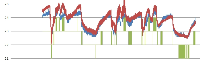
- SensorsTest.jpg (51.83 KiB) Viewed 684 times
[zoomx – Tue Mar 06, 2018 9:31 am] –
…
I tested it only for fun, …
In this test the MCU did nothing, only a measure every 20 seconds using delay and it was inside my office.
…
zoomx,
I agree it is fun and the graph is rather interesting. You and I however have been schooled into knowing that the use of the internal band-gap diode is not generally for ambient temperature, some newbies may not know that. My remarks about the sensor use were more academic such that the reader did not go down a path of thinking that would lead to the belief that its use would be a good idea. ![]()
Ray
I had to remove the link to the image, because that site serves porn images if you click on the link
Please just upload the image to the forum
Done! Thanks Roger and excuse my mistake using the first image hosting service that I found.
No worries.
Looks better to have the full size image in the forum anyway…
BTW. Did you put the STM32 into low power / sleep mode in between taking readings ?
I remember doing some tests when I was overclocking the STM32 to 128Mhz and it started to get warmer by a few degrees.
The heating was not a problem for its operation, as I think it was less than 5 deg increase in temperature at 128Mhz (probably 2 or 3 deg)
But, perhaps this is not a problem when running at 72Mhz
I am planning a test with many sensors using Arduino and an STM32 but I have to put it outside since in office temperature variation is not good for the experiment (but good for me!).
I am planning a measure also against MCU load and maybe I will use a borrowed FLIR thermal camera.
[zoomx – Thu Mar 08, 2018 9:15 am] –
…
and maybe I will use a borrowed FLIR thermal camera.
Yea! Pictures … so cool …colloquially speaking ![]()
![[Pending Enhancement] RTC values resetting](https://sparklogic.ru/wp-content/uploads/2019/11/nucleo-l476rg-zestaw-startowy-z-mikrokontrolerem-z-rodziny-stm32-stm32l476-90x90.jpg)