Still requesting the schematics diagram from the seller ..
I would like to use this method as mentioned in the wiki https://github.com/rogerclarkmelbourne/ … /Uploading
1. Connect USB Serial to PA9,PA10 ( Rx, Tx on 3.3V using FTDI )
2. Boot setting :BOOT0 – 1 , BOOT – 0
3. Setup Arduino IDE 1.6.3 with arm compilers
4. Board is Generic STM32F103Z
5. Variant STM32F103ZE
6. Upload Method – Serial ( i assume this is direct without any bootloader )
I just wanna send the blink example to this board … still figuring out where are the on-board LED are connected to..
I saw there is a UART2 at lower right of the picture with 3.3V, Gnd, Rx2 , Tx2 ( is this PA9,PA10 ?? )
Any other precautions besides Rx,Tx must be 3.3V ??
Will I in anyway brick the board ??
to me looks it looks ok, crossing tx/tx shouldn’t/doesn’t, my favourite:-)
i’m staying well away from the the db9’s on my assorted boards, not sure if i still have a vt100 somewhere
pick up a couple of st-link’s ~£2 ukp – see relevant section for a pic, will enable recovery from brick apparently.
for second one – play with blackmagic maybe?
[/edit] [edit2] found it i think, did you buy the display or included? what size please? any ident/model info on its back?
taobao buying in english’ish
http://mytaofocus.com/item.php?id=44445803337
https://detail.tmall.com/item.htm?id=44 … oSite=main
[/edit2]
stephen
M3S dev board :-
http://world.tmall.com/item/44445803337 … 0.0.fcrEFL RMB79
3.2″ Display with touchscreen :-
http://world.tmall.com/item/43423175309 … 3423175309 RMB59
Both items was together and comes with a plastic box
I found a chinese forum at http://www.doflye.net/ but they are all in chinese, getting my friends to find me the d/l area for this dev board ..
Will I in anyway brick the board ??
i make that price a tad under 15ukp, plus agent fee? and postage?
would be interested in the circuit as well
my 3.2 lcd/touch + rb board has a 32pin connector, 16bit data and 8080 control, spi for disp controller?? touch and sd socket
immense variation in lcd connections
stephen
If your PC has serial port i.e its old enough to have one… and you have a cable, you could try connecting to the PC, and setting Boot0 HIGH then download STM’s on STM Flash Loader Demonstrator (not sure why they call it a demonstrator but I’m pretty sure they call it that)
Then see if STMs prog will communicate with the board.
If it can, then you can either upload via serial from the Arduino IDE or have a go at loading the bootloader (see if you can find an existing bootloader bin that is precompiled with the LED on he same pin that you have a LED – but any generic bootloader bin would probably with most of the versions the only difference is which LED they flash)
Of course the bootloader will only work if the USB D+ line is pulled up by a resistor to 3.3V (usually the resistor is somewhere between 1k and 4.7k )
But also… I totally agree with Andy. But a STLink (clone) from eBay or Aliexpress etc, as they are a virtually foolproof to upload, as they can even attach to the MCU when its in reset (but they can’t upload under reset)
And the STLink should (in the fullness of time ) allow in circuit debugging
I’ll definitely get a ST-Link (or clones) in my next order…
For the pullup to D+, I did a trace and snap a pic of the resistors connected to the MicroUSB ..
It was connected to resistor 152 code, it is a 1.5K resistors…
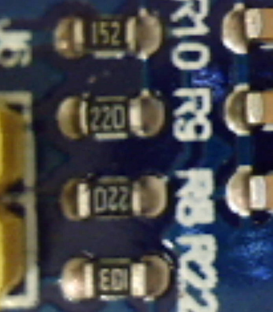 M3S USB by stanley_seow, on Flickr
If that is the case, then you can use the rom bootloader by setting Boot0 and Boot1 to the correct level (I don’t remember the right levels off the top of my head, please check the datasheet).
Once the MCU is in serial mode, you can use the st “bootloader demostrator” tool to upload a sketch via serial, or more practical to upload the stm32duino bootloader.
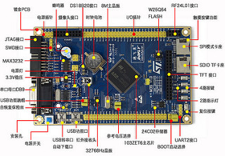
Please check and confirm if the schematic shows one of those usb to rs232 converters connected to usart1 and 1 of the usb ports, and if so we can give you more details on how to use it.
EDIT:
This is from the board link:
7, USB-TTL serial converter circuit, USB interface, serial communication
So yes, it has the usb to rs232 converter. You dont need to use a usb to serial adapter, but just find out which of those usb ports in the board is the one going to the onboard converter, then install the driver for that chip, whatever it is (pl2303 or whatever else), then use the method you described in the first post to upload to it.
I will share them here for future references…
https://www.dropbox.com/s/uwfjx7iro06co … 0.pdf?dl=0
Other Files related to this LY-M3S dev board
http://pan.baidu.com/s/1gdF84dP
Since I’m already using Chinese Nano, they uses the same CHG340G USB-Serial IC ..
A BIG THANK YOU everyone for the replies and all the people that made this STM32duino possible… Open Source community rocks!!!
Also tried simple stuff like reading the buttons and making some noises on the on-board buzzer ..
![]()
![]()
![]()
![]()
More to come ….
I’m glad it works.
Uploading using the bootloader is usually easier than using USB Serial (even if the usb to serial is on the board), because you need to manually press the reset button first etc
So I’d recommend you try flashing the bootloader.
There is a precompiled binary which uses a LED on PE5 that you could try
see
https://github.com/rogerclarkmelbourne/ … 1/binaries
specifically
https://github.com/rogerclarkmelbourne/ … 20_pe5.bin
This version has the “button” defined as PD1 pressed = high , but it should work, and if not, let me know and I can compile a version using PB5 or PE5 for the LED with the button on a different pin, or no button at all
I managed to upload the flash using STM32duino bootloader
Opening USB Device 0x1eaf:0x0003...

Found Runtime: [0x1eaf:0x0003] devnum=1, cfg=0, intf=0, alt=2, name="STM32duino bootloader v1.0  Upload to Flash 0x8002000"

Setting Configuration 1...

Claiming USB DFU Interface...

Setting Alternate Setting ...

Determining device status: state = dfuIDLE, status = 0

dfuIDLE, continuing

Transfer Size = 0x0800

bytes_per_hash=291

Starting download: [##################################################] finished!

state(8) = dfuMANIFEST-WAIT-RESET, status(0) = No error condition is present

Done!

Resetting USB to switch back to runtime mode
What happens if you press the reset button.
PS are you on PC or Mac or Linux?
Win 7, 32-bit, Arduino 1.6.3
Looks like the new hex was flash into the STM32 but not executed after a reset I guess..
The sketch flashed in was just a blink example on the PB5 LED
I tried a few times just to be sure …
I also notice that after I flash it for the first time successfully after a unplug-plug USB, the second or third time, it could not find the DFU device any more WITHOUT a plug-unplug USB port no matter how many times I press the reset button..
Does this have to do with the “Windows OS got confused of the USB port after a reset” issue ??
Reset via USB Serial Failed! Did you select the right serial port?

Assuming the board is in perpetual bootloader mode and continuing to attempt dfu programming...
maple_loader v0.1
Resetting to bootloader via DTR pulse
Searching for DFU device [1EAF:0003]...
dfu-util - (C) 2007-2008 by OpenMoko Inc.
This program is Free Software and has ABSOLUTELY NO WARRANTY
Couldn't find the DFU device: [1EAF:0003]
There is a lot of confusion about how the DFU and serial works
DFU is in the bootloader, the Serial device is uploaded a part of the sketch if you select to upload via the bootloader
The bootloader resets the USB bus by driving USB D+ (DP) low by changing the pinmode of D+ to GPIO, and then the pullup resistor is supposed to pull the USB D+ line back to 3.3V after the bootloader has changed the pinmode back to USB controlling that pin
If you press the reset button and you see the board re-enumerate on USB in the Windows device manager, it means that the bootloader is managing to reset the USB bus (USB D+).
When the sketch runs, it also does the same trick of driving USB D+ low, which causes the USB to re-enumerate and it should then appear as Maple Serial
But it sounds like the sketch is not resetting the USB – which is odd if the bootloader had managed to do it.
Are you going through any USB hubs ??
If you press the reset button and you see the board re-enumerate on USB in the Windows device manager, it means that the bootloader is managing to reset the USB bus (USB D+).
When the sketch runs, it also does the same trick of driving USB D+ low, which causes the USB to re-enumerate and it should then appear as Maple Serial
But it sounds like the sketch is not resetting the USB – which is odd if the bootloader had managed to do it.
When you mentioned “USB hub”, it gives me a hint to tried both method, via usb hub and direct to the USB port..
With usb hub (in the Dell monitor), pressing the reset button will NOT re-enumerate the USB
With direct USB port, pressing the reset button will re-enumerate the USB
With a direct USB port, after the flashing hex, it DOES reset the board, re-enumerate the USB and the Maple DFU device was gone ( but the Serial device “never” appear )
Is the Serial USB codes compiled into the hex automatically ??
But this time, I did get the last line error :-
“error resetting after download: usb_reset: could not reset device, win error: The system cannot find the file specified.”
Is Arduino looking for the Serial port ??
By just pressing the reset button, the Maple DFU re-appear (back to bootloader mode, i guess ? )
bytes_per_hash=294

Starting download: [##################################################] finished!

state(8) = dfuMANIFEST-WAIT-RESET, status(0) = No error condition is present

Done!

Resetting USB to switch back to runtime mode

error resetting after download: usb_reset: could not reset device, win error: The system cannot find the file specified.
Some machines seem to give this error. We are not sure quite why it is displayed, but it is not important.
Please ignore this message.
I presume you have loaded the Windows drivers? You say that you can see the DFU device, so I think you must have loaded the drivers, otherwise you would not see the DFU device.
Occasionally there are machines that are too slow to look at the USB after enumerating, but this is rare.
How old / new is you PC ?
I usually use this USBDeview to troubleshoot or view USB devices http://www.nirsoft.net/utils/usb_devices_view.html
The BOOT0 and BOOT1 should be at LOW, right ??
Well Boot1 only matters if Boot0 is High, it can be any state if Boot0 is low
3.1GHz machine is plenty fast enough. I run on 2Ghz machines with no problem at all
Its really difficult to know why this does not work for you, because there are multiple unknows.
Which generic bootloader bin file did you use? It could be your board is pulling the “button” pin for that specific version of the bootloader to HIGH
When you plug in the board, does the LED flash a few times fast then keep flashing about 2 x per second?
EDIT.
I just tried holding the button down on my Maple Mini and after it uploads I don’t get the Maple Serial device
So I strongly suspect that your board is pulling the pin that is assigned in the .bin file you have used, to High and this is preventing it working
Does your board have a “user” button, and if so, what pin is it on ??
I will need to make a new bootloader variant that has the LED for your board and either the button to match your button, or specifically to not have any button input pin.
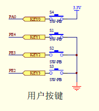
From the circuit, the reset is pull-up
Pressing button will Gnd it
4 extra user buttons are: –
PA0 , PRESS to pull up
PE4, PE3, PE2, PRESS to pull down to Gnd
PA0 ?? or one of the others ?
You decide the button.
Choose button that are common to other boards
Thanks
I’ll make a new bootloader version that uses the LED on PE5 and the button on PA0 (active high button)
I’ve done a new bootloader variant, which is the same as the PE5 version except it expects the button to be on PA0 which goes High when you press the button.
Note if PA0 is not pulled low, there will be problems of the pin floating, but I presume if you board has a user button on PA0 which pulls that pin high, they would have included a resistor to normally pull it low (when the button is not pressed)
Thanks for compiling the new bootloader .. after the bootloader installed , I observe the following :-
The Arduino IDE is able to reset the STM32 into DFU mode for firmware upload – OK
After the Upload, it was able to reset the STM32 and run the new uploaded sketch – OK ( previous, this was not possible )
BUT the Maple Serial (COM61) does not show up … after the soft reset..
Only when I press the RESET button, the Maple Serial (COM61) appear …
I’m not sure what does the switch PA0 does but the old issue of not getting the new uploaded flash to run was solved.
I use Serial.print() to print out S1, S2, S3, S4 when those buttons was pressed .. only S1, S2, S3 was detected..
It is normal for S4 (PA0) not to be detected since it was used by the bootloader ??
 STM32 M3S buttons by stanley_seow, on Flickr
I’m glad things are a little better.
This is the first occurrence on PC of this problem, that I know about.
I’d recommend that you buy a Maple min for around $5 on ebay or Aliexpress etc, and confirm that it works ok (to verify that your PC is not the problem)
<…>
BUT the Maple Serial (COM61) does not show up … after the soft reset..
This is the first occurrence on PC of this problem, that I know about.
I’d recommend that you buy a Maple min for around $5 on ebay or Aliexpress etc, and confirm that it works ok (to verify that your PC is not the problem)
You need to use generic or the usb enumeration will not work right.
![[SOLVED] Discovery STM32F100RB — Trouble with timers and library structure](https://sparklogic.ru/wp-content/uploads/2019/11/st-stm32vl-discovery-90x90.jpg)
