acquired PPS pulse... starting calibration
0: diff = 0 ................................

32: diff = 1 ................................

64: diff = 2 ................................

96: diff = 3 ................................

128: diff = 5 ................................

160: diff = 6 ................................

192: diff = 7 ................................

224: diff = 8 ................................
*** Calibration completed ***

Calibration cycles:8

Calibration time:256 seconds

measured divider difference:9

calculated correction factor:1.12

rounded correction factor:1.00

calibration value result:65

Calibration values applied, testing now...
0: diff = 0 ................................

32: diff = 1 ................................

64: diff = 1 ................................

96: diff = 1 ................................

128: diff = 1 ................................

160: diff = 1 ................................

192: diff = 1 ................................

224: diff = 1 ................................

256: diff = 1 ................................

288: diff = 1 ................................

320: diff = 2 ................................

352: diff = 2 ................................

384: diff = 2 ................................

416: diff = 2 ................................

448: diff = 2 ................................

480: diff = 2 ................................
*** Test Cycle completed ***

Test time:512 seconds

measured divider difference:2

calibrated accuracy:0.131 PPM

Calibration test complete...

To calibrate again press a key to continue:
But since the Blue Pill has a 32K clock crystal, why not use that? http://stm32duino.com/viewtopic.php?t=1335
Ray
I named the presentation slides file HSE instead of LSE. Oops. Fixed that.
I’m thinking of something along the lines of a TCO style correction where you place the crystal in thermal contact with the processor, or even add a small resistor heater and an external ntc to keep the crystal within a narrow temperature range.
Simply assuming the crystal temperature will vary directly in line with cpu temperature is probably a good starting point for experiments of this sort.
I wonder what the theoretical accuracy limit is.
Crystal ovens depend on special crystals that have a nominal working temperature well above room temperature. The tempco is an inverse parabola, so you really want the crystal operating at the top of the curve where the delta is the smallest. That is why 32kHz crystals have the peak of the curve at 25C. I read somewhere that the really select watch crystals peak at body temperature, because a watch case approaches that when worn on the wrist. Not sure if that is true or urban legend.
In the slide show I posted, I cover temperature compensation. But calibration is a big issue. One problem is the variations in the actual response of a given crystal. To measure the actual response, I think, requires a 3 point measurement where the PPM difference is measured at 3 different temperatures. That is because you can’t tell where the actual peak is from only 2 measurements. I observed a lot of variation from board to board – up to 8PPM. Also the supply voltage matters. I noticed a huge difference with the Blue Pill LSE timing, depending on whether VBB was connected to 3.3V or not.
The system that I have aims at “low hanging fruit”. I de-populate the pins PC14 and PC15 because they are OSC32in and OSC32out. That reduces the capacitance and coupling to external hardware, without any significant mods to the board. I connect a BAT46 diode in series with VBB, and connect a coin cell to it.
My experience with calibrated, room temperature 32kHz oscillators is that they will maintain about 1-2 PPM over a long time. To improve on that, really becomes a game of diminishing returns (because of escalating cost and complexity). The thing that would not be overly complex to add to what I already have now, is temperature compensation. It could be done with the processor temp sensor, but I think that would work best if sleep modes are implemented so it’s not any warmer than it has to be.
In fact, the processor temperature is a “red flag” issue for calibration because, unless it is run in sleep modes, it significantly raises the temperature of the crystal and more so if it is in a small enclosure. So calibration has to be performed on a fully assembled, warmed up system.
Perhaps not.. but that does sound like a challenge that might be worth investigating.
The DS2321 states the following in the datasheet.
Accuracy ±2ppm from 0°C to +40°C

Accuracy ±3.5ppm from -40°C to +85°C
[Pito – Tue Feb 20, 2018 3:40 pm] –
You cannot beat the DS3231, no chance. No crystal heater needed, no calibration, around one uA current in average, few secs/y off, not loosing time when BPill is flashed..
Well, I’m a fan of the DS3231. But I am now enjoying the idea of a complete system on one board, not including peripherals like displays and such. An RTC that isn’t onboard is another module to contend with. I now have a working clock that consists of one Blue Pill and one TM1637 LED display. With only four wires between them. I like the simplicity. If I want to add an ESP8266 I could do it, but beyond three modules and it starts to become a mess. For the same reason, I am awaiting shipment of some STM32 boards that have onboard sockets for such things, even an OLED display. So I need a better reason to use it. Also the DS does not provide access to fractional time as the ST RTC does. I don’t need the silly broken down time byte units that have to be translated to proper epoch time which is what I use for everything. The DS does not provide RAM backup, the ST does have 20 bytes. Battery drain spec for the DS is 0.84uA typ, the ST is 1.4uA, only slightly more.
As wonderful as the DS3231 is, I have observed that simple circuits can challenge it in some situations. I had some fun 2 years ago, applying handmade foil sheet trimmer capacitors to dollar store clocks. The best of those can maintain time at room temperature to within about 15 seconds a year. Of course, if the temperature changed, those would be hosed. I’m an experimenter. If you hand me a toy, I want to play with it to the maximum extent that I can think up. It seems to me that the existing RTC circuit on the Blue Pill fits well into my tiered time source strategy, which integrates local and external time sources such as GPS or NTP, in fact simplifying it because no additional components are required, and I don’t have to depend on software to maintain fractional time. It’s a free toy too. Every Blue Pill I’ve see so far has the circuit. So making it work correctly is in my mind, not anything I have any doubt about, especially since it’s already done.
Also, I haven’t experienced any loss of time while flashing. I could be wrong, but I think the backup domain is not reset unless both VCC and VB are removed.
You have triggered an idea for another experiment – The DS3231 has a 32kHz output that could be connected to the LSE as an external clock input. That might be interesting to play with. That output is on by default at power up, so no I2C connections would be necessary.
Edit – regards exceeding the DS3231 performance – that would be nearly impossible. There is short term and long term stability to think about. But in the end, the DS is just a crystal oscillator with some hardware around to condition it. I think that if you could calibrate and compensate for temperature, you could equal or even barely exceed the DS performance. But as I pointed out earlier, active compensation relies on power. At a minimum, you would have to sleep the processor and wake up periodically to emulate the roughly once a minute temperature updates that the DS performs. So you would have to find a way to run the processor on battery power unless you don’t expect long power interruptions. In fact, for a table or wall clock, that is usually the case.
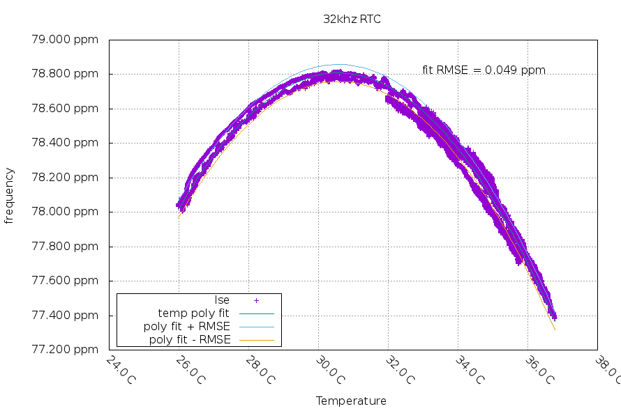
The temperature was measured by the built-in CPU sensor, and does a decent job (probably because they are close to each other and connected via metal tracks). There is about 0.049 ppm frequency uncertainty at any given temperature that I measured. A quadratic equation fit pretty well, which matches the datasheet for my crystal.
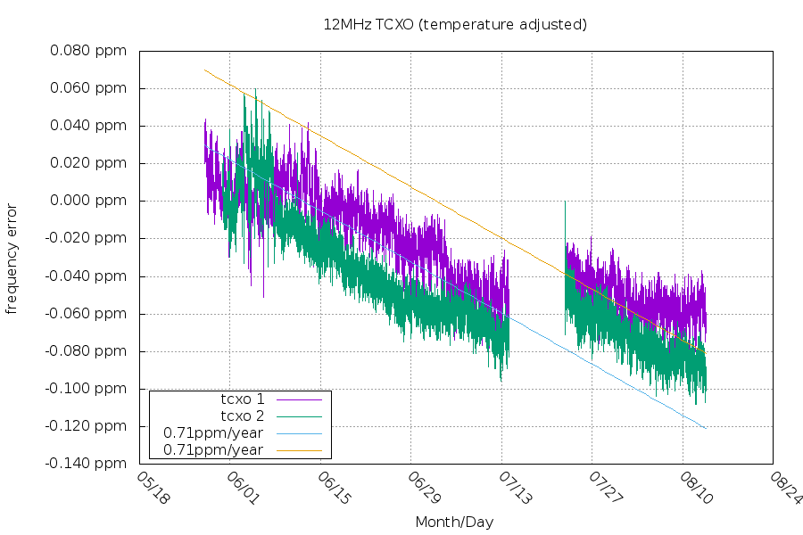
The second factor is aging. This graph is for a TCXO instead of the 32KHz crystal. Its datasheet spec is 1ppm/year for the first year.
And lastly, you mention the frequency changes with voltage. I don’t have a nice graph for this, but it is true ![]()
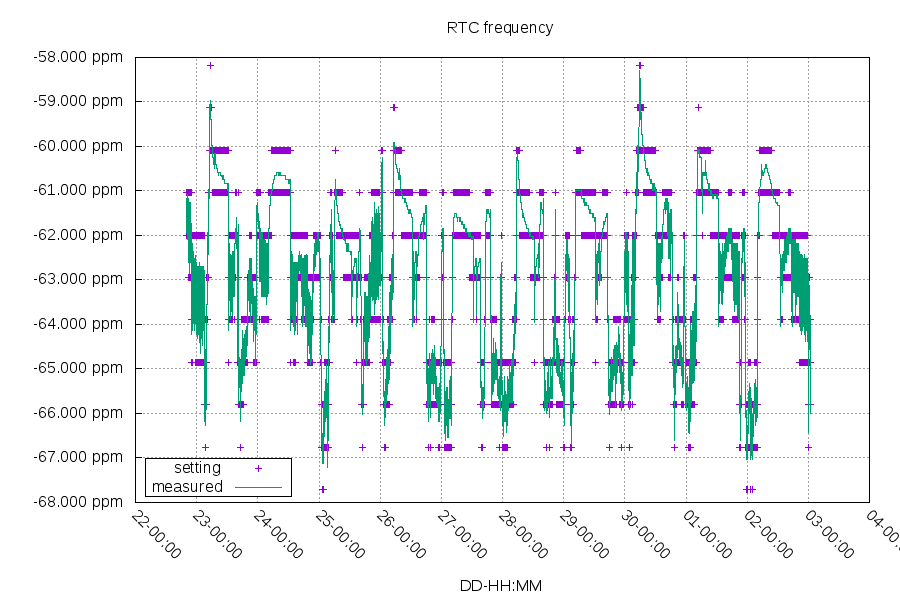
I’m using dithering to set the RTC frequency, so I can get much better than 1ppm while the CPU and TCXO are running:
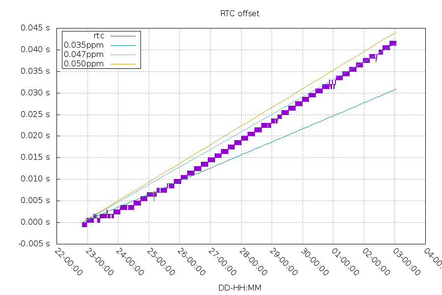
This is good for around 0.047ppm (~40ms in ~10 days), which is probably the limit of my TCXO:
The DS3231 has a large benefit in that it can continue to correct its local frequency on a coin cell battery. So you’d need to consider “on coin cell” vs “off coin cell” times. The more time spent on the coin cell, the better the DS3231 is going to do.
Additional information about the RTC measurement (“data on the RTC” section)
At least the dithering is working, here is the code:
// once per second ISR

// fractional dithering of the Calibration Register

void fractionalDither()

{

static int cycleCount = 0;

const int COMPENSATIONCYCLE = 32; // defined in clock calibration hardware

static int accumulator = FRACTIONALGRANULARITY / 2;
if (runISR and fractionalCalibrationConstant != 0)
{
cycleCount++;
if (cycleCount >= COMPENSATIONCYCLE)
{
cycleCount = 0;
accumulator -= fractionalCalibrationConstant;
if (accumulator < 0)
{
accumulator += FRACTIONALGRANULARITY;
ditherOn = true;
rt.setCalibrationRegister(truncatedCalibrationConstant + 64 + 1);
}
else
{
ditherOn = false;
rt.setCalibrationRegister(truncatedCalibrationConstant + 64);
}
}
}
}
how the ADC library function readTemp() is supposed to be used.Except the DS measures the internal crystal temperature at specific intervals (you can set the period) and it adjusts the internal tuning capacitors accordingly, it has got the aging register where you may adjust the (changing) offset as well. It has got a backuped sram as well (DSxx32).
The DS’es 2ppm is for 0-40degC, when using it at ambient temperature (say 23 +/- 3degC) you get a few secs/y (mine cheapo module did 4secs/6Months without messing with aging).
PS: the cheapo modules I got use the “N” version with -40°C to +85°C.
DS claims “Accuracy ±3.5ppm from -40°C to +85°C” – that is an unbelievable accuracy provided you have got an idea what -40°C to +85°C does mean.. ![]() (your coin battery stops working at -40 and may explode at 85)..
(your coin battery stops working at -40 and may explode at 85)..
Presumably since the resistive oven is only able to heat the crystal, but not cool it then if the ambient temperature exceeds +85°C, there is nothing the DS can to to maintain the regulation of the crystal.
Incidentally your battery also explodes if charged at 3V3…
It measures the temperature, and based on a calibration table it changes the capacitors values.
The DS chip itself is a pretty complex rig, maybe more complex than the 103C8 itself
Here are the DS silicon shots:
https://blog.heypete.com/2017/07/29/a-l … ime-clock/
From that blog:
– The reference signal is a 1pps signal from my Trimble Thunderbolt GPSDO, which has an accuracy of +/- 20ns or so. This is fed into my oscilloscope as the trigger signal.
– The 32.768 kHz signal from the DS3231 is connected to a Schmitt trigger to clean up the rising edge (the module I have has a 4.7 kOhm pull-up, so the rising edge is a bit slow), the output of which goes into one of the channels on the oscilloscope.
I set the oscilloscope to 1-2 microseconds per division, then watch the pulses drift left or right over time. I start a timer when one of the pulses reaches one of the marks on the graticule and time how long it takes for the pulses to drift such that a different pulse reaches the graticule. Usually, it takes a minute or two with the un-trimmed oscillator, which corresponds to 0.25-0.50 ppm.
My current understanding is if you put the DS into a box made of 1inch thick polystyrene foam, with stabilized and filtered 3V supply, and you will adjust the aging reg, you have to achieve <1sec/y.
https://github.com/rogerclarkmelbourne/ … 2/pull/467
Hope you can improve the situation.
[chinhduy – Sun Mar 25, 2018 3:26 pm] –
I fail to use the internal RTC of Blue Pill, 3 clone boards gave me 3 results. The first board was quite accurate but the 2 others were behind 2 hours/day. SO I turned back to DS3231 with its 24C32 EEPROM.Hope you can improve the situation.
What circuit are you using to provide a voltage at VBAT? I discovered that it is important to have a stable external voltage there. I’m now using a pair of Schottky diodes to supply it either from a battery, or VCC.
I already have a compensated clock running on my desk. I just haven’t tackled the problem of how to share the code. For example, the RTC library currently doesn’t provide access to the calibration constant register. I had to mod it to do that.
[hyperion – Fri Mar 23, 2018 3:16 am] –
create PR to calibrate RTC which enables tamper output on PC13 pin
https://github.com/rogerclarkmelbourne/ … 2/pull/467
There are actually three states you need to make the cal work
1) Calibrated operation disabled
2) Calibrated operation enabled
3) Perform calibration
I think you need to separate these better. The general differences would be:
1) load 7fff, cpu cal op disabled, cal constant is “don’t care”, tamper off
2) load 7ffd, cpu cal op enabled, cal constant is 64+/-n, tamper off
3) load 7fff, cpu cal op disabled, cal constant is “don’t care”, tamper on
Have you read the document I posted? The ST app note doesn’t dig nearly deeply as it could to the fundamental equations. I think there should be a lot more design work before a library change is warranted. I do think it would be a useful feature.
I would also like to know, how many people would be able to use the tamper output to perform an actual calibration? The straightforward answer is a highly accurate frequency meter, but that is an expensive piece of equipment that most hobbyist don’t own.
When I tossed the idea around in my head, I thought a useful library option would be to offer a choice of 1) or 2), with 2) loading the neutral cal value of 64. Also the addition of methods to read and write the cal register. Then the method of calibration 3) would be up to the user. That could be as simple as waiting a month to measure the error “by wristwatch” and looking up the value from the chart and loading it.
[hyperion – Fri Mar 23, 2018 3:16 am] –
create PR to calibrate RTC which enables tamper output on PC13 pin
https://github.com/rogerclarkmelbourne/ … 2/pull/467
Maybe I should try to fold this request into an new request for an upgrade to RTClock since I have already implemented everything else I mentioned in the previous post?
What circuit are you using to provide a voltage at VBAT? I discovered that it is important to have a stable external voltage there. I’m now using a pair of Schottky diodes to supply it either from a battery, or VCC.
I already have a compensated clock running on my desk. I just haven’t tackled the problem of how to share the code. For example, the RTC library currently doesn’t provide access to the calibration constant register. I had to mod it to do that.
I simply connected the CR2025 battery to the VBAT.
[chinhduy – Tue Apr 03, 2018 8:23 am] –
I simply connected the CR2025 battery to the VBAT.
Be aware that ST documents a small current surge to the battery on VBAT at power up time. Some batteries might not like that. The other disadvantage with that approach is that the battery will always be powering the backup domain. With the dual diodes, power comes from VCC when the device is on (which, for my application, is mostly all the time… not sure what your usage is). That means that the battery will not last as long. Also unlike VCC, the voltage on the battery will drop over time, which will affect timing.
And my locale board vendor said that it was normal, the RTC of stm32f103c8t6 was that unstable, he advised me to use the DS3231 module.
More likely the crystal or the associated capacitors are the reason for the poor clock performance.
The STM datasheet is very specific about what type of crystal to use and the type and values of the caps and the board layout, but bluepill vendors completely ignore all of this and use whatever was cheapest at the Shenzhen market that day, and as a result, things either work acceptably well, or not at all. All of the boards I have tried, worked fine, including one that I added a salvaged crystal from an old clock module. I didn’t expect it to work, but it too was fine.
If you get a board with a decent crystal and the correct caps, it works fine, but it is a bit of a lottery. The DS3231 is completely self contained, so it is difficult for the cheap board manufacturers to screw things up. Difficult, but not impossible, such are the joys of using low cost boards from no-name vendors. ![]()
If you have the time, you could try substituting the crystal on the “3hrs a day” board, and see if it improves.
Pray tell – what type of battery did you use?
[chinhduy – Fri Apr 06, 2018 8:53 am] –
My application is Real Time clock, the VCC is not always available. I used two new battery with 2 new Blue Pill to compare. After one day, the first one was late 2-3s compare to my laptop time and the other was late 3 hours.
And my locale board vendor said that it was normal, the RTC of stm32f103c8t6 was that unstable, he advised me to use the DS3231 module.
There have been a couple of other threads about RTC issues, and so far as I recall they all turned out to be crystal related, or poor soldering by the board producer, rather than a faulty STM32F103
For example here-> viewtopic.php?f=3&t=2421&p=32443&hilit= … bay#p32443
.. and here.. viewtopic.php?f=15&t=132 (although this thread does get a little long, I blame the OP ![]() )
)
Wong value, damaged or missing load capacitors, or load capacitors inappropriate for the crystal will have a marked effect on accuracy, or may stop the thing from oscillating completely. Likewise an cracked, or stressed crystal will have different characteristics from a good one. Damaging the crystal with poor handling during manufacture can cause it to end up with stress cracks due to aggressive bending of its pins or overheating it when soldering.
That should be, I didn’t think that STM would sell bad MCU. The Blue Bill board I got was cheap Chinese clones, poor quality was acceptable.
DS3231 is a good solution for RTC and external EEPROM. No need to emulate the eeprom anymore.

