As a new ham operator I’ve been thinking of a few projects involving radio, rf, and micros. One of the projects uses a QRP Pixie. The Pixie is a small transceiver that you can get as a kit for less than $4. It works on the 40M band, which is ~7.025-7.125Mhz. Of course for a $4 transceiver you can’t expect many features. The one limitation right off the bat is it comes with a 7.023 crystal, which you’re stuck with if you solder it in. The 7.023 is not a frequency a Tech can broadcast on here in the states. The other option is mount a 2-in screw terminal and then you can swap out crystals. But then you’re limited to a finite set of crystals and could add up in costs and a pain to change frequency.
Another alternative is to use DDS signal generator to feed the circuitry whatever frequency you wish, within the range of the transceiver circuitry. Basically leaving off the onboard oscillator components and feeding the DDS signal directly into the board. This of course gives complete control over the frequency range.
Here are several DDS signal generators I’m looking at:
1. AD9833 – 0-12.5 Mhz
2. AD9850 – 0-50 Mhz
3. AD9851 – 0-70 Mhz
4. Si5351 – 0-150 Mhz
5. Si5351A – 0-290 Mhz
About all of these have breakout boards or you can buy complete units with display, rotary encoders or buttons. There are usually plenty of examples and code out there for all of the devices. I personally have the AD9850, Si5351, and the AD9833 that I bought off E-Bay. the Ad9833 is on it’s way.
Right now I’ve been playing with the AD9850 making sure I can wire it up, get a signal output, and look at the signal. Seems to work great. Without a spectrum analyzer I can’t tell the harmonics. My next step is to build my 2nd QRP Pixie kit and leave off the oscillator components and feed it the DDS output of the AD9850 and see the results. This will be fine for testing my theory of using it on the QRP and listen to whatever frequency I want in the 40m band.
A few notes to mention that probably applies to all of these. I’ve seen some tests on the outputs of a couple of these and due to several reasons they have some bad harmonic output. Bad as in if you were using them in a transmitter you would seriously check the output to make sure you’re not splattering other frequencies. The best suggestion is to use low pass filter or filters in your designs to get the levels of harmonics down to a manageable level.
I work 5 days a week and weekends are somewhat limited too. So as I work on these projects I’ll be glad to give updates. I also have a project that’s been a priority that I need to get done first. Mainly I wanted to share ideas if anyone needed some sort of signal generator for whatever purpose you need them for whether a function generator or a VFO for your radio. But if you do need any information on any of these I keep links on stuff I run across for reference such as sample code, datasheets, special notes, applications, etc. feel free to private message me. I’d rather you have over abundance of information than not enough and struggle.
Michael
I had a play with the AD9850 a while ago, and even managed to use it as an FM transmitter on the 100MHz band by continuously sending changes to the frequency in response to the ADC input.
Of course, its not supposed to operate above 40mhz, and the output is very weak. But as you are not allowed to broadcast on 100MHz and I had to put the radio very close to pick anything up.
But it worked better than Id expected!
I think you have one of those Tv dongles, which can be used as a spectrum analyser, but you would need an up converter e.g the “ham it up”
Michael, let me know the status of your build and I’ll can provide more info if needed.
What UI for the PC side do you use??
Michael
- DS2_QuickPrint1-2.png (68.63 KiB) Viewed 3830 times
For $9.90 you may get 20-30 doublesided pcbs with your design at Seeed..
I built a few softrocks in past, also with Si570. Rx comparable with big rigs.
Btw, the latest softrock designs use opto-couplers between Si570 and the mcu in order to reduce noise.
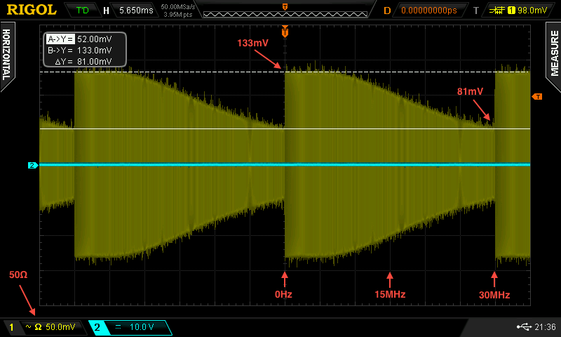
The response of the 9850/1 and others is given as (sin x)/x, imho (no low pass filter).
Then add the response of the low – pass filter.
Then add the response of the o’scope. In your case DS2072 I guess, so flat till 300 ![]()
As the first poster has indicated the 98xx output is not great (10bit DAC), so for high end I would use 9951 or 9912 (14bit).
The original VFOs output signals with those 7.023Mhz Pixies and RockMite clones are by factor worse than the 98xx ones, you can easily use 98xx.
The only question is the amplitude – the 985x output is something like 200mVpp, the NE612 needs a little bit more, the diode mixer even more, and the PA pre-amplifier much more. Thus you need to amplify.
Long time back (15y ??) I got these modules:
http://midnightdesignsolutions.com/dds60/
They got an onboard 50ohm capable amplifier handy (4Vpp at 50ohm).
I got the modules much cheaper as I had several 9851 in my junkbox already.
Sinusoidal wave in this case will have some drawbacks because we mix analog and digital signal and input stage of divider (usually 74AC74) will not interpret that signal perfectly well, some times will switch logic at one level, next time on other level (introduce additional jitter) and that produce some problems later in receiver.
This rule also apply for DBMs (diode mixer), with square wave we can switch internal diodes much faster than using sinusoidal wave.
On other side, sinusoidal wave is required for various RF measuring equipment likes VNAs or NAs where we must use it and as much as possible “pure” in wide range of frequency spectrum.

- AD9850-20MHz.png (39.38 KiB) Viewed 476 times

